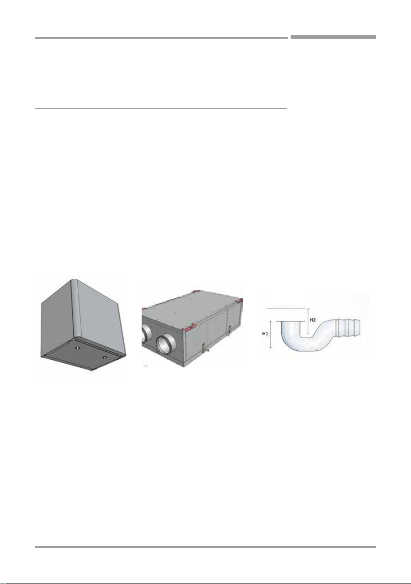
Aspira ASPIRCOMFORT H User manual

ASPIRCOMFORT H
INSTALLATION, USE AND MAINTENANCE MANUAL

2
ENGLISH
ASPIRCOMFORT H
1. GENERAL
1.1 INTRODUCTION
This manual was prepared with the aim of making the installation and management of your system as simple as
possible.
By reading and applying the suggestions of this manual, you can achieve the best performance of the purchased
product.
We would like to thank you for choosing to purchase one of our products.
Read this file carefully before performing any operation on the unit.
The unit must not be installed, nor must any operation be performed on it, without firstly reading and understanding
the entirety of this manual. In particular it is necessary to adopt all of the precautions listed in the manual.
The documentation provided with the unit must be delivered to the system manager for safe keeping (at least 10
years) for future assistance, maintenance and repairs.
Unit installation must take into account the strictly technical needs for good operation, as well as any local
legislation in force and specific requirements.
Make sure that when the unit is delivered there are no evident signs of damage caused by transport. If there is,
state this on the delivery note.
This manual reflects the state of the technical standards at the time of sale and cannot be considered inadequate
if updated at a later date based on new experiences. The Manufacturer reserves the right to update production and
the manuals without being required to update previous ones, except in exceptional cases.
Contact the Manufacturer’s Sales Office to receive further information or updates on/to the technical documentation
and for any suggestions for improvement to this manual. All suggestions shall be strictly vetted.
1.2 FUNDAMENTAL SAFETY RULES
Remember that the use of products that use electrical energy and water requires certain fundamental
safety rules to be followed:
• Unable and unassisted persons are forbidden from using the device
• It is forbidden to touch the device in bare feet and with wet or damp parts of the body
• Any cleaning activity is forbidden without firstly disconnecting the device from the electrical power mains by
placing the system’s main switch on ‘off’
• It is forbidden to modify the safety or regulation devices without the authorisation and indications of the
device manufacturer

3
ENGLISH
ASPIRCOMFORT H
• It is forbidden to pull, detach, twist the electrical cables coming out of the device, even if it is disconnected
from the electrical power mains.
• It is forbidden to insert objects and substances through the air intake and supply grids.
• It is forbidden to open the access doors to the inside of the device, without firstly placing the system’s main
switch on ‘off’.
• It is forbidden to release and leave packaging material within the reach of children as it is a potential source
of danger.
• Comply with the safety distances between the machine and other devices or structures to guarantee enough
access space to the unit for maintenance and assistance operations as stated herein.
• The unit’s Power supply must be provided with electrical cables duly sized for the power of the unit. The
voltage and frequency values must match those stated for the respective machines; all machines must be
earthed according to the regulations in force in the various countries.
1.3 SYMBOLS
The symbols used in the following file quickly provide information necessary for the correct use of the unit.
Safety symbols
ATTENTION
Authorised personnel only. This means that the stated operations are important to safe machine
operation
DANGER
Risk of electric shock. This means that failure to comply with the warnings poses the risk of
electric shock.
DANGER
This means that failure to comply with the warnings poses the risk of injury to the exposed
persons.
WARNING
This means that failure to comply with the warnings poses the risk of damage to the unit or
system.
DANGER
This means that there are moving parts and poses the risk of harm to exposed persons

4
ENGLISH
ASPIRCOMFORT H
1.4 WARNINGS
The unit must be installed by qualified and authorised personnel according to the rules in force in the
various countries.
If installation is not carried out, this could lead to a situation of danger
Avoid installing the unit in very damp rooms or where there are large sources of heat.
On the electric side, to prevent any risk of electrocution, it is essential to disconnect the main switch before
setting up the electrical connections and performing any maintenance operation.
If there are any water leaks from inside the unit, place the system’s main switch on ‘Off’, close the water
valves and contact the technical service
Always use a dedicated power supply circuit; never use a power supply shared with other devices.
Always install an earth leakage circuit-breaker; failure to install this device could cause electric shock.
For the connection, use a sufficiently long cable to cover the entire distance without any connection; do not
use extensions and do not apply other loads on the power supply, rather, always use a dedicated power
supply circuit.
When the electrical cables are connected, make sure that the cables are arranged so that they do not press
excessively on covers or electrical panels; any incomplete connection of the covers may cause overheating
of the terminals.
Make sure that the earthing connection is set up; do not earth the device on distribution pipes.
Momentary high intensity overcurrents may damage the unit
Installations made outside of the warnings set forth herein or use outside of the operating limits will
instantly void the warranty.
Make sure that commissioning is carried out by personnel authorised by the company (see commissioning
request form)

5
ENGLISH
ASPIRCOMFORT H
1.5 CONFORMITY
The CE marking (applied on each machine) certifies compliance with the following Community standards:
• Machinery Directive 2006/42/EC
• Low Voltage Directive 2014/35/EC
• Electromagnetic Compatibility Directive 2014/30/EC
• Ecodesign 2009/125/EC
1.6 RANGE
Code Maximum flow rate Installation
AP20056 Up to 350m3/h horizontal
1.7 IDENTIFICATION
-The unit can be identified by the rating plate attached to the front bottom panel.
-On the packaging there is another identification rating plate with the unit model and the shipping
references.
The rating plate on the packaging is not valid for tracking the product over the years after sale.
The removal, deterioration and illegibility of the rating plate attached to the unit makes machine identification and
ordering spare parts very difficult, and therefore all future maintenance.
1.1.8 CONSTRUCTION FEATURES
FRAME
Self-supporting sheet metal frame
Galvanised sheet metal panels, coated externally
with thermal and acoustic insulation, internal high thickness galvanised sheet metal infill.
HEAT EXCHANGER
Polypropylene high efficiency cross flow counter current exchanger.
Low freezing temperatures and operation down to -25°.
Very high exchange efficiency.

6
ENGLISH
ASPIRCOMFORT H
FANS
Brushless fans with electronic motor and modulating control.
Very high efficiency and low noise levels.
FILTERS
ePM1 70/80% filters with low head loss.
Easily removable in either horizontal or vertical positioning.
FREE COOLING
Free cooling inside the unit with generous air flow and damper with motorised actuator.
ELECTRICAL PANEL
Electric panel complete with control board for 4 fan speeds, antifreeze, automatic bypass, temperature probes,
post-heating coils and automatic dirty filter signal.
Control panel mandatory for unit operation with capacitive touch for installation on 503 box or wall;
EFFICIENCY
Thanks to its construction features and components, AP20056 is able to reach recovery efficiency of more than
90%.
In the winter and summer seasons there is considerable energy recovery of the renewal air introduced into the
room.
1.9 DESCRIPTION OF OPERATION
The unit is a fan system with heat recovery, with the following characteristics and special features:
it promotes healthy ventilation in homes, allowing correct air renewal of the rooms and extracting excess humidity
and unpleasant odours;
it provides considerable energy savings for heating thanks to the efficiency of the heat recovery unit of more than
90%;
The ePM1 class filters, with low head loss, guarantee outdoor air filtering which is crucial for people with allergies;
electronic speed control motors guarantee low electrical energy consumption;
thermal and acoustic insulation;
easy access for inspection and maintenance through panel with closures;
antifreeze protection;
control unit with display;
set-up for easy connection to the mains and remote control;
also available in the version with built-in bypass

7
ENGLISH
ASPIRCOMFORT H
1.10 STATE OF SUPPLY
The supply includes:
• recovery unit complete with fans installed inside the unit
• polypropylene counter current exchanger pre-inserted inside the unit;
• 2 ePm1 class filters pre-inserted inside the unit;
• Electrical box with set-up for connecting terminal board;
• 4 brackets for ceiling installation (AP20056)
• labels/stickers (safety pictograms, air connection identification, CE marking...) already on the unit.
• Installation, use and maintenance manual
1.11 REQUIREMENTS FOR START-UP
Before start-up make sure there are no foreign bodies inside the unit.
Check the fastenings of the closing panels and inspection doors.
If there are no ducts installed on one of the 4 aeraulic intakes, install suitable protective mesh.
Check the electrical power supply and the earthing of the unit
1.12 DISASSEMBLY AND DISPOSAL
Do not take down or dispose of the product on your own. The product must be
disassembled, demolished, disposed of by authorised personnel in compliance with
local regulations.

8
ENGLISH
ASPIRCOMFORT H
2. INSTALLATION
2.1 INSTALLATION CONDITIONS
The unit must be installed based on national and local regulations governing the use of electrical devices
and based on the following indications:
• install the unit inside residential buildings with room temperature between 0°C and 45°C;
• avoid areas near sources of heat, steam, inflammable and/or explosive gases and particularly dusty areas;
• install the unit in a place that is not subject to frost (the condensation water must be discharged not frozen, at
a certain slope, using a trap);
• do not install the unit in zones with a high relative humidity rate (such as bathroom or toilet) to avoid
condensation on the external surface;
• choose a place of installation where there is enough room around the unit for the connections of the air ducts
and to perform maintenance activities;
• the consistency of the ceiling/wall/floor where the unit will be installed must be suitable for the weight of the
unit and not cause vibrations.
The room chosen for installation must have:
- air duct connections;
- 230V single-phase electrical connection
- connection for the condensation discharge.
The unit is an integral part of a balanced fan system that extracts contaminated air from the kitchen, bathroom or
any other rooms and introduces the same volume of fresh air into the living and bed rooms. The gaps under the
doors ensure good air flow circulation inside the home: make sure these gaps are never obstructed, for example
with draught blockers or rugs, otherwise the system will not work optimally.
When the system is running at the same time as a natural draught boiler (for example an open chimney) this may
cause a vacuum in the room, which may cause exhaust gases to flow back into the room.

9
ENGLISH
ASPIRCOMFORT H
2.2 UNIT POSITIONING
CEILING INSTALLATION
To mount the unit on the ceiling, it is necessary to:
Position the 4 assembly brackets on the rear side of the unit and secure them with the supplied screws after
drilling holes (on the frame);
Secure the unit to the ceiling, by the brackets, using suitable anchoring systems (plugs, threaded bars, chains...)
and use a level to make sure it is level.
Provide enough space to perform maintenance activities: it must be possible to open the cover of the unit (from
below).
Do not install the unit with the sides directly touching the walls to avoid possible noise from contact, insert rubber
or neoprene strips in that case.

10
ENGLISH
ASPIRCOMFORT H
2.3 CONDENSATE DISCHARGE CONNECTION
Because of the heat recovery system (the exhaust air is cooled by the air supplied into the heat exchanger), the
humidity contained in the internal air condenses inside the unit.
For correct operation of the heat recovery unit, it is necessary to connect one condensation discharge to the home
hydraulic system (discharge). Also, in order for the condensation water to correctly flow out and avoid air from
being sucked in, the condensation discharge must always feature a special trap installed by the installer;
For installation of the condensation discharge, follow these rules:
• set up a slope of at least 2% to the discharge pipe;
• allow the possibility of disconnecting the discharge pipe for any maintenance (especially with ceiling
installation);
• make sure that the discharge end of the pipe is at least below the level of the trap water;
• make sure that the trap is always full of water.
• Make sure that height H1 is at least > 35-40mm and height H2 at least > 35-40mm
Install the condensation discharge trap on the exhaust side of the unit to avoid unpleasant odours in the room air
Discharge level

11
ENGLISH
ASPIRCOMFORT H
3 AERAULIC CONNECTIONS
3.1 AERAULIC ORIENTATIONS
The unit has 4 circular male connections of different Ø based on the size: for optimal function.
To correctly connect the air ducts, refer to the following diagram and stickers on the unit.
Table of unit aeraulic connection diameters
Code AP20056
Ø mm 160
It is advisable to install at least 500mm of hose to avoid transmitting vibration and bothersome noises caused by
the installation.
Depending on what system the unit will be installed in, it will be possible to duly direct the four aeraulic connections.
Below are the possible configurations:
It is possible to obtain the configuration of the desired connections, based on the position of the supplied
condensation discharge trap;
this makes the unit easily adaptable to the various plant engineering needs.
THE UNITS ARE SHOWN SEEN FROM ABOVE.
DEFAULT
The units are shown seen from below (horizontal installation), from the front (vertical installation)
CUSTOMISABLE VERSION
OUTDOOR AIR
EXTRACTION
EXTRACTION
OUTDOOR AIR
EXHAUST
SUPPLY
SUPPLY
EXHAUST

12
ENGLISH
ASPIRCOMFORT H
4 ELECTRICAL CONNECTIONS
4.1 GENERAL
- Before starting any operation to perform the electrical connection make sure that the unit is not electrically
powered
- Perform the necessary electrical connections referring exclusively to the wiring diagram attached to this
manual.
- Install a suitable cut-off and breaker device exclusively serving the unit.
- It is essential for the unit to be efficiently earthed. The manufacturer will not be held liable whatsoever for the
failure to comply with this precaution.
- Check that the electrical components chosen for installation (main switch, breakers, cable size and terminals)
are suitable for the electrical power of the installed unit and that they take into account the start-up currents of
the compressor in addition to the maximum achievable load. The relative data is stated on the attached wiring
diagram and on the unit’s rating plate
- It is forbidden to enter the unit with electrical cables except where specified in this file.
- Use duly-sized electrical cables and conductors that comply with the regulations in force in the various
countries.
- Strictly avoid feeding through the electrical cables so that they are directly touching pipes or parts inside the
unit
- After the first moments of operation, check the tightness of the power supply terminal screws.
Table for power supply line sizing
Code AP20056
Maximum absorbed current 1.6 A

13
ENGLISH
ASPIRCOMFORT H
4.2 UNIT WIRING DIAGRAMS
CONNECTIONS SET UP BY THE CUSTOMER
CHILLER Chiller / Generator activation Dry Contact (hot/cold request
activation)
REMOTE DISPLAY Remote control (4 wires)
Room air probe
Exhaust Probe
Outdoor Air Probe
POWER SUPPLY
230/1/50
POST VALVE /
COIL

14
ENGLISH
ASPIRCOMFORT H
4.3 ELECTRICAL CONNECTIONS
CH193VMC REMOTE PANEL CONNECTION
The board uses a capacitive touch remote control to manage all of the functions of the unit and is set up for wall
or outdoor 503 box installation;
For the connection use a 4-wire 0.75/1mm Shielded/braided cable;
+VDC
auxiliary
input
+VDC
NOTE: The auxiliary input can be
used for the connection of an outdoor
temperature probe (mod. EC18, EC19,
EC20), or of an alarm-armable ON/OFF
contact
*Note: to insert the end of the BUS RS485 line (120Ω con
0,1μF in series), set up the jumper between terminals
“Term.” and “B–(RS485)”.
GENERATOR / POST COIL CONNECTION
The unit controls a generator or a post coil, through the dry contact on the terminal board;
Closed contact with active request;
GND
(RS485) B-
(RS485) A+
GND
B- (RS485)
Term
A+ (RS485)

15
ENGLISH
ASPIRCOMFORT H
5 EXTERNAL COIL INSTALLATION
5.1.1 ELECTRIC COILS
The unit can feature an electric coil that can be installed as described below.
The coil has an internal thermostat that can also be connected to an external thermostat. For details of the
electrical connections, follow the instructions provided in the coil manual
This directly controls the electric coil through the Chiller contact, on the board;
Deactivate or raise the setting in summer to prevent the coil from starting up in summer mode;
Coil with pre-heat function
The Coil defrosts the unit and provides an antifreeze protection function.
Installation:
install the heater on the “renewal air” duct;
connect the heater to the electrical mains;
set the temperature on the internal thermostat to 2°C;
The coil, in any case, needs to be installed with the cover upwards to prevent the safety devices from malfunctioning.
Coil with post-heat function
In winter, the purpose of the coil is to heat the air supplied into the home, to the requested comfort temperature.
Installation:
install the heater on the “supply” duct;
connect the heater to the electrical mains;
set the temperature on the internal thermostat to the required temperature (e.g. 18 °C);
The coil, in any case, needs to be installed with the cover upwards to prevent the safety devices from malfunctioning.

16
ENGLISH
ASPIRCOMFORT H
6 MAINTENANCE
To always guarantee correct and optimal unit operation, it is necessary to periodically perform all of the
maintenance activities.
6.1 FILTER CLEANING AND REPLACEMENT
To replace the filters, or periodically clean them, do the following:
• cut off the power to the unit;
• open the covers of the filters by the relative knobs;
• take out the dirty filters;
• gently insert the new ones;
• close the cover back up again with the relative knobs;
If the conditions of the filters allow it, it is possible to proceed with cleaning them using a vacuum cleaner or low
pressure compressor.

17
ENGLISH
ASPIRCOMFORT H
6.2 HEAT EXCHANGER CLEANING
It is advisable to check the status of the heat exchanger every time the filters are cleaned/changed, and clean it if
necessary. This must only be done by qualified personnel (installer).
To clean the heat exchanger proceed as follows:
• cut off the power supply to the unit
• with ceiling installation, disconnect the condensation discharge pipe;
• open the unit’s cover by releasing the hooks and taking out the screws;
• take out the heat exchanger with the aid of the green strap;
• proceed with cleaning very carefully using a vacuum cleaner or low pressure compressor (to prevent dirt
from getting into the heat exchanger, clean in the direction opposite the air flow);
• put the exchanger back in place;
• close the cover by locking it in position with the hooks and screws;
Caution! Never touch the exchanger fins, handle the exchanger by holding it only by the closed sides.

18
ENGLISH
ASPIRCOMFORT H
6.3 GENERAL UNIT CLEANING
It is advisable to occasionally check and possibly clean the fans of the condensation discharge and the inside walls
of the unit. These activities must only be carried out by qualified personnel (installer).
To perform these activities, do the following:
• cut off the power supply to the unit
• with ceiling installation, disconnect the condensation discharge pipe;
• open the unit’s cover by releasing its hooks;
• check and possibly clean the fans, the condensation discharge and the walls;
• close the cover by locking the hooks on the unit
• connect the power supply cable and turn on the unit from the switch on the side panel.
For cleaning you can use a vacuum cleaner, a cloth slightly dampened with water, a soft bristle brush or a low
pressure compressor.
Caution! There are small metal clips on the blades to balance them, DO NOT remove them.

19
ENGLISH
ASPIRCOMFORT H
7 ALARMS
In case of any problems or failures, take note of any error code appearing on the remote control screen, take note
of the model and the serial number of the unit you possess (data provided on the identification plate attached on
the side of the unit) and contact the installer.
7.1 PROBLEMS WITHOUT ANY INDICATION OF THE ERROR ON THE DISPLAY
PROBLEM CAUSE SOLUTIONS
The fans are not on - Power is not connected - Check for power supply on the fan
- The fan speed control device is not
working
- Check the fan speed control device
- Incorrect electrical connections - Check that the fan is not
- The fans are under thermal
protection
overheated and under thermal
protection
Water leaking from the
unit
- Clogged filters - Clean the filters
- Insufficient rotation speed - Increase the rotation speed
- Clogged pipes or exchanger - Clean the pipes or exchanger
Insufficient exchanger
efficiency
- Clogged exchanger fins - Clean the exchanger surfaces
Excessive vibration and
noise
- Incorrect unit installation - Check the unit’s brackets and fixings
- Incorrect pipe installation - Check pipe brackets and fixings
- Imbalance of fan impeller - Check the status of the fan impellers
Water leaking from the
unit
- Clogged condensate discharge - Clean the condensate discharge
- Incorrectly installed trap - Check whether the trap is installed
correctly
Difficult start-up - Power supply voltage too low - Check that the power supply voltage
is not below 10% of the rating plate’s
rated voltage
- Insufficient motor torque - Power the unit with the dampers
partially closed so as to reduce the
motor’s starting torque. If it starts up
correctly, replace the motor with a
more powerful one.

20
ENGLISH
ASPIRCOMFORT H
7.2 TABLE OF ALARMS REPORTED ON THE CH193VMC DISPLAY
Below is the table of unit operating anomalies reported on the remote display.
CODE DESCRIPTION CAUSE SOLUTION
VMC: AIR Return Probe Alarm Broken probe and failed
reading
Check the connection of the
probe or replace it
VMC:
MOTOR
Fan alarm Fan connector or no feedback
signal
Check the connection of the
board to the fan
VMC: H2 H2 Exhaust Probe alarm Broken probe and failed
reading
Check the connection of the
probe or replace it
VMC: H4 H4 outdoor air probe alarm Broken probe and failed
reading
Check the connection of the
probe or replace it
VMC: COM Communication alarm Check the green led on the
board;
Check the status of the
indicator led on the board
Dirty filter alarm
VMC: FILTER Dirty filter alarm Elapsed hours of operation for
dirty filter (default = 0)
Check the state of the filter
and enter the CH193VMC
menu to reset the warning;
VMC: UVC UVC led alarm Elapsed hours of operation for
UVC led
Check the state of the UVC
led lamp, replace it and
reset the warning of the
remote panel
This manual suits for next models
1
Table of contents
Other Aspira Heater manuals

Aspira
Aspira TEPORSPLIT User manual

Aspira
Aspira TEPORSPLIT User manual

Aspira
Aspira ASPIRCOMFORT CLASS 620H User manual

Aspira
Aspira ECOCOMFORT 2.0 SMART Series User manual

Aspira
Aspira KALOREASY User manual

Aspira
Aspira CH 7000 Series User manual

Aspira
Aspira CH 6000 Series User manual

Aspira
Aspira TEPORPLUS User manual