Dru YUNA Guide

89000104.01 07/2012
INSTALLATIEHANDLEIDING NL/BE
INSTRUCTIONS FOR INSTALLATION GB/IE
INSTRUCTIONS D’ INSTALLATION FR/BE/LU/CH
YUNA
Lees en bewaar dit document zorgvuldig
Please read and retain this document care ully
Lisez et conservez soigneusement cette notice
Dik Geurts
The Netherlan s
Dru Verwarming B.V.
Postbus 1021, NL-6920 BA DUIVEN
Ratio 8, NL-6921 RW DUIVEN

Dik Geurts
1
Typeplaatje
Data plate
La plaque signalétique

2
Inhou sopgave
blz
VOORWOORD 3
1. INLEIDING 3
2. EC Conformiteitsverklaring Yuna 4
3. VEILIGHEID 5
3.1 Algemeen 5
3.2 Voorschri ten 5
3.3 Voorzorgsmaatregelen / veiligheidsinstructies bij installatie 5
4. UITPAKKEN 5
5. INSTALLATIE 6
5.1 Voorschri ten 6
5.2 Rookgaskanaal 6
5.3 Plaatsen haard 6
6. STOKEN 9
7. OPLEVERING 9
8. ONDERHOUD 9
9. STORINGEN 9
Bijlage 1 Meegelever e on er elen 9
Bijlage 2 Technische gegevens 10
Bijlage 3 Lijntekening 10

Dik Geurts
3
VOORWOORD
Als abrikant van haarden ontwikkelt en produceert Dik Geurts producten volgens de hoogst
mogelijke kwaliteits-, prestatie- en veiligheidseisen. U kunt hierdoor rekenen op jarenlang
gebruiksplezier.
Deze haard is voorzien van een CE merk. Houtgestookte haarden die voldoen aan de essentiële
eisen uit de Europese Bouwproductenrichtlijn, waaronder eisen voor veiligheid, milieu en
energiegebruik, hebben het recht het CE merk te dragen.
Bij de haard worden twee handleidingen geleverd: de installatiehandleiding en de
gebruikershandleiding.
De gebruikershandleiding gee t u de in ormatie die u nodig hebt om de haard goed en veilig te
laten unctioneren.
Lees de gebruikershandleiding zorgvuldig alvorens de haard in gebruik te nemen.
U dient de gebruikershandleiding én de installatiehandleiding zorgvuldig te bewaren.
Als gebruiker mag u uitsluitend de werkzaamheden uitvoeren die in de gebruikershandleiding
worden
genoemd. Voor de overige werkzaamheden schakelt u een vakbekwame installateur in.
De installatiehandleiding gee t u de in ormatie die u nodig hebt om de haard zo te installeren dat
deze goed en veilig unctioneert. Deze handleiding schenkt aandacht aan de installatie van de
haard en de daarbij geldende voorschri ten. Daarnaast tre t u technische gegevens van de haard
aan.
Neem bij vragen o twij el altijd contact op met uw installateur.
U ient eze installatiehan lei ing zorgvul ig te lezen en te gebruiken.
In de handleidingen worden de volgende markeringen gebruikt om belangrijke in ormatie aan te
geven:
● Uit te voeren acties
Let op Deze instructies zijn noodzakelijk ter voorkoming van brand, persoonlijk
letsel o andere ernstige schades.
Na oplevering ient u e gebruikershan lei ing én eze installatiehan lei ing te
overhan igen aan e gebruiker.
1. INLEIDING
Ge eliciteerd met de aankoop van uw Dik Geurts haard.
De haard hee t een uitgekiend stooksysteem dat zorgt voor een e ectieve verbranding en een
optimaal rendement. De verbrandingsruimte is bekleed met platen van vermiculiet. Bovenin ligt
een zogenaamde keerplaat om het rendement te verhogen. De Yuna is uitgerust met een schui
voor zowel de primaire lucht als de secundaire luchttoevoer. De Yuna is tevens uitgerust met een
(optionele) buitenluchtaansluiting. De haard is uitsluitend geschikt om gestookt te worden met
hout o houtbriketten.

4
2. EC CONFORMITEITSVERKLARING YUNA
De ondergetekende, vertegenwoordiger van :
Fabrikant:
Dru Verwarming BV
Postbus 1021, NL-6920 BA Duiven
Ratio 8, NL-6921 RW Duiven
Verklaart hiermee dat het door Dru Verwarming BV uitgebrachte houtgestookte
verwarmingstoestel door zijn ontwerp en bouwwijze voldoet aan de essentiële eisen van de
Bouwproductenrichtlijn en dat ze geproduceerd en verdeeld wordt volgens de eisen van het
Belgisch koninklijk besluit van 12 oktober 2010 tot regeling van de minimale eisen van
rendement en emissieniveaus van verontreinigende sto en voor verwarmingsapparaten voor
vaste brandsto en.
Pro uct: Houtgestookt verwarmingstoestel gemaakt van
plaatstaal
Type: Yuna
Van toepassing zijn e EC-richtlijnen: 89/106/EEC
Toegepaste geharmoniseer e normen: NENEN13240 NEN/EN13240/A2
Notifie bo y: SGS Nederland BV, Reg.nr. 0608 Leemansweg
51, NL – 6827 BX Arnhem
Kenmerkende producteigenschappen
Door bedrij sinterne maatregelen is gewaarborgd dat seriematig geproduceerde toestellen aan de
essentiële eisen van de van kracht zijnde EC-richtlijnen en de daarvan a geleide normen voldoen.
Deze verklaring verliest haar geldigheid als zonder schri telijke toestemming van Dru Verwarming
BV wijzigingen aan het toestel worden aangebracht.
Namens Dru Verwarming BV
M.J.M Gelten
Algemeen directeur
Kenmerk Resultaat
Type Yuna
Brandsto Hout
Werking Intermitterend
A stand tot brandbare
materialen
700 mm
Emissie van
verbrandingsproducten
CO emissie:
0,10 vol.% (bij
13% O2)
Rookgastemperatuur 128 ºC
Nom. Vermogen 9,5 kW
Rendement 91 %
Brandveiligheid voldoet
Vrijkomen van
gevaarlijke sto en
geen
Oppervlakte
temperatuur voldoet
Mechanische sterkte voldoet
Rapport EZKA/10/0121

Dik Geurts
5
3. VEILIGHEID
3.1 ALGEMEEN
Let op Leest u dit hoo dstuk over veiligheid zorgvuldig door voordat u begint
met installatie o onderhoud. Houdt u zich aan de algemeen geldende
voorschri ten en de voorzorgsmaatregelen/veiligheidsinstructies in deze
handleiding.
3.2 VOORSCHRIFTEN
Installeer het toestel volgens de geldende Europese, nationale, lokale en bouwkundige
(installatie)voorschri ten. Voor Nederland geldt onder meer het Bouwbesluit.
3.3 VOORZORGSMAATREGELEN / VEILIGHEIDSINSTRUCTIES BIJ INSTALLATIE
Volg de onderstaande voorzorgsmaatregelen/veiligheidsvoorschri ten nauwkeurig op:
• Installeer en onderhoud de haard alleen als u een vakbekwame installateur op het gebied
van houtgestookte toestellen bent;
• Hang de haard aan een wand met voldoende draagkracht;
• Hang de haard en/o plaats de kachelpijpen voor een wand van niet brandbaar materiaal;
• Breng indien u brandbare materialen aantre t voldoende niet brandbaar isolatie materiaal
aan;
• Plaats de haard en/o de kachelpijpen altijd op minimaal 700 mm a stand van brandbare
objecten en/o materialen;
• Plaats de haard boven een beschermende vloerplaat in geval van een brandbare vloer.
De vloerplaat van niet brandbaar materiaal dient minimaal 300 mm voor de haard uit te
steken en een minimaal 300mm breder te zijn als de haard;
• Sluit de haard aan op een geschikt rookgaskanaal;
• Laat het rookgaskanaal voora inspecteren en reinigen door een erkend
schoorsteenveegbedrij ;
• Breng zel geen wijzigingen aan de haard aan;
• Gebruik uitsluitend originele onderdelen ter vervanging;
• Zorg voor voldoende ventilatie in de opstellingsruimte.
4. UITPAKKEN
Schenk aandacht aan de onderstaande punten bij het uitpakken van de haard:
• Controleer het toestel op transportschade, plaats nooit een beschadigde haard;
• Controleer o de doos met onderdelen compleet is.
In Bijlage 1 / Tabel 1 staat vermeld over welke onderdelen u na het uitpakken dient te
beschikken;
• Door het transport kunnen onderdelen verschoven zijn, controleer de ligging van de
keerplaat en vermiculietplaten.
• Controleer de werking van luchtschui , deursluiting en het eventuele draaimechanisme;
• Neem zonodig contact op met uw leverancier;
• Voer de verpakking a via de reguliere weg.

6
5. INSTALLATIE
5.1 VOORSCHRIFTEN
• Installeer de haard volgens de geldende Europese, nationale, lokale en bouwkundige
(installatie)voorschri ten.
• Houdt u zich aan de voorschri ten/instructies zoals vermeld in deze handleiding.
5.2 ROOKGASKANAAL
Voor het rookgaskanaal gelden de volgende eisen:
- Het rookgaskanaal moet van tevoren geïnspecteerd worden door een specialist;
- Het rookgaskanaal dient geschikt te zijn voor aansluiting van een houtkachel;
- De haard dient te worden aangesloten op een enkel, ongedeeld rookgaskanaal;
- Het rookgaskanaal moet schoon en gasdicht zijn;
- De versleping in het rookgaskanaal mag maximaal 1,5 meter bedragen;
- De diameter van het rookgaskanaal moet gelijk zijn aan de diameter van de rookgasa voer
van de kachel;
- De trek van het rookgaskanaal moet minimaal 12 Pascal zijn;
- In een (te) sterk trekkend kanaal moet zonodig een rookgasklep worden aangebracht;
- Kachelpijpen moeten a waterend naar de kachel worden geplaatst;
- Het rookgaskanaal dient zel dragend te zijn en mag niet op de kachel rusten;
5.3 PLAATSEN HAARD
Het plaatsen van de haard gebeurt als volgt:
• Breng geen wijzigingen aan de haard aan;
• Hang de haard aan een wand met voldoende draagkracht;
• Hang de haard aan een wand van niet brandbaar materiaal;
• Plaats de haard en/o de kachelpijpen altijd op minimaal 700 mm a stand van
brandbare objecten en/o materialen;
• Plaats onder de haard een brandwerende vloerplaat die 300 mm voor de
kachel uitsteekt als deze boven een vloer van brandbaar materiaal komt te
hangen;
• Dek de haard niet a en/o pak deze niet in met een isolatiedeken o enig
ander materiaal;
• Houdt u zich aan de eisen voor het rookgaskanaal zoals genoemd in
paragraa 5.2.

Dik Geurts
7
Fig. 1 Fig. 2
Fig. 3 Fig. 4

8
• Bepaal de plaats van de Yuna; a metingen zijn aangegeven in bijlage 2 technische
gegevens.
• De hoogte onder de haard ( ig 1, H) is normaal zo’n 20 tot 42 cm, deze maat is ook
a hankelijk van de pla ondhoogte, zie de lijntekening in bijlage 3 voor de maten.
• De haard wordt met een muurplaat ( ig 1, 2) opgehangen, bepaal maat L ( = onderkant
muurplaat)
• Plaats de muurplaat waterpas met de bijgeleverde M8 bouten en keilhulzen ( ig 1, 1-3-4).
• Hang de haard over de muurbeugel, richt de kachel uit onder het kanaal.
• Borg de haard met de bijgeleverde buitendraadankers ( ig1 , 5)
• Plaats daarna de muurplaat ( ig 2 , 6) op de nokken, zorg dat alles verticaal netjes in lijn ligt,
met de bijgeleverde buitendraadankers o pluggen. Bij een achteraansluiting verwijder één
van de uitsparingen ( ig 2, 7)
• Plaats de kachelpijp ( ig 3), borg deze met een plaatschroe ( ig 3, 10)
• Schui de verstelbare pla ondplaat ( ig 4 ,12) in de bovenkap ( ig 4, 11)
• Hang de bovenkap incl. pla ondplaat met de nokken in de uitsparingen van de bovenplaat
( ig 2, 6)
• Teken de pla ondplaat a bevestig deze met de bijgeleverde schroeven en pluggen ( ig 4, 14-
15)
• Borg de bovenkap met de bijgeleverde boutjes m6 ( ig 4, 13)
• Controleer o alles in lijn ligt. de zijplaten zijn eventueel nastelbaar met de inbusboutjes en
de deur d.m.v. de lensmoeren.
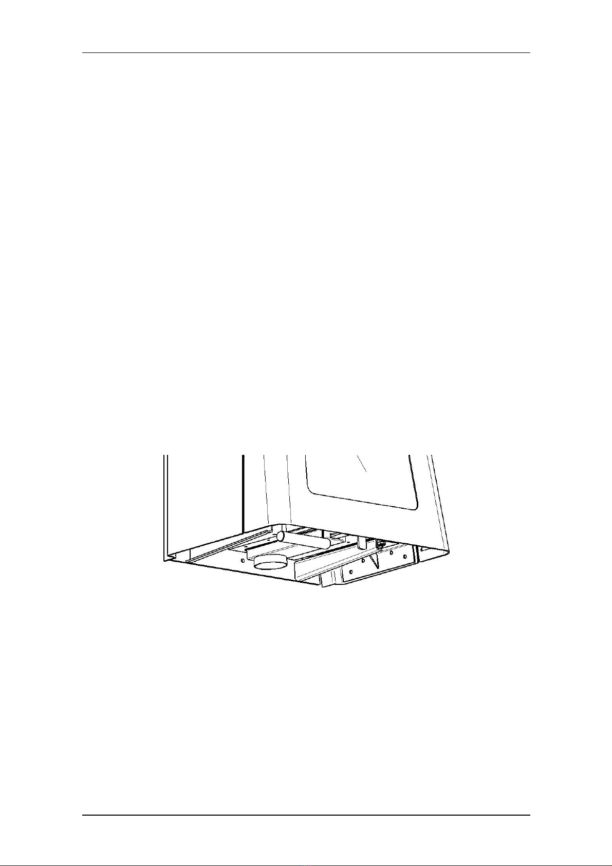
• De Yuna is uitgevoerd met een a sluitbare buitenluchtaansluiting diameter 80 mm. Deze
kan worden aangesloten met een lexibele hittebestendige pijp zodat er ona hankelijk van de
opstelruimte verbrandingslucht van buiten kan worden gehaald.
• Controleer voor gebruik o de vermiculietplaten en de keerplaten in de kachel goed geplaatst
zijn (zie gebruikshandleiding).Verbeter zo nodig de positie van de platen.
• Leg de eventuele vloerplaat onder de haard.
Indien de haard wordt gestookt met een vermogen < 9 KW o wanneer de schoorsteen langer is
dan5 meter o een geringe warmteweerstand hee t dient u de enkelwandige aansluitpijp over de
juiste lengte met geschikt isolatie materiaal te isoleren. Hierdoor wordt het vermogen gereduceerd
en/o de rookgastemperatuur verhoogd.

Dik Geurts
9
6. STOKEN
Zie de Gebruikershan lei ing, hoo dstuk 5, voor het aansteken en stoken van de haard.
7. OPLEVERING
U dient de gebruiker vertrouwd te maken met de haard. U dient haar/hem te instrueren over
onder meer de ingebruikname, het stoken en het onderhoud.
• Instrueer de gebruiker over de haard.
• Wijs er bij ingebruikname op, dat:
− bij de eerste keer stoken vluchtige componenten uitdampen uit lak, materialen e.d.;
− de ruimte goed wordt geventileerd.
• Wijs op de noodzaak om het rookgaskanaal minstens één keer per jaar te laten
inspecteren en reinigen door een specialist.
• Overhandig de gebruiker de gebruikershandleiding én de installatiehandleiding (de
installatiehandleiding dient bij het toestel bewaard te blijven).
8. ONDERHOUD
In de Gebruikershan lei ing wordt in Hoo dstuk 6, Onderhoud, een aantal tips/instructies
gegeven voor het onderhoud van de haard. Tevens is vermeld hoe een aantal onderdelen
vervangen kan worden.
9. STORINGEN
In de Gebruikershan lei ing, hoo dstuk 7, staat een tabel met een overzicht van storingen die
kunnen optreden, de mogelijke oorzaak en de oplossing.
Bijlage 1 Meegelever e on er elen
In de onderstaande tabel staan de onderdelen vermeld die met het toestel worden meegeleverd.
Tabel 1: Meegeleverde onderdelen
on er eel aantal
Installatiehandleiding 1x
Gebruikershandleiding 1x
Handschoen 1x
Asschep 1x
Spuit lacon ruitenreiniger 1x
Spuitbus met hittebestendige lak 1 x
Bevestigingsmaterialen 1 x

10
Bijlage 2 Technische gegevens
In de onderstaande tabel staan de technische gegevens vermeld. De omschreven rendementen
en emissies in de technische gegevens kunnen worden behaald volgens de testmethode zoals
beschreven in de Europese Norm 13240.
Tabel 2: Technische gegevens
Bijlage 3 Lijntekening
Type Yuna
Brandsto Hout
Werking Intermitterend
A stand tot brandbare materialen 700 mm
Rookgastemperatuur 128 ºC
Rookgasdebiet 4,8 g/s
Trek rookgaskanaal 12 Pa
Nom. Vermogen 9,5 kW
Rendement 91 %
Diameter uitgang 180 mm
Gewicht 132 kg

Dik Geurts
11

12
Contents
Page
PREFACE 13
1. INTRODUCTION 13
2. EC Conformity Declaration Yuna 14
3. SAFETY 15
3.1 General 15
3.2 Regulations 15
3.3 Precautions /sa ety instructions during installation 15
4. REMOVING THE PACKAGING 15
5. INSTALLATION 16
5.1 Regulations 16
5.2 Flue duct 16
5.3 Placing the ire 16
6. BURNING 19
7. DELIVERY 19
8. MAINTENANCE 19
9. MALFUNCTIONS 19
Appen ix 1 Inclu e parts 19
Appen ix 2 Technical ata 20
Appen ix 3 Line rawing 20

Dik Geurts
13
PREFACE
As a manu acturer o ires, Dik Geurts is developing products in accordance with the highest
possible quality, per ormance and sa ety requirements. As a result, you are guaranteed to enjoy
their bene its or years to come.
This ire has been provided with a CE mark. Wood burning ires that comply with the essential
requirements or sa ety, environment and energy consumption o the European construction
products directive, are entitled to carry the CE mark.
The ire will be supplied with two manuals: the installation manual and the user manual. The user
manual will provide you with the in ormation you need to operate the ire in a proper and sa e
way.
Care ully read the user manual be ore using the ire. Keep the user manual AND the installation
manual in a sa e place. As the user, you are only allowed to per orm work described in the user
manual. Any other work requires a competent installer.
The installation manual will provide you with the in ormation you need to install the ire in such a
way that it will work properly and sa ely. This manual discusses the installation o the ire and the
regulations that apply to the installation. It also provides you with the technical speci ication o the
ire. In case o questions or doubts, please contact your installer.
Please carefully rea an use this installation manual.
The ollowing symbols are used in the manual to indicate important in ormation:
• Work to be per ormed
Caution You need these instructions to prevent ire, personal injury or other
serious damages.
After elivery, you shoul give the user manual AND this installation manual to the user.
1. INTRODUCTION
Congratulations on the purchase o this Dik Geurts ire. The ire has an ingenious burning system
that ensures e ective combustion and optimum e iciency. The combustion chamber is lined with
vermiculite plates. At the top you will ind a so called ba le plate to increase the e iciency. The
Yuna is provided with a slide or both primary and secondary air supply. The Yuna is equipped
with an (optional) connection to the open air. The ire is only suitable to be illed with wood or
wood briquettes.

14
2. EC CONFORMITY DECLARATION YUNA
The undersigned, representative o :
Manufacturer:
Dru Verwarming BV
Postbus1021,NL-6920 BA Duiven
Ratio 8, NL-6921 RW Duiven
Hereby declares that the Dru Verwarming BV issued wood ired heating appliance was designed
and constructed in such a way that the appliance complies with the essential requirements o the
Construction Products Directive and that it is produced and distributed in accordance with the
requirements o the Belgian Royal Decree o 12 October 2010 or the regulation o minimum
requirements concerning the e iciency and emission levels o polluting substances or solid uel
heating appliances.
Pro uct: Wood burning heating appliance made rom sheet steel
Type: Yuna
Applicable EEC irectives: 89/106/EEC
Applie harmonize stan ar s: NENEN13240 NEN/EN13240/A2
Notifie bo y: SGS Nederland BV, Reg.nr. 0608 Leemansweg 51, NL –
6827 BX Arnhem
Distinguishing product eatures
Internal measures by the company guarantee that appliances produced in series comply with the
essential requirements o the prevailing EEC directives and the standards derived rom them.
This declaration will lose its validity i adjustments are made to the appliance, without prior written
permission by Dru Verwarming BV.
On behal o Dru Verwarming BV
M.J.M Gelten
General director
Feature Result
Type Yuna
Fuel Wood
Operation Intermittent
Distance rom
Combustible material
700mm
Emission o
Combustion products
CO emission:
0,10vol.%(at
13%O
2
)
Flue gas temperature 128ºC
Nominal output 9,5kW
E iciency 91%
Fire sa ety compliant
Release o harm ul none
substances
Sur ace temperature compliant
Mechanical strength compliant
Report EZKA/10/0121

Dik Geurts
15
3. SAFETY
3.1 GENERAL
Caution Care ully read this chapter on sa ety, be ore you start per orming
installation or maintenance work;
Please observe the general regulations and the precautions/sa ety
instructions in this manual.
3.2 REGULATIONS
Please install the appliance in accordance with the applicable European, national, local and
constructional (installation) regulations. In the Netherlands, the Building Regulations applies.
3.3 PRECAUTIONS / SAFETY INSTRUCTIONS DURING INSTALLATION
Care ully observe the ollowing precautions/sa ety regulations:
• You should only install and maintain the ire i you are a competent and recognized wood
burning appliances installer;
• Suspend the ire rom a wall with su icient load bearing strength;
• Suspend the ire and/or place the lue pipes in ront o a wall made o noncombustible
material;
• I you discover lammable materials apply su icient heat resistant isolation material;
• Always place the ire and/or the lue pipes at a minimum distance o 700 mm rom
combustible objects and/or materials;
• Mount the ire on top o a protective loor plate, in case o a combustible loor. The loor
plate made o noncombustible material should extend at least 300 mm at the ront o the
ire, and it should be at least 300mm wider than the ire;
• Connect the ire to a suitable lue duct;
• Have the lue duct inspected and cleaned in advance, by a certi ied chimney sweeping
company;
• Do not make any changes to the ire yoursel ; only replace parts by original parts;
• Make sure there is su icient ventilation in the room where the ire is installed.
4. REMOVING THE PACKAGING
Note the ollowing items when removing the packaging:
• check the appliance or transportation damage, neever install a damaged ire;
• check i the box with parts is complete.
In appendix 1 / table 1 you can see which parts you should have a ter removing the packaging;
• as some parts may have shi ted in transit, check the position o the ba le plate and the
vermiculite plates.
• check the operation o the air slide, door closure and, i applicable, the rotation
mechanism;
• i necessary, contact your supplier;
• dispose o packaging in accordance with local regulations.

16
5. INSTALLTION
5.1 REGULATIONS
• Pleas install the ire in accordance with the applicable national, local and constructional
(installation) regulations.
• Observe the regulations/instructions in this manual.
5.2 FLUE DUCT
The ollowing requirements apply to the lue duct:
− the lue duct must be inspected in advance by a specialist;
− the lue duct must be suitable or connection to a wood stove;
− the ire must be connected to a single, unshared ire duct;
− the lue duct must be clean and gastight;
− the bend in the lue duct may amount to a maximum o 1.5 meters;
− the diameter o the lue duct must be equal to the diameter o the stove's lue exhaust;
− the draught in the lue duct must be at least 12 Pascal;
− in case o a duct with a draught that is too strong, it may be necessary to install a lue valve;
− lue pipes must be placed in such a way that they drain towards the stove;
− the lue duct must be sel supporting and may not rest on the stove;
5.3 INSTALLING THE FIRE
Install the ire as ollows:
Caution - Do not make any changes to the ire;
- suspend the ire rom a wall with su icient load-bearing strength;
- suspend the ire rom a wall made o non-combustible material;
- always place the ire and/or the lue pipes at a minimum distance o 700
mm rom combustible objects and/or materials;
- place a ire-resistant loor plate under the ire, extending 300 mm in ront o
the stove, i it is suspended above a loor made o combustible material;
- do not cover the ire and/or do not wrap it in an insulation blanket or any
other material;
- observe the requirements or the lue duct, as stated in paragraph 5.2.

Dik Geurts
17
Fig. 1 Fig. 2
Fig. 3 Fig. 4

18
• Determine the location o the Yuna; the dimensions can be ound in appendix 2 technical
ata.
• The height under the ire ( ig 1, H) is normally approximately 20 to 42 cm, this dimension
also depends on the ceiling height, see the line drawing in appendix 3 with dimensions.
• The ire is suspended by means o a wall plate ( ig 1, 2), determine dimension L ( =
underside wall plate)
• Level the wall plate with the supplied M8 bolts and wedge cases ( ig 1, 1-3-4).
• Suspend the ire over the wall bracket, align the ire under the duct.
• Secure the ire with the supplied outside thread anchors ( ig1 , 5)
• Then place the wall plate ( ig 2 , 6) on the cams, make sure everything is neatly vertically
aligned, using the supplied outer thread anchors or plugs. In case o a rear connection, use
one o the recesses ( ig 2, 7)
• Place the lue pipe ( ig 3), secure it with a plate screw ( ig 3, 10)
• Slide the adjustable ceiling plate ( ig 4 ,12) in the top cover ( ig 4, 11)
• Hang the top cover incl. ceiling plate with cams in the recesses o the upper plate ( ig 2, 6)
• Mark out the ceiling plate and attach it with the supplied screws and plugs ( ig 4, 14-15)
• Secure the top cover with the supplied bolts m6 ( ig 4, 13)
• Check whether everything is aligned. I necessary, the side plates can be adjusted with the
socket screws and the door by means o the lange nuts.
• The Yuna is made with a lockable external air connection with a diam. o 80 mm. It can be
connected with a lexible heat-resistant pipe, so that combustion air can be drawn rom
outside, independent o the installation room.
• Check, prior to use, whether the vermiculite plates and the ba le plates are mounted
correctly in the ire (see user manual). I necessary, correct the position o the plates.
• Place the possible loor plate under the ire.
I the ire is ired with a capacity o < 9 KW, or i the chimney is more than 5 metres long, or has a
lower heat resistance, you will have to insulate the single wall connection pipe with suitable
insulation material, over the correct length. As a result, the capacity is reduced and/or the lue gas
temperature is increased.

Dik Geurts
19
6.
BURNING
See the User Manual, chapter 5, or lighting and burning the ire.
7. DELIVERY
You must explain to the user how she/he should operate the ire. You should instruct her/him or
instance on using the appliance or the irst time, heating and maintenance.
• Instruct the user on the ire.
• When the appliance is started or the irst time, point out that when the appliance is
heated up or the irst time, volatile components evaporate rom paint, materials, etc.
• Point out that it is necessary to have the lue duct inspected and cleaned by a specialist,
at least once per year.
• Give the user manual AND the installation manual to the user (the installation manual
should be kept near the appliance).
8. MAINTENANCE
There are a number o tips/instructions on the maintenance o the ire in Chapter 6, Maintenance
o the User Manual. This also explains how a number o parts can be replaced.
9. MALFUNCTIONS
In chapter 7 o the User Manual you will ind an overview o mal unctions that might occur, the
possible causes and the remedies.
Appen ix1 Parts supplie
In the ollowing table you can ind the parts that are supplied with the appliance.
Table1:Parts included with the delivery
part quantity
Installation manual 1x
User manual 1x
Glove 1x
Ash pan 1x
Glass cleaner spray bottle 1x
Spray can o heat resistant paint 1x
Fastening materials 1x
Table of contents
Languages:
Other Dru Heater manuals