ASROCK IBOX-230 User manual

iBOX-230
User Manual
Version 1.0
Published March 2018

Important Safety Instructions
Pay close attention to the following safety instructions before performing any of
the operation. Basic safety precautions should be followed to protect yourself from
harm and the product from damage:
• Operation of the product should be carried out by suitably trained, qualied, and
certied personnel only to avoid risk of injury from electrical shock or energy hazard.
• Disconnect the power cord from the wall outlet when installing or removing main
system components, such as the motherboard and power supply unit.
• Place the system on a stable and at surface.
• Use extreme caution when working with high-voltage components.
• When handling parts, use a grounded wrist strap designed to prevent static discharge.
• Keep the area around the system clean and clutter-free.
• Keep all components and printed circuit boards (PCBs) in their antistatic bags when
not in use.
• Handle a board by its edges only; do not touch its components, peripheral chips,
memory modules or contacts.
e terms HDMI®and HDMI High-Denition Multimedia Interface, and the HDMI
logo are trademarks or registered trademarks of HDMI Licensing LLC in the United
States and other countries.

Contents
Chapter 1 Introduction 1
1.1 Package Contents 1
1.2 Product Specications 2
1.3 Block Diagram 4
Chapter 2 Product Overview 5
2.1 Front View 5
2.2 Rear View 6
2.3 Inside View 7
Chapter 3 Hardware Installation 8
3.1 How to Remove the Bottom Case 8
3.2 How to Install the Mini PCIe Card 9
3.3 How to Install the mSATA SSD 10
3.4 How to Install the 2.5-inch Hard Drive 11
3.5 How to Install the Memory Modules
(DDR3 Low Voltage (1.35V)) 13
3.6 How to Install the VESA Bracket 14
3.7 Positions of the iBOX-230 15
Chapter 4 Motherboard 16
4.1 Motherboard Layout 16
4.2 Motherboard Specications 18
4.3 Jumpers Setup 20
4.4 Onboard Headers and Connectors 22

iBOX-230
PB 1
English
Chapter 1 Introduction
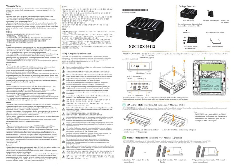
1.1 Package Contents
• iBOX-230 Barebone System with:
iBOX-230 Chassis
Motherboard (pre-installed)
*e barebone system does not include memory, hard drive and mSATA SSD.
• Power Adapter (65W/19V) & Power Plug
• SATA Data and Power Cable
• mSATA Screw
• VESA Mount Bracket & Screw Package
• Support CD
• Quick Installation Guide
Because the hardware specications might be updated, the content of this documentation
will be subject to change without notice.
If any items are missing or appear damaged, contact your authorized dealer.

2 3
English
1.2 Product Specications
iBOX-230 Barebone
CPU Intel® Apollo SoC Processor N4200/N3350/E3940
(Up to 2.5/2.4/1.8 GHz)
OS N/A
Chipset SoC
Memory Supports Dual Channel DDR3L SO-DIMM 1867, up to 8GB
HDD
N/A
1 x Full Size (Colay with Mini-PCIe)
N/A
1 x Full/Half Size
(Supports PCIe x1 & USB device)
1 x Full Size
(Colay with mSATA)
LAN Gigabit LAN
WiFi Optional
Audio Realtek ALC887, HD codec
Front I/O 2 x RJ45, 2 x USB 2.0, 1 x HDMI 1.4, 1 x VGA, 1 x Mic-in,
1 x Line-out
Rear I/O 2 x USB 3.0, 2 x COM
eMMC
mSATA
Mini-PCIe
M.2

iBOX-230
2 3
English
Power Unit 9V~36 V DC-in
Dimension 135mm (W) x 44.5mm (H) x 110mm (D)
VESA Bracket included , supports 75 x 75 and 100 x 100 mm
Volume
(Liters) 0.6L
Operating
Temperature 0°C~50°C

4 5
English
1.3 Block Diagram
5
5
4
4
3
3
2
2
1
1
D D
C C
B B
A A
Apollo Lake --- SBC-230
VRD on Board
SATA3_1
128-bit Dual-Channel Memory x 2 Slots
DDR3L 1867
Channel A
PCIe x1
Realtek
Audio Codec
CH7511B
PTN3356
USB3.0 x22 Rear USB3.0 ports Type -A
Gb LAN
RJ45 #1
DDI_0
eDP Con.
HDMI
DDR3L 1867
Channel B
SPI
SPI FLASH
24MHz
SATA 3.0 BUS
LPC
SIO
Nuvoton
NCT6106
Apollo Lake SoC
Intel
Intel
i210
Intel
i210
Gb LAN
RJ45 #2
PCIe x1 / USB 2.0 x1 Mini PCIe(Full/half size)
USB 2.0 x4 Front header USB2.0 ports *4
PCIe x1
SATA 3.0 BUS
NXP CBTL04083BBS
(PCIe Switch)
USB 2.0 x1
Mini PCIe (Full size)
TPM
Serial Port x4
- Internal Header *1 (RS232/422/485)
- Internal Header *3 (RS232 only)
FAN x1
DIO Port
LVDS Con.
(2-ch/24bits)
eDP
DDI_1
DP to CRT
CRT VGA
1.8V/64Mb
ALC887
Realtek
Audio Amplifier
ALC122
Line
Out MIC
SPK (Header)
PCIe x1
TS3DV642
RUAR

iBOX-230
4 5
English
Chapter 2 Product Overview
is chapter provides diagrams showing the location of important components of
the iBOX-230.
2.1 Front View
1 2 3 4 5
No. Description
1On-/o Switch
2Power LED
3HDD LED
4 2 x COM Ports
5 2 x USB 2.0 Ports (Type A)

6 7
English
2.2 Rear View
23 4 5 6 87 1091
No. Description
1 Kensington Lock Slot
2Antenna Port
3Microphone (Pink)
4 Line out (Green)
5 2 x RJ-45 Ports
6 HDMI Port
7 2 x USB 3.0 Ports (Type A)
8VGA Port (VGA1)
9 DC Jack (DC IN)
10 Antenna Port
* ere are two LEDs on the LAN port. Please refer to the table below for the LAN port LED indications.
Activity / Link LED Speed LED
Status Description Status Description
O No Link O 10Mbps connection
Blinking Data Activity Orange 100Mbps connection
On Link Green 1Gbps connection
ACT/LINK LED
SPEED LED
LAN Port

iBOX-230
6 7
English
2.3 Inside View
4
2
13
No. Description
1mSATA Slot
2 Mini PCIe Slot
3SO-DIMM Sockets
4 Hard disk drive tray (compatible with 2.5" SATA HDD)
SO-DIMM memory, hard drive and mSATA SSD are not included with this system.

8 9
English
Chapter 3 Hardware Installation
is chapter helps you install or remove important components.
3.1 How to Remove the Bottom Case
1. Remove the four screws on the bottom case.
2. en li up and remove the bottom panel.
2
1

iBOX-230
8 9
English
3.2 How to Install the Mini PCIe Card
1. Locate the Mini PCIe slot on the motherboard.
2. Carefully insert the Mini PCIe card into the slot.
3. Tighten the screw to secure the PCIe card to the motherboard.

10 11
English
3.3 How to Install the mSATA SSD
1. Locate the mSATA slot on the motherboard.
2. Carefully insert the mSATA SSD into the slot.
3. Tighten the screw to secure the mSATA SSD to the motherboard.

iBOX-230
10 11
English
3.4 How to Install the 2.5-inch Hard Drive
1. Remove the four screws on the bottom case. en li up and remove the bottom panel.
2. Attach the HDD cage to the bottom panel and secure it using the four screws.
en connect the SATA cable to the HDD.
2
1

12 13
English
3. en reinstall the bottom panel.
1
2

iBOX-230
12 13
English
3.5 How to Install the Memory Modules
(DDR3 Low Voltage (1.35V))
1. Carefully insert the SO-DIMM memory modules into the slot at a 30-degree angle.
2. Push down until the modules snap into place.
1. e iBOX-230 requires DDR3L SO-DIMM (1.35V).
2. For dual channel conguration, you always need to install identical (the same brand,
speed, size and chip-type) DDR3L SO-DIMM pairs.
e SO-DIMM only ts in one correct orientation. It will cause permanent damage to the
motherboard and the DIMM if you force the DIMM into the slot at incorrect orientation.

14 15
English
3.6 How to Install the VESA Bracket
1. Attach the two screws to the base of the iBOX-230.
2. 2. Attach the VESA Bracket to the rear of a compatible display using the four screws.
*Choose mounting holes depending on the mounting hole pattern of your LCD screen
(75 mm × 75 mm or 100 mm × 100 mm).
3. Mount the iBOX-230 by sliding it into place.

iBOX-230
14 15
English
3.7 Positions of the iBOX-230
e iBOX-230 can be placed in vertical or horizontal position.
*Please note that keeping the iBOX-230 in a vertical position will ensure better cooling
performance.
USB Power On Function:
USB Power On Function allows system power on via USB keyboard/mouse.
is function is useful when the iBOX-230 is mounted behind your display/TV.
To enable USB Power On Function:
1. Enter BIOS by pressing <F2> or <Del> during device startup.
2. Select “Advanced > ACPI Conguration” from the menu.
3. Set “USB Keyboard Power On” and “ USB Mouse Power On” settings to “Enabled”.
4. Press F10 to Save and Exit.
Horizontal Position Vertical Position Wall-mounted

16 17
English
Chapter 4 Motherboard
4.1 Motherboard Layout
BIOS
Chip
1
JGPIO1
1
LPC1
SPEAKER1
1
LAN1
HDMI1
PANEL1
HDLED RESET
PLED PWRBTN
1
SATA_PWR1
LVDS 1
1
1
BLT_VOL1
USB3.0
T: USB3
B: USB2
COM1 COM2 COM3 COM4
PNL_PWR1
1
SATA3 _1
LAN2
1
DC_IN1
VGA1
MicIn
Line Out
BKT_PWR1
1
CLRMOS2
1
11
8
10
16
17
14
18
21 19
27 25
29
28
DDR3_A1 (SupportDDR3L Only)
DDR3_B1 (SupportDDR3L Only)
Industrial
1
BL2
BLT_PWR1
1
1
BL1
1 1
EDP_LVDS_J1
PWR_JP1
1
EDP_LVDS_J2
1
HD_AUDIO1
FAN1
SET_CM1
1
MSATA_SEL1
1
JGPIO_PWR1
1
1
USB2_6_7
1
USB2_4_5
CLRMOS1
1
JGPIO_SET1
1
1
CI1
1
CI2
BUZZ1
1
SBC-230
mini-PCIe/mini-SATA
mini-PCIe
Other manuals for IBOX-230
1
Table of contents
Other ASROCK Industrial PC manuals