Erreka RINO-I Operating instructions

6
RINO-I
Quick installation and programming guide English
WARNING
This quick guide is a summary of the complete installation manual. The manual contains safety warnings and
other explanations which must be taken into account. The most recent versions of this guide and the
installation manual are available at the "Downloads" section on Erreka's website.
http://www.erreka-automation.com
The options and functions described in this guide apply for the firmware version indicated on the circuit. The
firmware, as part of a process of continuous improvement, is subject to new functionalities or upgrades being
included as a result of new versions which are not necessarily compatible with previous ones. For this reason,
some options or functions may differ or be unavailable if your firmware is older than shown in this guide.
E274D
Electrical wiring
A: Main power supply
B/E: Flashing light with antenna
C: Photocells (Tx / Rx)
D: Pushbutton/wall key
Elements of the complete installation
Assembly levels (mm)
Photocells
SG.A: opening photocell,
enable: C410
enable testing: C411
SG.C: closing photocell,
enable: C510
enable testing: C511
enable with opening
disabled: C520
enable testing with
opening disabled: C521
D138A
2
D138B
2
3
Unlocking
Locking for motorised operation:
•Turn the handle (2) anti-clockwise 270°
without forcing it.
•Turn the key (1) anti-clockwise and remove.
•Push the cylinder (3) inward and manually
move the gate to interlock it in the drive
mechanism.
Unlocking Locking
Unlocking for manual
operation:
•
Insert the key (1) and turn
clockwise without forcing it.
•Turn the handle (2)
clockwise 270°, through to
the stopper but without
forcing it.
MSM-046/00 Firmware V1.05 or later

7
P274Z
LB/ LR
A.T. (ST1)
COM
SG.C (FT1)
COM
A.P. (ST2)
SG.A (FT2)
AUX
(12Vdc)
FT
RIS1000EIC: 230V/50-60Hz
RIS1000EICM: 125V/50-60Hz
N
L
T
G1
G2
COM
60W max
(1.250/2.300W max)
COM
G2
G1
3~
M
1~
M
J7
Pos 1
Pos 2 J7
DL26
F1
F2
F3
F4
General connections
(photocell without
testing)
(photocell with testing)
(1250/2300W max)
60W max
red
white
green
brown
black
gray
Do not use acapacitor
for the motor.
F1 Main Fuse (3A)
F2 Primary Fuse (0.5A)
F3 Secondary Fuse (1A)
F4 Peripheral Fuse (0.315A)
DL26 DC bus LED
M274C
A
B
ESC ENTER
P4
P3
D1 and D2:
CL8º (static) Gate closed
CL88 (flashing) Gate closing
OP88 (static) Gate open
OP88 (flashing) Gate opening
PC88 (flashing) Pedestrian door closing
PO88 (static) Pedestrian door open
PO88 (flashing) Pedestrian door opening
XX88 (countdown) Gate on standby
PA88 (static) Pause (operation not complete)
StOP Operator unlocked
HEAt Excessive heating inverter module
COç
Communication failure with inverter module
D3 and D4 (during operation):
88ºÂ8FT2 activated 888ºÂFT1 activated
88º@8Flashing light 888º@
green traffic light activated
88º+8Internal FCC activated 888º+Internal FCA activated
88º?8
2nd radio channel (or RSD)
888º?1st radio channel signal
88º-8External FCC activated 888º-External FCA activated
88º¨8ST2 activated 888º¨ST1 activated
88ºâ8LG activated 888ºâred traffic light activated
D3 and D4 (in case of failure):
88C4 Opening safety device activated
88C5 Closing safety device activated
88C9 Safety strip enabled
88E1 Encoder motor shutdown
88F1 Force limit exceeded
Display indications
The display can be placed in position “B” for
easier programming. Once finished, return to
"A” position before positioning the frame.
P3: communication with inverter module
P4: encoder active

8
ESC ENTER
P274I
ESC ENTER
P274J
ENTER
ESC
P274Y
P274ZZ
ESC ENTER
Turning direction change and check (C1)
ESC ENTER
P274H
ESC ENTER
P274K
ENTER
ESC
P274V
ENTER
ESC
P274W
This operation is only necessary if the operator opens the leaf instead of closing it when making a reset (rS).
1 Press ENTER, with
the display showing
rSXX (rSºÂ8, rSºâ8,
rS8º@, rS8º?, etc).
ESC ENTER
ESC
P274X
ESC ENTER
P274B
ESC ENTER
P274C
ESC ENTER
P274D
I
II
P274E
5
ESC ENTER
P274F
ESC ENTER
P274G
Total opening radio code programming P1 (with RSD receiver only,
C801
)
If a receiver other than RSD
is used, see the
corresponding instructions.
Select the
option
C801
(RSD receiver) before
starting programming.
Pedestrian opening radio code programming,
P2
(with RSD receiver only,
C801
)
This procedure is the same as for total opening, but using parameter P2 instead of P1.
1 Press ENTER, with the
display showing rSXX
(rSºÂ8, rSºâ8,rS8º@,
rS8º?, etc).
ESC ENTER
P274B
ESC ENTER
P274M
ESC ENTER
P274N
ESC ENTER
P274O
ESC ENTER
P274P
P274Q
ENTER
ESC
Open/close programming (P3)
11 Start closing by pressing the
transmitter, ST1 or ^.
12 Start slowdown by pressing the
transmitter, ST1 or ^.
13 Wait for it to come to a stop at the
end of travel.
Once programming is complete,
the parameter A6XY is shown,
indicating the suggested
currents for normal speed (X)
and fast speed (Y). This can be
modified if required.
1 Press ENTER, with the
display showing rSXX
(rSºÂ8, rSºâ8,rS8º@,
rS8º?, etc).
Before programming, carry out
an opening and closing
movement at normal and slow
speed in order to detect the
corresponding currents
(parameter A6XY).
8 Start opening by pressing the
transmitter, ST1 or ^.
9 Start slowdown by pressing the
transmitter, ST1 or ^.
10 Wait for it to come to a stop at the end
of travel.
Pedestrian opening is programmed using the parameter F3 (see “Complete programming chart”).
14 15
ESC ENTER
P274S
P274U
ESC ENTER

9
D1 D2 Parameter D3 D4 Pre-set option Options or values
C1Motor turning direction 01x
02
3Type of gate 02x Sliding gate
03 Up&over door, with shadow function
4Opening safety device (photocell or
strip)
00x Device not installed
10 Device without testing
11 Device with testing
5Closing safety device (photocell or
strip)
Closing photocell with C520 or C521,
also prevents the start of gate opening
00x Device not installed
10 Device without testing
11 Device with testing
20 Device without testing
21 Device with testing
7Encoder and limit switches
(when using external limit switches,
connect them to the corresponding
terminals of the control board)
00 No encoder or limit switches
02 With internal limit switches
04x With encoder and internal limit switches
06 With external limit switches
07 With encoder and external limit switches
8Radio receiver 01 RSD card (frame, not decoder)
02x Twin-channel decoder card
9Safety strip type 01x Contact edge
02 Resistive edge
ASlowdown 00 No slowdown
01x Slowdown in opening and closing
02 Slowdown in opening
03 Slowdown in closing
P1Total opening radio code
programming
oç
2Pedestrian opening radio code
programming
oç
3Gate travel programming oç
F1Key command using ST1 and ST2
pushbuttons
00 ST1 and ST2 without effect, key commands
are made by radio (channel 1: total
opening-closing, channel 2: pedestrian
opening-closing)
01x ST1 total opening-closing, ST2 pedestrian
opening-closing
02 ST1 total opening, ST2 total closing
03 Dead-man mode
04 Dead-man mode in closing
2Operation mode (semi-automatic or
automatic) and stand-by time (in
seconds) in automatic mode
0...5ÿ 0...900 00: semi-automatic mode
01: automatic mode and stand-by time 1
second; ...
59: automatic mode and stand-by time 59
sec.;
1ÿ0: 1 min. 0 secs.; ....; maximum 4 minutes
3Pedestrian opening 0...90...940 00: Pedestrian opening is not carried out
01: 1% of total opening
12: 12% of total opening
99: 99% of total opening (equivalent to
100%)
4Pedestrian closing operation mode
(semi-automatic or automatic) and
stand-by time (in seconds) in automatic
mode
0...5ÿ 0...900 00: semi-automatic mode
01: automatic mode and stand-by time 1
second; ...
59: automatic mode and stand-by time 59
sec.;
1ÿ0: 1 min. 0 secs.; ....; maximum 4 minutes
Complete programming chart

10
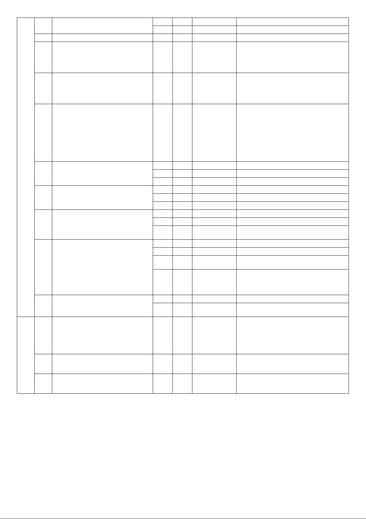
A0Flashing light 01x No pre-warning, static output
02 With pre-warning, static output
1Garage light time 0...5ÿ 0...903 59= 59 secs; 2ÿ5 = 2 min. 50 secs, etc
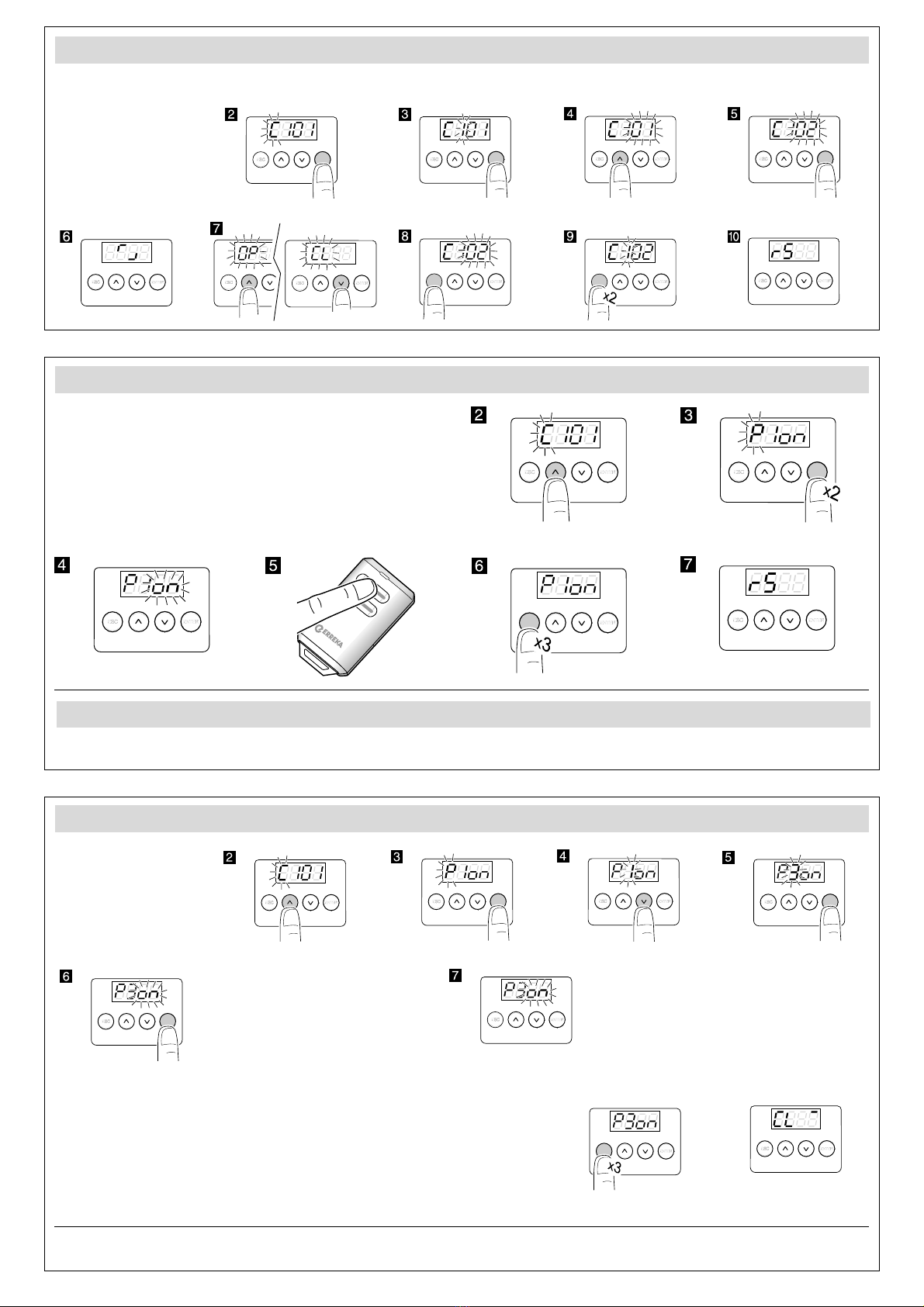
2Gate speed
The open/close run must be
reprogrammed whenever this
parameter is changed
01...903 01: minimum speed (40Hz);
02: 45Hz, 03: 50Hz, 04: 55Hz, ...
09: maximum speed (80Hz)
3Slowdown speed
The open/close run must be
reprogrammed whenever this
parameter is changed
01...903 01: minimum speed (21Hz);
02: 22Hz, 03: 23Hz, 04: 24Hz, ...
09: maximum speed (29Hz)
6Maximum entrapment current (each
value equivalent to 0.5A)
The digit D3 can be used to adjust
current to normal speed
The digit D4 can be used to adjust
current to slow speed
0...90...900 00: disabled;
01: disabled at normal speed and 0.5A at
slow speed;
10: 0.5A at normal speed and disabled at
slow speed; ...;
65: 3A at normal speed and 2.5A at slow
speed;...;
99: 4.5A at normal and slow speed
7Closing photocell crossed during
standby (in automatic mode only)
00 No effect
01 Immediate closing after crossing
02x Restart standby time
8Effect of pushbuttons (ST1, ST2) during
stand-by time (in automatic mode only)
00 No effect
01 Cause immediate close
02x Restart stand-by time
9Opening mode 01 Collective opening
02x Semi-automatic alternative shutdown
03 Automatic alternative shutdown (only in
automatic mode, F2 K00
bUsing the EPS1 card connector
For parameters Ab02 and Ab03, use
the EPS1 card and bridge the network
input cable connectors instead of
disconnecting them from the network.
00x use for standard traffic light
01 use for brakes
02 NC contact with gate open (L1-COM) and
gate closed (L2-COM)
03 impulse 1 second Open (L1-COM) when
starting opening and Close (L2-COM) when
starting closing. Allows another board to be
activated
ESpecial functions 00x no special function
02 industrial
(1.5s delay in shutdown and reversing)
ç0Programming lock key
Be sure to remember any key used, for
future access to programming
X X 0000 The preset option is 0000 (no key). If any
figure is changed, this is considered a key.
Select the required key (starting with D1)
using UP and DOWN. Press ESC to cancel or
ENTER to confirm and move to D2, and so
on.
1Operations carried out (total counter) XX Indicates the hundreds of cycles completed
(for example, 68 indicates 6,800 cycles
completed)
2Operations carried out (partial counter,
restarts with ST1 and ST2)
XX Indicates the hundreds of cycles completed
(for example, 68 indicates 6,800 cycles
completed)
Other manuals for RINO-I
1
Table of contents
Other Erreka Door Opening System manuals
Popular Door Opening System manuals by other brands

WSS
WSS SPRINT NOVA 80 Assembly and operating instructions

Assa Abloy
Assa Abloy Corbin Russwin DC8210 Series installation instructions

Raynor
Raynor ControlHoist 2.0 STANDARD Installation instructions and user guide

JCM Technologies
JCM Technologies KEEROLL user manual

golmar
golmar K-ACCESS PAC-90 quick start guide

Assa Abloy
Assa Abloy Norton 9500 Series installation instructions