manuals.online logo
Brands
  1. Home
  2. •
  3. Brands
  4. •
  5. Astral Pool
  6. •
  7. Water Filtration System
  8. •
  9. Astral Pool EASY SALT ES-70 Manual

Astral Pool EASY SALT ES-70 Manual

SALT ELECTROLYSIS SYSTEM
SYSTÈME D’ÉLECTROLYSE SALINE
SISTEMA DE ELECTROLISIS SALINA
SALZ-ELEKTROLYSE- SYSTEM
SISTEMA DE ELECTRÓLISE SALINA
INSTALLATION AND MAINTENANCE MANUAL
MANUEL D’INSTALLATION ET D’ENTRETIEN
MANUAL DE INSTALACION Y MANTENIMIENTO
MANUALE DI INSTALLAZIONE E MANUTENZIONE
EINBAU-UND BETRIEBSANLEITUNG
MANUAL DE INSTRUÇOES E MANUTENÇAO
Model. ES-70
53799
ES-90
53800
ES-180
53801
SISTEMA PER L’ELETTROLISI DEL SALE
EASY SALT
ES-70+
53802
ES-90+
53803
ES-180+
53804
1
ENGLISH ___________________________________________________________________
IMPORTANT: The instruction manual you are holding includes essential information on the safety measures to be implemented for
installation and start-up. Therefore, the installer as well as the user must read the instructions before beginning installation and start-up.
Keep this manual for future reference.
Disposal of waste electrical and electronic domestic systems in the European Union
All the products marked with this symbol indicate that the product shall not be mixed or disposed with your
household waste at their end of use. It is responsibility of the user to eliminate this kind of wastes depositing them in
a recycling point adapted for the selective disposal of electrical and electronic wastes. The suitable recycling and
treatment of these wastes contributes in essential way to the preservation of the Environment and the health of the
users. For further information regarding the points of collection of this type of wastes, please contact to the dealer
where you acquired the product or to your municipal authority.
The instructions given in this manual describe the operation and maintenance of EASY SALT ES-70, ES-90 and DOM180 Salt Electrolysis
Systems, and their corresponding versions with PH/ORP control extensions (EXT-1). For optimum performance of the EASY SALT Salt
Electrolysis Systems, we recommend you to follow the instructions given below:
1. CHECK THE CONTENTS OF THE PACK: ___________________________________________________________________________
You should find the following elements inside the box:
1. Power supply.
2. Electrolysis cell.
3. pH sensor (only in models ES-XX+ models).
4. EX-ORP sensor (only in models ES-XX+ models).
5. Calibration solutions pH 7.0 (green) / pH 4.0 (red) / ORP 470 mV (only in models ES-XX+ models).
6. Sensor holder (only in models ES-XX+ models).
7. CEE22 (M) connector for dosage pump (only in models ES-XX+ models).
8. Operation Manual.
2. GENERAL FEATURES:__________________________________________________________________________________________
When EASY SALT Salt Electrolysis System is installed, a quantity of salt must be dissolved into the swimming pool water. This salty water then
passes through the electrolysis cell that is located in the plant room. The EASY SALT Salt Electrolysis System consists of two elements: an
electrolysis cell and a power supply. The electrolysis cell contains a quantity of titanium plates (electrodes) and when a weak electrical current
is passed through the plates inside the electrolysis cell, there is chlorine production.
Maintaining a level of chlorine in swimming pool water keeps the water sanitised and healthy to swim in. The EASY SALT Salt Electrolysis
System will manufacture chlorine whenever the pool circulation system (pump and filter) is operational.
The power supply is provided with various safety devices, which are activated in case of irregular operation of the system, as well as a
microprocessor driven control system.
The EASY SALT salt electrolysis systems have an automatic cleaning system that prevents the scaling of the electrodes. In addition, EASY
SALT salt electrolysis systems allow the integration of a PH/ORP control extension (ES-XX+).
ELECTROLYSIS CELL
DESCRIPTION MODEL
ES-70
/
ES-70+ ES-90
/
ES-90+ ES-180
/
ES-180+
Minimum recirculation flow 12 m
3
/
h15m
3
/
h30m
3
/
h
Electrode number 6 7 13
Material Polypropylene
Pipe connections D63 flanges D90 flanges
Max. Recommended pressure 3 Kg./cm
2
Working temperature Less than 40oC (104°F)
2
POWER SUPPLY
DESCRIPTION MODEL
ES-70 / ES-70+ ES-90 / ES-90+ ES-180 / ES-180+
Standard working voltage 230 V AC, 50 Hz.
Output (dc) 15
A
(5x15
A
)15
A
(6x15
A
) 30 A (6x30 A)
Production (g/h) 60 - 70 80 - 90 150 – 180
Swimming pool (m
3
)
Warm: 16 – 24°C (60,8 – 75,2 °F)
Hot: +25°C (77 °F)
60
50
100
80
160
120
Flow detector Gas detector
Salinity /Temperature range 3 – 12 g./l. / +15 - 40oC (59 – 104oF)
Electrodes SELF-CLEANING coated Titanium
Estimated lifetime: 4.000 – 7.000 hours of operation
Production control 0 – 100 % ( 11 production levels)
Cover control Input for potential free contact
Programmable reduction of production from control panel when cover is closed [10% ... 90%]
Polarity switch Programmable from control panel: 2/3 hours + test mode
External control Two inputs for potential free contact for external flow detector and ORP/RESIDUAL CHLORINE control.
Programmable contact logics from unit control panel
Salt level protection
A
utomatic production protection
PH/ORP CONTROL EXTENSION
DESCRIPTION
MODEL
ES-70+ ES-90+ ES-180+
Measure range 0.0 – 9.9 (pH) / 0 – 999 mV (ORP)
Control range 7.0 – 7.8 (pH) / 600 - 850 mV (ORP)
Precision ± 0.1 pH / ± 1 mV
Calibration Automatic, with calibration solutions
Control output [pH] One output 230 VAC / 500 mA for dosage pump connection
pH / ORP sensor
Epoxy body, 12x150 mm., 0-80oC (32 – 176°F)
blue, range 0 – 12 (pH),
red, range 0 – 1000 mV (ORP)
3. SAFETY WARNINGS AND RECOMMENDATIONS: ___________________________________________________________________
The equipment should be assembled and handled by truly qualified people.
Current electrical and accident prevention regulations should be followed.
Under no circumstances will the manufacturer be held responsible for the assembly, installation or start-up, nor any handling or fitting
of components unless they are carried out on its premises.
The EASY SALT Salt Electrolysis Systems operate at 230VAC, 50/60 Hz. Do not attempt to alter the system to operate at a different
voltage.
Check that all the electrical connectors are well tightened to avoid false contacts and their consequent overheating.
Before installing or replacing any component, disconnect the equipment from the mains, and use exclusively spare parts supplied by
ASTRALPOOL.
Taking into account the fact that the equipment produces heat, it must be installed in places with sufficient ventilation. Fan openings
should be kept free of any element that could obstruct them. The equipment should not be installed near flammable materials.
The EASY SALT Salt Electrolysis Systems have an IP24 protection degree. They should never be installed in places susceptible to
flooding.
3
1.- Pump.
2.- Aspiration.
3.- Return.
4.- Electrolysis cell.
5.- Control panel.
6.- Power supply.
7.- Pool control panel.
8.- Filter.
9.- Other equipment.
(heat exchanger, UV, etc.)
Fig.1 Recommended installation diagram (EASY SALT ES-XX units).
4
1.- Pump.
2.- Aspiration.
3.- Return.
4.- Electrolysis cell.
5.- Control panel.
6.- Power supply
7.- Pool control panel.
8.- Filter
9.- Other equipment
(heat exchanger, UV, etc.)
10.- Dosage pump
11.- pH-minus tank
12.- Aspiration filter
13.- ORP sensor
14.- pH sensor
15.- Injection valve
Fig.2 Recommended installation diagram (EASY SALT ES-XX units, and their corresponding ES-XX+ versions with integrated control
extension).
5
4. INSTALLATION: _______________________________________________________________________________________________
4.1. Installation of the power supply
Always install the POWER SUPPLY of the EASY SALT system VERTICALLY on a solid and rigid surface (wall) as shown in the recommended
installation diagram (Figs. 1,2). In order to guarantee a good state of conservation, the POWER SUPPLY should be installed in a well-ventilated
dry place. Due to IP degree of the POWER SUPPLY the EASY SALT system should not be installed outdoors. The POWER SUPPLY should be
installed a bit distant from the electrolysis cell so that it cannot accidentally suffer water splashes.
Beware of corrosive atmosphere formation due to pH decreasing solutions (specially, those ones based on hydrochloric acid "HCl"). Do not
install the EASY SALT system near to any stores of these chemicals. We strongly recommend the use of chemicals based on sodium
bisulphate or diluted sulphuric acid. Power supply must be connected to the electrical control box of the pool, so that the pump and the EASY
SALT System are turned on (and off) simultaneously.
4.2. Installation of the electrolysis cell
The electrolysis cell is made of polypropylene in whose interior the electrodes are placed. The electrolysis cell must be always installed indoors
and after the pool filter, and after any other equipment that may be present (heat pumps, control systems, etc.).
The installation of the cell should allow easy access to the installed electrodes by the user. It is highly recommended to install the electrolysis
cell HORIZONTALLY in a place of the pipe that can be easily isolated from the rest of the installation by two valves, so that the tasks of
maintenance can be carried out with no need of partial or total draining of the swimming pool.
Where the cell is installed on a by-pass (recommended option), a valve to regulate the flow must be introduced. Prior to installation, please
consider the following commentaries might be considered:
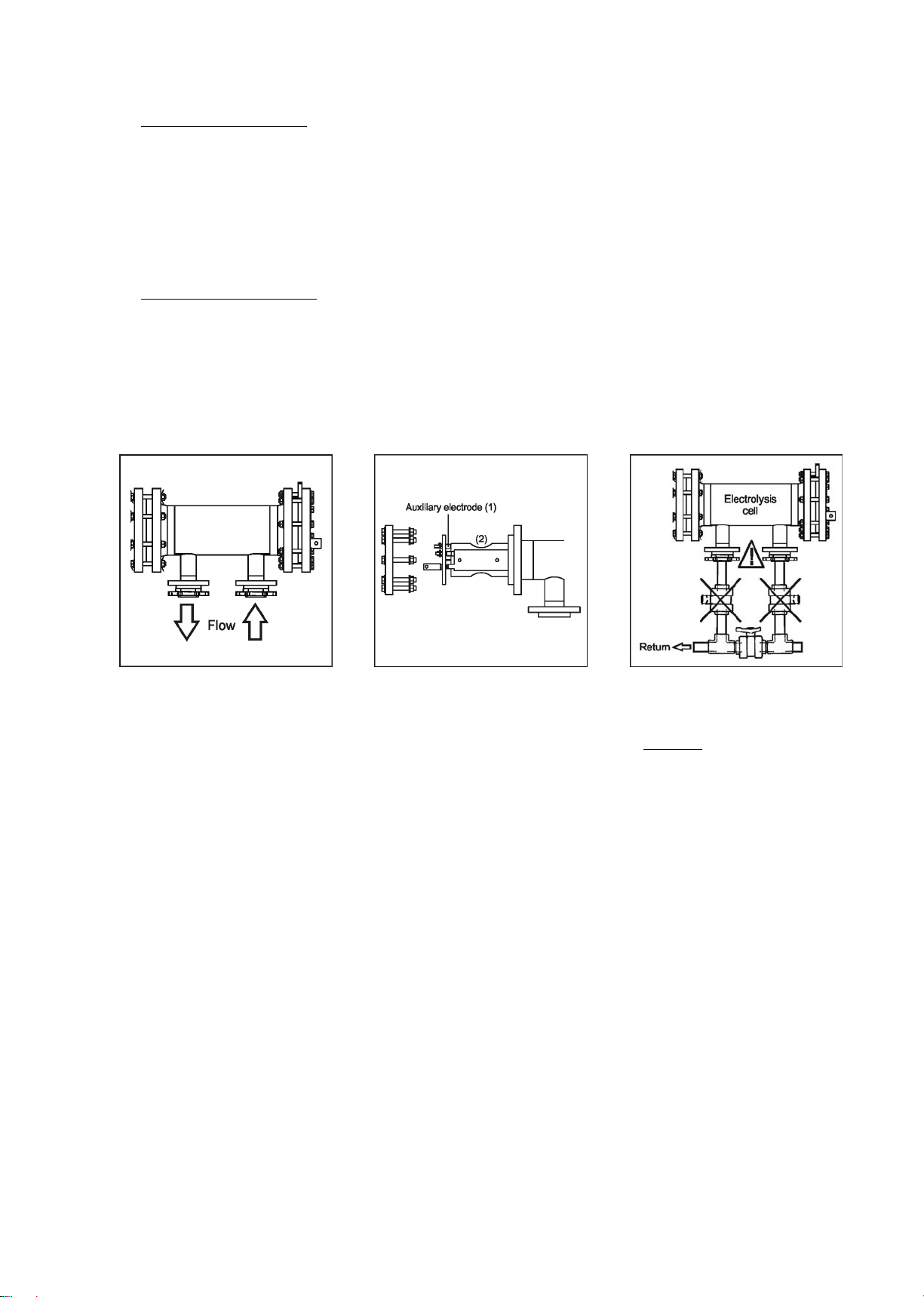
Fig. 3
Fig. 4
Fig. 5
1. Flow direction marked in the cell
must be respected. Recirculation
system must guarantee the minimum
flow stated in the Table of Technical
Specifications for each model (see
Section 9).
2. The system flow detector activates if
there is not recirculation (flow) of water
through the cell or if flow is very low. If
electrolysis gases are not properly
removed through the electrolysis cell,
the generated gas bubble electrically
isolates the auxiliary electrode
(electronic detection). Therefore, when
locating the electrodes in the cell, the
level sensor (auxiliary electrode) will
have to be located in the higher area of
the cell. The safest orientation is shown
in the recommended installation
diagram.
3. WARNING: if the in-out valves of the
electrolysis cell are closed
simultaneously, the flow detector (gas
detector) will not work correctly, with
the consequent risk of cell breakdown.
Although this situation is extremely
unusual, it can be easily avoided once
the equipment has been installed, by
locking at opened position the return
valve to the swimming pool, so it
cannot accidentally be manipulated.
6
4.3. Electrical connection of the electrolysis cell
Make the interconnection between the electrolysis cell and the power supply according to the following scheme. Due to relatively high current
intensity circulating do not modify or cut either the length or section of the supplied cables without making a previous consultation to an
authorized ASTRALPOOL distributor. The cable connecting the electrolysis cell and the power supply should never exceed the maximum
length recommended in the section 9 of this Manual:
ES-70/90
(all versions) ES-180
(all versions)
1.- Electrode 1 (Brown or Blue)
2.- Electrode 2 (Blue or Brown)
3.- Flow detector (Yellow)
Fig. 6
4.4. Installation of the pH / ORP sensors
1. Install the pH and ORP electrode holders in the circuit through ½” saddles (not included with the equipment) (Fig. 7).
2. Insert the electrodes into their corresponding holders. Next, tighten the holder until the electrode is properly fixed.
3. The electrodes must be installed in the holder so that it is guaranteed that the sensor located in their ends are always submerged in
the water circulating through the pipe.
4. Install always the electrodes vertically or with a maximum inclination of 40º. (Fig. 8).
5. Connect the pH / ORP sensor provided with the unit to the corresponding BNC connectors located in the unit’s side.
Fig. 7
7
Fig. 8
4.5. Installation of the external flow detector (optional, not supplied with the unit).
1. Install the saddle supplied in a section of the pipe at the entrance to the electrolysis cell. It should always be installed in a horizontal
position relative to the ground (see Fig. 9-1).
2. Install the flow detector (flow switch) vertically in the saddle (Fig. 9-1).
3. There is an arrow on the head of the flow detector. Make sure that this arrow is parallel to the pipe shaft and pointing in the direction
that the water flows (Fig. 9-2).
4. Do not install the flow detector near magnetic objects. They could affect the operation of the magnetic device it contains and reduce
its reliability.
Fig. 9-1 Fig. 9-2
4.6. Installation of the control terminal
In the EASY SALT systems it is possible to establish a remote control of the electrolysis salt system installed in the swimming pool by means of
a control wall terminal installation. The interconnection between the power supply and the control terminal can be executed through a 6-
conductor signal cable connected to the respective connectors in power and visualization cards. The cable length will be determined by the
customer’s requirements but must be always lower than 40 meters. The terminal is 10,5 Vac auto-supplied by the communication bus, so it
doesn’t need any additional supply.
The wall terminal doesn’t require any special maintenance procedure, with the exception of these maintenance recommendations:
oUse a slightly moisten cloth to clean it.
oDon’t use aggressive cleaning products (bleach, sprays, solvents, alcohol, etc.)
The control terminal is designed to be installed on a rigid wall. Its IP-65 degree allows the outdoor installation. Nevertheless, it’s recommended
not to expose the terminal to the solar rays. In order to install the remote control, follow the instructions shown below:
8
To install the control terminal, proceed as follows:
OPTION A: installation using the original ASTRALPOOL cable ref. ES-020-XX (XX indicates the cable length in meters).
OPTION B: installation using a standard 6-conductor signal cable (each conductor must have a 0,22 mm2minimum cross section).
In both cases the maximum possible length is 40 meters. Nevertheless, using an Unshielded Twisted Pair (UTP) (Category 5e unshielded)
allows interconnection distances until 60 meters.
1. For that purpose, disassemble the control terminal by removing the four fixation screws. Pass the new communication (A) through the
cable gland located at the base of the terminal and plug it into any of the two connectors of the control board labelled (CN1A CN2A)
[OPTION A], or in the CN-5 connector [OPTION B]. After this operation, reassemble the control terminal again.
Fig. 10
2. Pass the free end of the communication cable through one of the cable glands on the basis of the power supply and connect it to the
connector (CN10A, CN11A) [OPTION A], or to CN-20 connector [OPTION B] of the power board. Once this operation finished,
reassemble the chassis of the power supply.
Fig. 11
3. Fix the wall mounting kit (see section 8) at the selected point of installation and hang the terminal into it.
9
4.7. Controls and indicators
EASY SALT electrolysis systems are equipped with a control panel in the front (Figs. 12, 13).
Fig. 12. ES-XX+ models control panel.
Fig. 13. ES-XX+ models control panel.
1. Key “”(decrease production / programming menu
navigation).
2. Indicator of activated AUTOMATIC COVER control.
3. Indicator of activated ORP control (AUTO mode)
4. Production scale (%)
5. SALINITY TEST scale.
6. Indicator of LOW SALINITY.
7. Indicator of HIGH SALINITY.
8. SALINITY scale (qualitative).
9. Key for “SALINITY TEST”.
10. SELF-CLEANING indicators
(DIRECT / REVERSE) polarity.
11. Display of SYSTEM INFORMATION.
12. Indicator of FLOW ALARM.
13. Indicator of ELECTRODE passivation ALARM
14. Key “”(increase production / programming menu
navigation).
15. Display of water pH.
16. Indicator of HIGH PH ALARM (> 8.5).
17. Key for pH CALIBRATION MODE.
18. Indicator of PH SETPOINT.
19. Indicator of LOW PH ALARM (< 6.5).
20. Key for PH SETPOINT PROGRAMMING
21. Display of water ORP.
22. Indicator of HIGH ORP ALARM (> 850 mV)
23. Key for ORP CALIBRATION MODE
24. Indicator of ORP SETPOINT.
25. Indicator of LOW ORP ALARM (< 650 mV)
26. Key for ORP SETPOINT PROGRAMMING
10
Besides basic operations, the EASY SALT electrolysis system has three inputs for voltage-free contacts, enabling the connection of additional
external controls. They are located on connector [CN7] of the power card (Fig. 17).
Fig. 14
The logic associated to these three inputs can be programmed during the system configuration process (see section 5.2)
o[FS] OPTIONAL EXTERNAL FLOW DETECTOR CONTROL (not included with the equipment): input for potential-free contact.
When the contact connected to this input is open (external flow detector at rest), and the [FS] is configured as [FS1c], the
electrolysis system switches off due to the flow alarm. Connect the external flow detector wiring to the respective input [FS],
placed in the [CN7] connector, on the unit’s power card.
Fig. 15
o[co] AUTOMATIC COVER CONTROL: input for potential-free contact. Depending on the status of the contact connected to it
on the automatic cover’s electric panel, this input enables you to programme a reduction of the equipment’s output current to a
percentage of its nominal value.
Fig. 16
11
o[or] ORP / RESIDUAL CHLORINE control (EXT-1 models): input for potential-free contact. This input can be used to install an
external controller of the electrolysis system (ORP, RESIDUAL CHLORINE, PHOTOMETER, etc.). To that purpose connect two
cables from the potential-free contact, placed in the external controller, to the corresponding input [or] placed in the system’s
control card.
Fig. 17
4.8. Start-up
1. Check that the filter is 100% clean, and ensure that the swimming pool and the installation do not contain copper, iron or algae. Ensure that
any heating equipment on the pool is suitable for use in salt water.
2. Ensure that the swimming pool water is balanced, because like that the chlorine produced is used more efficiently and effectively, and
ensures that the life of the electrodes is prolonged. Water should be maintained within the parameters shown below.
a) pH must be in the range 7.2-7.6
b) Total alkalinity must be in the range 60-120 ppm
3. Although the EASY SALT system can operate within a salinity range of 4 – 6 g/l, the minimum recommended level of salt, 5 g/l, should be
maintained by adding 5 kg per m3of water if the water did not previously contain salt. Always use common salt (sodium chloride), without
additives like iodides, that is “apt for human consumption”. Never add the salt through the electrolysis cell. Add it directly to the swimming pool
or into the balance tank.
4. When adding the salt, and in case the swimming pool is going to be used immediately, carry out a treatment with chlorine. An initial dose of 2
g/m3of trichloroisocyanuric acid may be added.
5. Prior to starting up the salt chlorinator, disconnect the power supply to the salt chlorinator and run the pump for 24 hours to ensure that the
salt is completely dissolved.
6. Next, reconnect the power supply and turn on the salt chlorinator, locating the production level so that free chlorine concentration stays within
the recommended range (0.5 – 1.5 ppm).
NOTE: in order to establish the free chlorine level you will need to use a test kit.
7. In outdoor swimming pools it is advisable to maintain a level of 25-30 g/m3of chlorine stabiliser (cyanuric acid) in the pool. A level of 75 ppm
should be never exceeded. This will help to stop the chlorine that is in the water from being destroyed by the sun.
12
5. OPERATION: _____________________________________________________________________________________________________
5.1. System on stand-by
The system goes into “STAND-BY” when the “”[1] key is pressed until the “0%” light blinks. When this occurs, there is no production in the
electrolysis cell.
Fig. 18
5.2. System configuration
The EASY SALT system can be reconfigured through a menu accessed from the control panel. The system has to be switched off, as described
in point 5.1, in order to access this menu. Once the system has been switched off, press the “”[1] key for a few seconds until the system
information screen [11] displays “CONF”. To enable selection of each menu option, keep the “SALT TEST” [9] key pressed for approximately 1
second. Select the desired parameter using the “”[1] / “” [14] keys and validate by pressing the “SALT TEST” [9] key for one second again
(see Fig. 23). The configuration process enables you to establish the following operative parameters:
MODEL
Easy Salt 70
Easy Salt 90
Easy Salt 180
SOFTWARE VERSION
Shows software version (two digits)
POLARITY SWITCH
Switch every 2 hours (2)
OUTPUT LEVEL CONTROL
WHEN CLOSED COVER
(2)
System may be configured to provide an output to cell in the range 10 ... 90% of its nominal
capacity when the pool cover is closed.
COVER CONTROL INPUT ACTIVATION
Deactivated
Deactivated
Deactivated
ORP/RESIDUAL CHLORINE
CONTROL INPUT ACTIVATION
Deactivated (MANUAL) (2)
System activated when closed contact (AUTO)
GAS DETECTOR ACTIVATION
Deactivated
System activated when flooded detector (2)
EXTERNAL FLOW DETECTOR
(FLOW SWITCH) ACTIVATION
Deactivated (2)
System activated when closed contact
(1) WARNING: only use this mode for check tasks, for short periods of time, as it could damage the electrodes. This mode is cancelled when the system is switched off.
(2) Factory defaults.
Fig. 19
13
Fig. 20 System programming flow-sheet.
14
5.3. Production level selection
To select the desired production level, press the “”[1] / “” [14] keys until the production level light blinks. The system information screen
[11] will display the value of the production scale light [4]. The system will set its production to the desired level after a few seconds.
Fig. 21
In normal conditions, the production value [4] should be the same as the programmed value. However, if the salt level in the water is outside the
permitted range (“HIGH SALT” [7] or “LOW SALT” [6] alarms on), or there is a problem in the electrolysis cell (“ELECTRODES” [13] alarm on),
the production value [4] could be lower than the programmed and displayed value [11].
WINTER Mode:during periods of low water temperature select a production level [1] in the 50-60% range.
5.4. Salinity test
The EASY SALT systems have an integrated system to detect the salinity level of pool water. To run the test, press the “SALT TEST” [9] key.
During the test, the production light will range from 20%-80% of the salinity scale [5], alternately displaying “SALT” and “TEST” on the system
information screen [11]. Once the test is completed, the light will blink for a few seconds on the scale [5] on the detected salinity value (see Fig.
22). The equipment will return to normal operating mode after a few seconds. The system might show lower than actual salt levels if the
temperature falls beneath 20C (68 °F).
Fig. 22
15
5.5. Integrated pH controller
The integrated pH / ORP controller is supplied with a default factory calibration and programmed with the following parameters:
SETPOINT pH=”7.2” / ORP=”700 mV”
IMPORTANT: In order to have a correct regulation of the pH value, the Total Alkalinity of the pool water must be maintained in the range
60–120 ppm CaCO3. Use a pool water test kit to check the Total Alkalinity and adjust manually if necessary.
5.5.1. CONNECTION OF THE PH / ORP SENSORS
Connect the pH / ORP sensor provided with the unit to the corresponding BNC connectors located in the unit’s base (Fig. 23).
5.5.2. CONNECTION OF THE DOSAGE PUMP
The EASY SALT systems (ES-XX/EXT-1 models) have a connector on their base for connecting a dosage pump to control the pH of the water
in the pool. The dosage pump can be connected through the CEE22 connector supplied for that purpose with the equipment (Fig. 23).
Fig. 23
5.5.3. PH SETPOINT PROGRAMMING
Keep the “SET” [20] key pressed until the screen [18] displays the desired pH value within the 7.0 – 7.8 range. Release after selection.
Fig. 24
16
5.5.4. ORP SETPOINT PROGRAMMING
Keep the “SET” [26] key pressed until the light displays the desired ORP value within the 600 – 850 mV range. Release after
selection.
Fig. 25
5.5.5. SAFETY STOP CONFIGURATION OF THE DOSAGE PUMP (PUMP-STOP FUNCTION)
The integrated pH controller has a security system (PUMP-STOP FUNCTION) acting on the dosage pump which allows to avoid the following
situations:
Damages caused by the dry operation of pump (depleted pH-minus product).
Over-dosage of pH-minus product (damaged or aged sensor).
PH regulation problems due to high alkalinity in the water (newly filled pool, high carbonate levels).
When the PUMP-STOP FUNCTION is enabled (factory default), the system stops the dosage pump after a programmed time without having
reached the pH setpoint.
Fig. 26.
The PUMP-STOP FUNCTION is factory set to 60 minutes. To change this value, follow the next procedure.
17
Fig. 27.
5.6. Alarms
HIGH SALT LEVEL
If too much salt has been added, the production level will automatically fall beneath the selected level. The “HIGH SALT” [7] light will
stay on. In this case, empty part of the pool (10%, for instance) and add fresh water to reduce the salt concentration. To precisely
measure the salt level, we recommend the use of a portable salinity-temperature meter
LOW SALT LEVEL
If there is less than the recommended salt content in the pool, the selected output level cannot be reached. The “LOW SALT” [6] light
will stay on. In this case, measure the salt level in the water and add the required amount of salt. The common salt (NaCl) used for
electrolysis should not contain additives (anti-caking agents, iodine) and must be suitable for human consumption. The system may
indicate a low salt level if the temperature falls beneath 20°C (68 °F). To precisely measure the salt level, we recommend the use of a
portable salinity-temperature meter.
High salt level
Low salt level
Fig. 28
WATER LEVEL IN CELL/FLOW DETECTOR (GAS)
If an air or gas bubble forms at any time at the top of the electrolysis cell and the FLOW DETECTOR is not submerged, the system
will automatically switch off production, with the “FLOW” [12] light blinking and “FLO” displayed on the system information screen [11].
The system automatically resets when water flows through the cell again or the bubble disappears.
18
1. Submerged gas detector. System running. 2. Gas detected. Insufficient flow. System of
f
.
Fig. 29
OPTIONAL EXTERNAL FLOW DETECTOR / FLOW SWITCH (not included with the equipment)
During the system configuration process (point 5.2), the input for the external flow switch is activated (factory-programmed default
value), the system will automatically switch off production, with the “FLOW” [12] light blinking, and “FLO” displayed on the system
information screen [11]. The system automatically resets whenever water starts to flow through the flow switch again.
1.
A
ctivated flow detector (contact closed). System running. 2. Flow detector at rest (contact open). System of
f
.
Fig. 30
19
ELECTRODES
The EASY SALT system has a light indicating malfunction of the electrolysis cell electrodes [13]. This usually occurs at the end of the
electrodes ’useful life, when they lose their power. However, although this is a self-cleaning system, this malfunction could also be
due to excessive scaling on the electrodes when the system operates with hard water with a high pH value.
Fig. 31
PH / ORP OUT OF RANGE
The integrated pH/ORP control system has two ALARM lights which come on whenever a pH value of less than 6.5 “LOW” [19] or
more than 8.5 “HIGH” [16] is detected, or ORP falls outside the 600 mV “LOW” [25] - 850 mV “HIGH” [22] range. When the regulator
detects an active pH alarm, it opens the control output of the dosage pump (pH).

This manual suits for next models

9

Other Astral Pool Water Filtration System manuals

Astral Pool Combo 27413 Manual

Astral Pool

Astral Pool Combo 27413 Manual

Astral Pool XC Series User manual

Astral Pool

Astral Pool XC Series User manual

Astral Pool Combo 22440 Manual

Astral Pool

Astral Pool Combo 22440 Manual

Astral Pool VX - 3 Series User manual

Astral Pool

Astral Pool VX - 3 Series User manual

Astral Pool 11620 User manual

Astral Pool

Astral Pool 11620 User manual

Astral Pool 11405 User manual

Astral Pool

Astral Pool 11405 User manual

Astral Pool E Series User manual

Astral Pool

Astral Pool E Series User manual

Astral Pool Asralpool Chlore Smart 30 Manual

Astral Pool

Astral Pool Asralpool Chlore Smart 30 Manual

Astral Pool HydroSpin Compact Manual

Astral Pool

Astral Pool HydroSpin Compact Manual

Astral Pool APR-3 Series User manual

Astral Pool

Astral Pool APR-3 Series User manual

Astral Pool Viron V25 User manual

Astral Pool

Astral Pool Viron V25 User manual

Astral Pool SEL BLUE EVO User manual

Astral Pool

Astral Pool SEL BLUE EVO User manual

Astral Pool SEL BLUE User manual

Astral Pool

Astral Pool SEL BLUE User manual

Astral Pool SALT EXPERT-3 User manual

Astral Pool

Astral Pool SALT EXPERT-3 User manual

Popular Water Filtration System manuals by other brands

Clack WS CI Series Installation, operation, maintenance guide

Clack

Clack WS CI Series Installation, operation, maintenance guide

Berkey Blue Travel Berkey user manual

Berkey Blue

Berkey Blue Travel Berkey user manual

UV Dynamics UVD320/S Installation and maintenance manual

UV Dynamics

UV Dynamics UVD320/S Installation and maintenance manual

Aquasana EQ-400 owner's manual

Aquasana

Aquasana EQ-400 owner's manual

AC Infinity CLOUDLINE Series user manual

AC Infinity

AC Infinity CLOUDLINE Series user manual

Reverse Osmosis BlueClear-RO-50 Installation and user manual

Reverse Osmosis

Reverse Osmosis BlueClear-RO-50 Installation and user manual

ELTA music POLYVOX PF3 manual

ELTA music

ELTA music POLYVOX PF3 manual

Aqua Optima Clarion Instructions for use

Aqua Optima

Aqua Optima Clarion Instructions for use

HOME WATER EZ CHANGE manual

HOME WATER

HOME WATER EZ CHANGE manual

BSV BSPOOL PRO200 user manual

BSV

BSV BSPOOL PRO200 user manual

Adey MagnaCleanse user guide

Adey

Adey MagnaCleanse user guide

flamco MeiFlow Shunt UD DN15 S Installation & service instructions

flamco

flamco MeiFlow Shunt UD DN15 S Installation & service instructions

Levoit True HEPA LV-H133-RF instructions

Levoit

Levoit True HEPA LV-H133-RF instructions

Sterilight S1Q-DWS Installation instructions & owner's manual

Sterilight

Sterilight S1Q-DWS Installation instructions & owner's manual

JRC NSVS1154 manual

JRC

JRC NSVS1154 manual

Insignia NS-4396508-2 Quick setup guide

Insignia

Insignia NS-4396508-2 Quick setup guide

Beko DRYPOINT M PLUS Instructions for installation and operation

Beko

Beko DRYPOINT M PLUS Instructions for installation and operation

EHEIM reeflex UV 350 operating instructions

EHEIM

EHEIM reeflex UV 350 operating instructions

manuals.online logo
manuals.online logoBrands
  • About & Mission
  • Contact us
  • Privacy Policy
  • Terms and Conditions

Copyright 2025 Manuals.Online. All Rights Reserved.