ASTRO-PHYSICS Mach2GTO User manual

Astro-Physics, Inc.
11250 Forest Hills Road
Machesney Park, IL 61115
Telephone: 815-282-1513
www.astro-physics.com
July 2020
Keypad Optional

1
ABOUT THIS MANUAL 3
MACH2GTO PARTS LIST 4
MECHANICAL FEATURES AND SPECIFICATIONS 5
INTRODUCTION 6
Why Polar Alignment is Important 6
Key Points Unique to the Mach2GTO 7
UNDERSTANDING YOUR MACH2GTO 8
RA and Dec Clutch Knobs 8
Hard Stops and Clutches in the Mach2GTO 9
Gear Mesh 9
GTOCP5 Control System 10
Periodic Error Memory (PEM) Correction 10
About Absolute Encoders on the Mach2GTO 11
Never Needs Homing. Simply Polar Align; Power Up; and GO!! 11
How to Recover from a Recalibration Error 11
Mach2GTO Encoders Compared with Other Mounts 11
Benets of Absolute Encoders Summary 12
Separate Your Mount for Travel, Reduced Weight or Semi-Permanent Setups 13
NOW IT’S TIME TO SET UP! 14
Additional Handy Tools 14
Assemble Pier, Tripod or Flat Surface Adapter 14
6” Eagle Folding Pier (EAGLE6-EZ) 14
Berlebach Wood Tripod (AWTBER2) 15
Losmandy Light-Weight Tripod (LMLWT-AP) 15
Tripod Adapter (ADATRI) 15
Attach the Mount to the Pier or Tripod 16
Attach GTOCP5 Control Box 17
Attach Pier Trays, if Any 17
Attach Counterweight Shaft 18
Consider Rough Polar Alignment at this Point 18
Attach Counterweights 18
Counterweight and Inertial Moment Arm Considerations 18
Attach Mounting Plate 19
Attach Telescope 19
CABLE CONNECTION 20
Connecting RA and Dec Cables to the Mount 20
Connecting Accessories to Internal Cabling 20
LET’S TALK CABLES 21
ASTRO-PHYSICS
Mach2GTO GERMaN EQUaTORIaL wITh
GTOCP5 Micro-Step Servo System

2
Computer to GTOCP5 21
Computer to Internal Cable Link 21
Connecting Computer to Mount Internal Input 22
Using USB 3.0 Active Cable and Gender Changer 22
Using USB 3.0 Active Cable to Powered Hub and Data Transfer Cable 22
Connecting Mount Internal Output to Communication/Power Hubs 22
Using Pegasus Astro “Ultimate Powerbox V2” and “Pocket Powerbox Advance” 22
Using USB 3.0 Communication Hub and RIGRunner Power Distribution 22
Using Primaluce Lab Eagle3 Communication Hub and Power Distribution 22
BALANCING THE TELESCOPE 23
Cable Considerations 23
POLAR ALIGNMENT – THE FUNDAMENTALS 24
Azimuth Adjustments 24
Altitude Adjustments 25
POLAR ALIGNMENT – THE REFINEMENT 27
Methods for Fine Polar Alignment 27
Altitude and Azimuth Adjustments 28
Fine Altitude Adjustment 28
Fine Azimuth Adjustment 29
Tweaking Your Alignment 30
Mach2GTO Daytime Polar Alignment Method 30
Using Software to Improve Pointing Accuracy 30
QUICK START SUMMARY – FIRST SESSION WITH YOUR KEYPAD 31
QUICK START SUMMARY – FIRST SESSION WITH YOUR COMPUTER 32
AT THE END OF YOUR SESSION 33
REMEMBER THESE TIPS 34
MOUNT CARE, CLEANING AND MAINTENANCE 35
Care 35
Cleaning and Touch-up 35
Counterweight Appearance 35
Worm Wheel Maintenance 35
Greasing Mount 35
TROUBLESHOOTING AND SUPPORT 36
Troubleshooting and Tips 36
Additional Support 37
APPENDIX A: PRE-DEFINED PARK POSITIONS 38
APPENDIX B: DRIFT ALIGNMENT – RA CORRECTION METHOD 40
APPENDIX C: ROLAND’S GTO QUICK STAR DRIFT METHOD - 2020 VERSION 41
APPENDIX D: POSITION FOR SHIPPING AND COMPACT STORAGE 42
APPENDIX E: MOUNTING PLATE FASTENER CHART 43
APPENDIX F: MOUNTING PLATE OPTIONS 44

3
ABOUT THIS MANUAL
This version of the Mach2GTO Manual was prepared for the production run of mounts (serial # M20011 and later) that
began shipping in February of 2020. Most of the information in this manual is applicable to all Mach2GTOs that have
been produced. We have also learned a few things through experience and the suggestions of our customers that have
improved the information available in this manual.
You should note that this manual is actually one component of a three-document system.
●Mach2GTO German Equatorial Mount manual
●GTO Micro-step Servo System manual
●Keypad manual (only shipped with optional Keypad order)
This Mach2GTO Manual will cover the Mach2GTO’s mechanical features and physical operations.
We highly recommend the Support section of our website for the latest information and for future updated versions of this
manual. There are also valuable information and help guides.
A nal note and an apology to our friends in the southern hemisphere. Many of the instructions in this manual are written
entirely from the point of view of those of us in the northern hemisphere. Since descriptive terms like left and right are
meaningless without a dened point of reference, we tend to use east and west to avoid ambiguity. The east and west
sides of a German equatorial mount are, of course, reversed in the southern hemisphere. At one point, our thought was to
always use phrases like the following: “...on the east side (west side in the southern hemisphere)...” This quickly became
cumbersome and made the text more difcult to read. For simplicity, we decided to leave many of the explanations in their
northern hemisphere framework. Thank you for your understanding.
Note: Some photos may differ slightly from the current mounts that are shipping.
Please RecoRd the Following inFoRmation FoR FutuRe ReFeRence
Mount Serial Number: _____________________________________________
GTOCP5 Serial Number: _____________________________________________
Keypad Serial Number: _____________________________________________
Purchase Date: _____________________________________________
User Name and Password: _____________________________________________

4
MACH2GTO PARTS LIST
1 Mach2GTO German Equatorial Head with Micro-step Servo System
1 GTO Control Box (model GTOCP5) with control box-to-pier adapter (CBAPT)
1 13.7” x 1.875” Stainless Counterweight Shaft (M2043) with Delrin Washer and Machined Safety Stop (M12676)
1 24 volt power supply (PS24V10AP)
1 D.C. power cord set - 6’ cable with Powerpole connectors (CABPP6) and clip (FPCLIP)
1 1/4-20 Machined Knob Kit (M1485KBKIT)
1 15’ serial cable (CABSER15)
1 USB Flash Drive containing PDF of Instruction Manuals
1 Hex key set
Instruction Manuals and Registration Card
All required fasteners
In order to fully use your mount, you will need some of the following items sold separately. Many of
these items will be discussed throughout these instructions.
●Dovetail saddle plate: There are several choices to t your telescope and observing needs. See detailed
information in “APPENDIX F: MOUNTING Plate Options” on page 44
○10” Dual-style Dovetail Saddle (DOVEDV10) – recommended for most scopes used with this mount.
○16” D-style Dovetail Saddle (DOVELM162) – recommended for large scopes
●Pier or Tripod:
○6” Eagle Folding Pier (EAGLE6-EZ)
○Berlebach Wood Tripod (AWTBER2) – requires Extension for Control Box Adapter (Q6280KIT)
○Losmandy Light-weight Tripod for AP (LMLWT-AP) – ideal for portability when travelling
○Adapt to your own custom pier or tripod with our Tripod Adapter (ADATRI)
●Counterweights: 5 lb. (5SCWT), 10 lb. (10SCWT) and 18 lb. (18SCWT) counterweights are available for the
standard 1.875” diameter counterweight shaft. Generally, 85-125% of the weight of the scope, mounting plates and
accessories is required in counterweights (more weight is required with larger diameter SCT scopes).
Several additional options are available. Many of these items will be discussed throughout these
instructions:
●Optional Keypad Controller with 15’ Coiled Cable: Hand-held computer to operate the mount without a PC and
additional software.
●Right-Angle Polar Alignment Scope with LED Illuminator (RAPAS) and Adapter (RAPM2): for quick and easy
polar alignment. Adapter and polar scope attach externally to the Mach2GTO.
●Pier Accessory Trays: A at accessory tray with raised sides (TRAY06), a tray with eyepiece holes (TRAY06H), and
two support bar options (TRAYSB or TRAYSB1) are now available to t the 6” Eagle Adjustable Folding Pier and both
tripods. They are handy places to keep your eyepieces and astro-gadgets close at hand! They can also be used with
the 8” Eagle Extension (EAGLE6E8) on other tripods. An extension is required for attaching trays to a Berlebach or
Losmandy tripod
●Autoguiding Accessories: Our 10 x 60 Vario-Finder with Guider Bracket Kit (1060VGKIT) is a highly recommended
accessory for imagers. The GTOCP5 Control Box takes advantage of timed pulse guiding commands offered by
most software guiding programs for best precision. See the GTOCP5 Micro-Step Servo System manual for more
information.
Additionally, various imaging and CCD-based guiding congurations can take advantage of the Mach2GTO’s
autoguider port (RJ-11-6) which uses the industry standard SBIG ST-4 wiring setup.
●Alligator Clips with APC Fuse to Powerpole Connector (CABPPAL): This adapter is used when powering the
mount from a battery (deep-cycle or Lithium Ion recommended) in the eld. The alligator clips attach directly to the
battery terminals.
●USB 3.0 A Male-to-A Male Cable: SNANSHI USB 3.0 A Male-to-A Male Cable, Comprehensive USB 3.0 A Male-To-
A Male Cable or Rosewill USB 3.0 A Male-to-A Male Cable are examples of quality cables.
●Pelican iM2875 Storm Travel case: Case can utilize the shipping foam with slight modication.

5
MECHANICAL FEATURES AND SPECIFICATIONS
Construction All parts CNC machined aluminum, stainless steel & brass bar stock; stain-
less steel fasteners
Worm wheels - RA/ Dec 5.9” (150 mm), 225 tooth aluminum
Worm gears - RA/ Dec 0.71” (17.9 mm) diameter, brass
Axis shafts - RA/ Dec 1.77” (45 mm) diameter
Periodic error 0.25 arcseconds peak-to-peak, 0.05 RMS
Motors Brushless micro-step servo system
AC-DC Power supply 24-volt, 10 amps continuous, universal 85-240V
Power requirements
Nominal 12 to 24-volt DC supply, minimum 5 amps continuous
12 Volts: Tracking - 1.5 amps DC, Max slewing rate @ 1200x (both axes) -
4.2 amps DC (50 watts)
24 Volts: Tracking - 0.8 amps DC, Max slewing rate @ 1800x (both axes) -
3.6 amps DC (86 watts)
Slew speed (maximum) 1200x with 12 volts (5 degrees/second)
1800x with 24 volts (7.5 degrees/second)
Latitude range 0-68 degrees, engraved scale
Azimuth adjustment Approximately 13 degrees (+ / - 6.5 degrees from center)
Counterweight shaft Dimension: 1.875” (47.6 mm) diameter x 13.625” (346 mm) usable length
Weight: 10.9 lb (4.9 kg) Light-weight scopes might not need counterweights
Weight of mount Total: 42 lb (19.8 kg)
Imaging capacity of mount 75 lb (34 kg), scope & accessories only, (maximum capacity depends on
scope diameter & length) See chart below.
Instrument mounting interface Refer to “Attach Mounting Plate” on page 19.
Diameter of base 5.80” (147.3 mm) (portion that is inserted into pier top or ADATRI adapter)
The capacity graph
above deals primarily
with effects on the RA
axis. RA must hold
both the instrument
and the
counterweights.
Declination has its
own considerations
WHY WEIGHT CAPACITY ALONE IS
AN INADEQUATE SPECIFICATION
Don’t mess
with Karen!
Go ahead!
Try this at home!
Inertial moment in Declination is a
function of instrument weight and length.
Dec. moment affects your ability to guide.
456 7 8 9 10 11 12 13 14 15 16 17 18 19 20
35
40
45
50
55
60
65
70
75
80
How to
Measure
OTA Tube Diameter or Overall Height
Weight in Pounds
SAFE
NOT RECOMMENDED!
NEAIC/NEAF
SETUP
Mach2 Capacity

6
INTRODUCTION
The Astro-Physics Mach2GTO –Observatory Performance in a Small Package! This is a highly-advanced, compact
and lightweight mount that was designed for utmost portability while maintaining extreme rigidity and superb tracking
accuracy. No shortcuts were taken to achieve these goals. The integrated absolute encoders, the use of precision
machine tool bearings and the innovative worm wheel / clutch design represent a new approach to the overall performance
of this mount.
The advent of modern CCD cameras and telescopes with high-resolution optics has placed greater demands on the ability
of mounts to do their part to achieve precision tracking and guiding. At the same time, the mount should be easy to use
with adjustments and setups that are straightforward and accurate. We have done everything possible to eliminate the
frustrations and limitations inherent in a lesser mount and to put the fun back into the hobby of amateur astronomy.
The Mach2GTO employs the reliable and sophisticated Astro-Physics GTOCP5 Micro-Step Servo System. The system
uses precise micro-step motors that are controlled with absolute encoders by the remarkable GTOCP5 control box. The
GTOCP5 is truly the brains of the system taking your wishes as expressed through a command input device like the Astro-
Physics Keypad or a computer, and translating them into actions taken by the mount.
The advanced features of the optional keypad allow you to slew automatically to objects in a wide range of databases, as
well as any RA/ Dec coordinates. A large selection of common star names and non-stellar objects makes your selection a
snap. Version 5.x also includes an orthogonality routine and pointing model. Keypad operation is simple and intuitive.
Various computer software and our fully supported V2 ASCOM driver are available to make the connection between you,
the astronomer, and the servo system versatile and straightforward. Details on the servo system and the various options
for control software can be found in the separate Astro-Physics GTOCP5 manual.
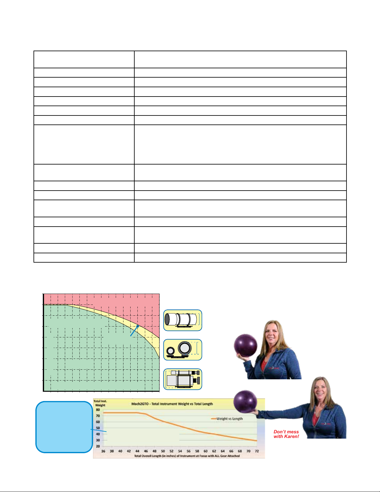
The Mach2GTO has the strength, rigidity and sophistication to tempt you to permanently place it in a state-of-the-art
observatory. However, its portability and ease of setup make it the nest mount of its size for remote use in your favorite
dark sky site and even for travel to exotic observing locations around the world. This is the perfect mount for a small to
mid-size refractor, Newtonian, Cassegrain or astrograph. Whether you enjoy visual astronomy exclusively or plan an
aggressive astro-imaging program, this mount will allow you to maximize your night out under the stars.
In order to fully enjoy your rst night out, we recommend
that you familiarize yourself with the assembly and basic
operation of the mount indoors. The temperature will be
comfortable, the mosquitoes at bay, and you’ll have enough
light to see the illustrations and read the manuals. Please
take particular note of balancing, use of the clutches and
operation of the keypad controller.
We offer Quick Start Summaries in this manual and more
information in the GTOCP5 manual to assist you with keypad
and computer operation.
Why Polar Alignment is Important
Polar alignment is required in order to compensate for
the Earth’s rotation. If you were to take a long exposure
photograph while aimed at the celestial pole, you would
discover that all stars seem to revolve around it. This effect
is due to the rotation of the earth on its axis. Motor driven
equatorial mounts were designed to compensate for the
earth’s rotation by moving the telescope at the same rate,
though opposite to the earth’s rotation. When the polar axis
of the telescope is pointed at the celestial pole (polar aligned)
as shown in the diagram, the mount will follow (track) the
motions of the stars, planets and deep sky objects. As
a result, the object that you are observing will appear
motionless as you observe through the eyepiece or take
astrophotos.
Equator
South North
Direction of
the Celestial
North Pole
Earth
Direction of
the Celestial
North Pole
Direction of
the Polar Axis
Horizon
Zenith
Earth’s Axis
L
a
t
i
t
u
d
e
L
a
t
i
t
u
d
e
Northern
Hemisphere
Earth’s Rotation
Mount’s
Counter-rotation

7
Key Points Unique to the Mach2GTO
●The GTOCP5 Control Box is individually paired to the mount. It cannot be swapped to any other
mount; not even another Mach2GTO. Note that the serial number of the GTOCP5 is the same as the
serial number of the mount. That is because the GTOCP5 contains the information necessary for the
perfect pairing of the worm and worm wheel with the absolute encoders.
●The Mach2GTO has integrated absolute encoders as mentioned above. These encoders eliminate all
RA periodic error and Dec backlash, in addition to providing absolute positioning. PEMPro is not needed
with the Mach2GTO, nor do you want to attempt to run periodic error curves.
●There is no need to resume from reference park positions with the Mach2GTO. It always knows
where it is! Just power up the mount and go to your rst object. Though not necessary, it is often
convenient to park at Park 2, Park 3 or Park 5 positions for reasons discussed later in this manual.
●You can trick the Mach2GTO, but a trip to Home will x it. Telling the mount to recalibrate on Deneb
when it is really Vega will cause incorrect orientation. However, just send it to Home and all will be perfect
again...ready for the next object. It is always best to know your objects before doing a ReCal.
NOTE: The compass shown below has been replaced by a lanyard post to hang the strap of your optional
Keypad.
Dec. Motor Box
R.A. Motor Box
Clutch Knobs (8)
Azimuth Adjuster
Altitude
Adjuster
Grease Port
Grease Port
RAPAS
Adapter (optional)
Altitude Locking
Knob (2)
USB & 12 Volt
Aux Out
USB & 12 Volt
Aux In
Tommy
Bar
Level
Opening
for
PoleMaster
Attachment

8
UNDERSTANDING YOUR MACH2GTO
Your new Mach2GTO Universal Robotic mount sets a new standard for portable telescope mounts. It is so easy to use that
you will be up and running in no time at all and the mount will simply disappear into the background. No fuss, no bother.
This section will introduce you to some features and fundamentals that will enable you to set up and use your mount
quickly.
Universal Robotic means that Mach2 fullls all of the requirements of a robotic mount for automated operation for imaging,
satellite tracking, comet tracking, star survey work and others. In addition, the clutches allow it to be used manually for
star sweeping. It is so easy to use that it can be set up quickly in the eld with minimal effort and no complicated startup
routines. The encoders keep track of the axis positions at all times whether parked, unparked, power on or power off.
RA and Dec Clutch Knobs
WARNINGS!
●Be careful when moving the mount with the clutches. A severely out-of-balance scope may make an unexpected and
perilous swing.
●Before carrying or transporting your mount, be sure all clutch knobs are locked to prevent an axis rotation and weight
shift in your hands.
You can balance the Mach2 nicely with the clutches. The motion is smooth and accurate and quite sensitive. Simply
loosen the clutches, swing the scope around to any part of the sky, tighten the clutches and the mount has kept track of
where you went, down to the arcsecond. No need to sync or recalibrate (ReCal) on a star when you have nished moving
the scope manually.
What do they do?
The four RA and four Dec clutch knobs have the function of connecting the RA
and Dec axes to their respective drive worm wheel gears. Their function is
progressive, from light tension (axes free to move – as required during correct
balancing of the telescope) to a completely locked state. Please note that the
clutches have no bearing whatsoever on the worm drive itself. They are simply
the mechanism that marries the worm wheel to the axis. The worm gears are
never taken out of mesh when the clutches are loosened.
As shipped, all Mach2GTO mounts have all four RA and Dec clutch knobs
rmly hand tightened. This will give you a good idea of the maximum tightness
(clutch action) that can be achieved by hand effort alone. Normally all four
clutch knobs on each axis (RA or Dec) should be tightened evenly with the
same tension. The clutches can be set by hand for light telescope loads, or the
can be fully tightened with an Allen key for heavier loads. You can temporarily
tighten just one knob during balancing; it is not necessary to always have equal
tension during such operations.
When properly balanced, you can move the scope around the sky manually
with clutches loose, or slightly tensioned, for sweeping the Milky Way or looking
for deep sky objects with your telescope. The mount will keep track of where
you are pointed and will resume tracking when you stop moving the scope. The
mount will always know where you are pointing, even with fully loosened clutches.
How tight can the clutch be and can you do any damage by over-tightening them?
These clutches can be tightened as much as needed. There is no danger of over-tightening. You will see that each clutch
knob has a 3/16” hex socket for tightening with an Allen key. Using the provided hex key, you can lock up the clutches so
that only the worm drives are able to move each axis. Fully locking the clutches only requires snugging the knobs with the
hex key...remember, the knobs are not the lug nuts of your car tire!
You should NOT attempt to push your scope by hand against a fully locked clutch, or undue stress will be placed on the
worm wheel, worm gear, and bearings. Also note that locked clutches provide no safety factor for your equipment should it
hit the pier!
Most users will never need to use a hex key on their Mach2GTO’s clutches. However, if you are heavily loaded, if your
system is out of balance, or if you are doing critical long exposure astrophotography, you may wish to have the extra clutch

9
tightness. As a general rule, if you have a big scope (6” refractor or 10” SCT) with all the accessories, you will need more
clutch tension than a 4” or 5” scope.
Hard Stops and Clutches in the Mach2GTO
The Mach2GTO has internal wiring that cannot be allowed to go more than 1 rotation of the axes. The hard stops prevent
cord wrap and possible damage to the internal cables. The axis shafts have two pins that stop rotation beyond 360
degrees.
The stops allow the RA axis to start up to 6 hours before the normal counterweight-up position in the east and up
to 5 hours past the normal meridian ip point in the west. Under normal operation with the telescope up and the
counterweights down, you will never encounter the hard stops. If you wish to image past the meridian, the stops will
engage after 5 hours of tracking and stop the motion of the axes. The motors will turn off automatically when the mount
is either slewed or tracked into the hard stops. You can also prevent slewing or tracking to these extremes by setting the
mount limits in the Keypad setup routine or in the APCC-Pro software. Refer to the appropriate manuals for guidance on
these features.
WARNING: The stops can be damaged if you allow a very heavy and severely unbalanced telescope load to
swing into the stop with the clutches loosened. The best way to avoid this is to never load a telescope onto
the mount without rst attaching all the counterweights to the counterweight shaft. Removing counterweights
before removing a telescope load can result in the RA axis and scope load swinging wild with possible damage
to the scope, yourself, and possibly the hard stop pin. Even without a telescope load the RA axis can swing
wildly if you have all 4 clutch knobs completely loose. It can then swing clockwise into the RA stop due to the
unbalanced weight of the Dec axis. Therefore, it is advisable to keep some tension on the clutch knobs during
setup. There is no harm to turn the axes with some clutch friction applied. Fully locked clutches cannot be
turned and should never be forced to turn manually.
Gear Mesh
The Mach2GTO has an advanced gearbox that maintains full contact of the gear teeth between the worm gear and worm
wheel. The teeth are always in contact, even when the clutches are fully loosened. They cannot slip or be damaged
because they are never separated.
The gearbox contains the motor, belt and pulley gear reduction
system, all of which is fully protected from damage by a set of
aluminum covers. The covers can be removed to inspect the belts
and wire harness. The belts are high strength premium timing
belts made for long life under extreme conditions. There are no
adjustments needed to any of these components under normal use.
It is not necessary to remove the gearbox in order to re-grease the
worm teeth. This can be done by removing a small cover on the side
of the gear enclosure which exposes a small section of the worm
teeth for cleaning and regreasing. Refer to “Greasing Mount” on page
35 for more information.

10
GTOCP5 Control System
We have developed a new control system which combines the precision performance of the Renishaw Resolute Absolute
Encoder with the whisper-quiet motion of brushless micro-step servo motors to produce a very accurate observatory-grade
mount that can also be set up in just a few minutes in the eld. The mount can be operated manually via the clutches or
electronically with the encoder loop providing the pointing and tracking functions.
● Each GTOCP5 control box is matched to its Mach2GTO and has been programmed specically for that mount. It
cannot be interchanged with another mount. Note that the serial numbers match so that you can ensure they remain
paired.
● The Mach2GTO uses a simple belt-drive micro-stepper motor in a closed servo-loop conguration.
●A rapid feed-forward servo loop stiffens the axes against outside disturbances such as cable drag and wind loading.
●Both axes can be run at custom tracking rates from sub-arcsecond motions per hour to 1000x sidereal.
●The GTOCP5 brushless servo system can be run from 12 volts with max slewing of 1200X (5 deg/sec) to 24 volts with
max slewing of 1800X (7.5 deg/sec).
●The power to the motors is self-limiting and cannot cause any kind of damage to the windings or the electronics, even
when in a stalled state.
●Integration of dual-axis absolute encoders ensure optimum performance.
●Multiple input options including: Ethernet, USB, RS-232 serial ports, and Keypad.
For detailed information regarding the function and operation of the GTOCP5, refer to the GTOCP5 manual that was
included with your mount and can be found on the Support web page.
Periodic Error Memory (PEM) Correction
The periodic error (PE) will be fully corrected when your mount is programmed by using input from the absolute encoders.
DO NOT attempt to use programs like PEMPro thinking that you need to correct periodic error. The next section will
discuss the role of the absolute encoders to provide near perfect PE.

11
About Absolute Encoders on the Mach2GTO
Mach2 Tracking Performance with Absolute Encoders - PE = 0.21 arcseconds
Never Needs Homing. Simply Polar Align; Power Up; and GO!!
An absolute encoder never needs to be homed to start your session. It is always home the minute power is applied. It
always knows where it is and transmits the exact shaft position to the control box at all times.
The encoders on the Mach2 are mounted on the axis shafts which move when the clutches are loose, and therefore the
encoders will read the position of the scope whether the clutch is loose or fully tightened. This is in contrast with our
1100GTO and 1600GTO mounts where the optional absolute encoders are part of the worm wheel. Since that wheel never
moves manually when the clutches are released, those mounts will not keep track of manual movements with clutches
loose.
Absolute encoders are always engaged when you power your mount to provide the highest performance . There is no
reason to turn them off.
How to Recover from a Recalibration Error
Your Mach2GTO always knows its position and can easily recover if you make a mistake by recalibrating on an incorrect
object. Although your mount may not point correctly to the RA or Dec coordinate that you specied, it is not lost. The
absolute encoders know exactly where they are. You can quickly recover by using the Home function in the Keypad or
Find Home in APCC. Follow the instructions provided in the appropriate manual.
Mach2GTO Encoders Compared with Other Mounts
Mach2GTO Encoders Compared with Other AP Mounts
All of our 1100GTO and 1600GTO mounts with Absolute Encoders have always used the Renishaw Resolute Absolute
Encoders for precise positioning and tracking. Now our newest mounts, the Mach2GTO, also have Renishaw Resolute
Encoders. What are the main differences between the Renishaw and other less expensive relative encoders?
Renishaw Gold Standard Accuracy!
Renishaw encoder accuracy is tested and veried against a laboratory standard. Each ring comes certied with its own
calibration measurement. The guaranteed maximum error on these rings translates to less than 1/2 arcsecond per hour
tracking error.
The Renishaw Resolute read-head interpolates a special barcode that is engraved on the matching stainless steel ring into
67 million individual addresses. Every address is unique and fully reproducible down to sub-arcsecond levels. This is not
possible with any relative encoder system.
Dependability to Astro-Physics Standards!
We have used Renishaw encoders for many years on our larger mounts, both in portable setups and in observatory remote
installations and have found them to be totally reliable. Renishaw encoders are also considered to be the gold standard

12
in the machine tool and robotics industries where precision is required. Yes, they are much more expensive than a simple
relative encoder, but for the type of accuracy required in a telescope mount, there is nothing out there that comes close.
We know, we have been evaluating options for years.
Absolute vs. Relative Encoders
Relative encoders use a simple ring that has engraved marks with separations on the order of 60 to 100 arcseconds
between ticks. In order to achieve sub-arcsecond resolution, the gaps between these marks are lled in electronically by a
method known as interpolation. Even the best interpolation methods have errors on the order of 5% (3 to 5 arcseconds).
When used in a telescope drive system these relative encoders introduce a fast-moving ripple in the RA tracking rate of 3
to 5 arcseconds, although the average or RMS value of this error can be quite low.
These peak excursions cause stars to move slightly back-and-forth in the RA direction during sidereal tracking. This
tracking ripple can remain hidden when imaging with short wide-eld scopes, but will manifest itself when using long-focus
instruments for high-resolution work. It is generally a fast-moving error, so it cannot be guided out.
Because of the ever present interpolation error (Sub-divisional Error, a.k.a. SDE) characteristic of lower cost relative
encoders, we decided long ago that we would not use them for tracking. Renishaw absolute encoders use a different type
of interpolation system that smooths out the SDE to a level that is not detectable. There is no mechanism for a relative
encoder to remove the SDE.
Benets of Absolute Encoders Summary
The utility of absolute encoders varies from brand to brand. Some manufacturers make very limited use of encoders and
use relative (not absolute) encoders to provide a potential benet to tracking and nothing else. The benets inherent to the
Mach2GTO with its premium dual on-axis absolute encoders include:
●The mount always knows where it is pointed regardless of power loss, movement of the axes when the power is off,
bumping the mount or wind movement.
●Homing positions can be set to whatever orientation a user wants, without limitation.
●No re-homing is required for remote locations should there be a power loss.
●Periodic error is fully corrected. No need for occasional PE measurement curves.
●Zero backlash in both axes for precision guiding.
●Dual-axis absolute encoders allow for variable tracking that automatically adjusts for refraction parameters.
● Very accurate pointing makes it easy to nd very faint objects.
●Very precise tracking such that unguided imaging may be accomplished with an appropriate optical/imaging setup.
●Very precise guiding, if needed, with instant response in both axes. Guiding is only needed to correct for optical/
imaging train issues, not mount issues.
●The dual-axis encoders enable the mount axes to accurately respond to your guider software commands down to the
1/10 arc sec level. There is no periodic error to ght; there is no Dec backlash delay to overcome.
● Corrects for polar misalignment and repeatable mechanical exure.
●Very precise dual-axis tracking is very important for high-precision tracking on objects like comets, asteroids, and
articial satellites, where the mount uses a “self-guiding” function based on orbital elements.
●Although absolute encoders cannot anticipate wind, they can react to it after the fact. So, you will have excursions but
the axis being affected will recover much faster when the encoders are on. The best strategy is to set your mount low
to the ground without extending the tripod legs. Large telescope tubes catch more wind then skinny ones. Same with
short scopes versus long ones.

13
Separate Your Mount for Travel, Reduced Weight or Semi-Permanent
Setups
Due to design restrictions related to the integrated, permanent internal cabling, it was necessary to create the Mach2GTO
mount without our usual RA and Dec separation. We have provided “Caution: Do Not Separate Axes” labels on the mount
to remind you so that you don’t inadvertently damage the cables if you forget. Please do not remove the warning labels
provided.
Although the Mach2GTO is a small mount and should not be a problem to setup by most users, there may be occasions or
circumstances where you want to separate your mount into smaller, lighter components. These may include airline travel,
permanent backyard piers, or just the desire to carry less weight. In these situations, the base can be easily separated
from the rest of the mount.
●This reduces the weight that you have to lift by 11 lbs, so your heaviest component is only 31 lbs.
●You can leave the base on your tripod when you move it indoors so you are ready for action the next time you go out.
●You can leave your pier with the base outside, polar-aligned and covered in a tarp; ready to go for your next observing
session.
● You may t the two pieces into your luggage for transport.
The procedure is simple. Use sensible caution.
1. If you have been using your mount, remove all instruments, counterweights, mounting plates and counterweight shaft.
2. Tighten all clutch knobs so that the RA and Dec axes do not move suddenly and freely.
3. If not attached to a pier, lay the mount on a thick bath towel or other soft padding so that the mount is not scratched.
You do not want the RA and Dec axes to tumble from the base when the screws are removed.
4. Three socket head screws on each side of the base secure the RA axis to the polar forks. Remove these screws. Be
sure to support both the RA and Dec axes that are still assembled together.
5. When you re-assemble, you can leave out the two middle screws since they are not necessary. Simply place the
mount back onto the base, attach the 4 outer screws and tighten them.

14
NOW IT’S TIME TO SET UP!
Since most of us must set up our instruments in the dark, in the cold, or while battling mosquitoes, a bit of pre-planning
and organization is important. There are a few simple tasks that can be accomplished in the comfort of your home before
heading outside. We advise everyone to do a complete practice run from start to nish before venturing out into the eld.
This is especially important if you are new to German Equatorial Mounts.
Additional Handy Tools
In Your Accessory / Tool Box:
●Small torpedo level to level your pier or scope when using the handy reference park positions, particularly during the
daytime polar alignment routine.
●Compass – Don’t forget to know your magnetic offset when using a compass (there can be a large difference
depending upon your location).
●Documentation – Physical copies of your mount, control box and keypad (if you have one) manuals as well as any
other documentation that you received with your mount (or control box) or that you nd in the Support section of our
website that may be useful.
●Hardware and Tools – The prepared astronomer always carries extra screws and fasteners when traveling away from
home. A set of tools (screwdrivers, hex keys, pliers, strap wrench, etc.) and cables (power and communication) may
also save a dark-sky trip if a problem occurs!
On Your Smart Phone / Computer:
For the utmost of convenience, the following items can be downloaded to your smart phone, which you are likely to carry
with you everywhere.
●Apps that allow your phone to be used as a level, inclinometer and compass. Don’t forget to know your magnetic
offset when using a compass since there can be a large difference (smart phone Apps generally offer the option of
magnetic offset).
●Astro-Physics Polar Alignment App – The latitude and longitude of your current site will display. Apps are available for
iOS, Android and Windows and is also included as part of the AP V2 ASCOM driver.
●Download PDFs of all relevant and recent documents from the Support section of our website or you can link to our
website if you have service at your observing site.
Assemble Pier, Tripod or Flat Surface Adapter
(purchased separately)
6” Eagle Folding Pier (EAGLE6-EZ)
Assembly instructions for the 6” Eagle Folding Pier are included with
the pier. Please refer to those instructions for assembly, adjustment
and leveling procedures. Your Mach2GTO will t into the 6” Eagle
Folding Pier without any additional adapters. Simply set the mount
into the open top of the pier and attach with the three pier adapter
knobs included with the mount.
Position the tripod with one of the legs pointing roughly toward your
pole. The counterweight shaft should be over this leg for balance
safety.
You may wish to consider adding the 4” or 8” Extension
for the Eagle Pier (EAGLE6E4 or EAGLE6E8) to improve
your viewing height comfort when using longer refracting
telescopes.

15
Berlebach Wood Tripod (AWTBER2)
Open the legs of the tripod at the desired observing location. Note which direction
is north (south if you are below the equator).
1. Position the tripod with one of the legs pointing roughly toward your Pole (North
or South). The counterweight shaft should be over this leg for balance safety.
2. Adjust legs to the desired height and spread them fully.
3. Lock in position with the hand knobs and make sure that leg clamps are tight.
NOTE: Your tripod must be equipped with the Tripod Adapter (ADATRI) to
mount the Mach2GTO. If you purchased your tripod from Astro-Physics, it
came with this adapter already installed.
4. Attach the shelf to the central leg brace with the knob provided.
5. Attach the optional 4” or 8” Extension (EAGLE6E4 or EAGLE6E8), if used.
Losmandy Light-Weight Tripod (LMLWT-AP)
This tripod is the perfect choice when traveling light with your Mach2GTO.
The adjustable legs give the tripod a height range from 26” to 44” (low
for imaging and tall enough for a refractor). You can use our Eagle
Extensions if you need more height. When folded completely down with
the legs retracted, it makes a compact 9” x 9” x 28”.
As with all tripods, position the tripod with one of the legs pointing roughly
toward your Pole (North or South). The counterweight shaft should be
over this leg for balance safety.
This tripod is not intended for heavy loads,
nor with long refractors. This is an eclipse
chaser or vacation tripod. Bag shown
is optional (C0041).
Tripod Adapter (ADATRI)
If you have your own custom pier or tripod with a at surface on top, you can use
our Tripod Adapter (ADATRI) for mounting the Mach2GTO. Current versions of
the 900 Standard Pier Adapter (900SPA) and the Flat Pier Plate for ATS piers
(119FP) will also accept this adapter to use
the Mach2GTO with 8” Astro-Physics and 8”
ATS piers.
We also offer a separate adapter that can be
used in conjunction with this Tripod Adapter in
order to attach the Mach2GTO to a Losmandy
Heavy Duty Tripod or a Losmandy Meade
Tripod Adapter (LT2APM).
.
I.D.4.540”
I.D. 5.810”
0.343”
0.562”
17/64” Thru-
holes (6)
O.D. 6.430”
ADATRI Tripod Adapter
for 400, 600, Mach1 & Mach2
3 Slots spaced 120
° apart for 5/16” x 5/8“ or M8 socket
head cap screws on a 5.110” bolt circle.
(Circle can range from a minimum diameter of 4.980”
to a maximum diameter of 5.240”.
Equilateral triangle between 4.313” and 4.538” on a side)

16
Attach the Mount to the Pier or Tripod
The pier adapter is integral to the base of your Mach2GTO.
There are six 1/4”-20 threaded holes in the pier adapter
base for positioning exibility. You will use three of them
(one every 120°) with the provided machined locking
knobs. Have these knobs close at hand.
When you rst receive your mount, you will notice that
the Dec axis is tucked under the RA axis as shown in the
photo to the right. Be sure that the clutch knobs are tight
so that the axes do not shift suddenly when you lift the
mount out of the box. Support with both hands. While still
in this position, insert the mount onto your pier or tripod.
Line up the through-slots on the pier or tripod with the
threaded holes in the mount’s pier base. Hand fasten with
the three locking knobs. Imagers should further tighten
with a hex key to ensure rigidity. The slots provide 30
degrees of adjustability.
Next, loosen the four (4) RA clutch knobs to swing the axis
clockwise into the upright position as shown. Once in that
position, tighten the four (4) clutch knobs to prevent the
unbalanced axis from swinging further clockwise and hitting the
hard stop. The mount will be stable and cannot run away and
swing wildly even when no telescope is attached.
The mount should be oriented on the tripod so that the
counterweight shaft is lined up with one of the legs, and not
between the legs. This insures maximum system stability and
rigidity.
NOTE: The compass shown in these photos has been
replaced by a stainless lanyard post.

17
Attach GTOCP5 Control Box
In order to mount the GTOCP5 control box to the Mach2GTO, it is
necessary to use the Control Box Adapter (CBAPT), which was included
with your mount. This adapter is designed to attach in two different ways
to our Eagle pier. It can be angled outward from the mount / pier when
securing the mount or it can be attached at to the pier’s column.
●Attaching to pier or Eagle Extension with the machined knobs.
When securing the mount to a pier, use the south facing machined
knob to attach the control box adapter to the pier. This will have it
angling out at about a 30 degree angle.
●Attaching to Berlebach tripod or other tripod with leg
interference. It will be necessary to also use the Control Box Adapter
Extension (Q6280KIT) with the control box adapter in order for the
CBAPT to clear the tripod legs and locking levers. It is shown in the
central photo below as non-anodized for visibility.
●Attaching at to the pier. Alternatively,
the Control Box Adapter (CBAPT) can be
mounted to the south side of the mount’s
Eagle pier. In this position the CBAPT
adapter can be left permanently afxed to
the pier for convenience. It may also help
to minimize excessive dew issues in wet
environments.
Attach Pier Trays, if Any
If you have Tray Support Bar(s) (TRAYSB or TRAYSB1), attach them now
to the top of your pier or tripod. Note that a tray is best put on the south
side of the pier so that you do not interfere with the scope when slewing.
Pier trays slide easily into the slot(s) of the support bars without tools.

18
Attach Counterweight Shaft
Thread the counterweight shaft onto the Dec axis. The shaft’s lead-in will help to align the threads. Be careful to not
cross-thread the shaft in the adapter! We provide a Delrin washer to use at the base of the shaft’s threads to help
prevent the shaft from getting stuck to the mount’s counterweight shaft adapter.
Consider Rough Polar Alignment at this Point
Since it is easier to make gross polar alignment adjustments at this stage before you put weight on the mount, you may
wish to do it now. Refer to “Polar Alignment - the Fundamentals” on page 18
Attach Counterweights
IMPORTANT: Always attach the counterweights before mounting the telescope to the saddle plate to prevent sudden
movement of an unbalanced tube assembly, which may cause damage or injury. And don’t forget the Safety Stop.
Counterweights are heavy and will hurt if they fall on your foot.
1. Remove the safety stop from the base of the counterweight shaft, if it is installed.
2. Add sufcient counterweights (purchased separately) to the counterweight shaft to balance the telescope you in-
tend to use. Our newer counterweights contain a spring that will retract the locking pin when the counterweight knob
is loosened. If using an older style counterweight without the spring, loosen the counterweight knob and hold the
counterweight with the knob pointing downward so that gravity slides the pin out of the way. A rm tightening of the
counterweight knob will not damage the surface of the counterweight shaft. The pin that tightens against the stainless
counterweight shaft is brass.
Always use two hands to attach or move the counterweights on the shaft. It is advisable to have the counterweight
knob pointing down toward the pier. This will minimize the chance of accidentally loosening the counterweight during
the observing session.
3. FOR YOUR SAFETY: Attach the Safety Stop to the end of the Counterweight Shaft. This will help to prevent
injury if someone accidentally loosens the counterweight knob.
Counterweight and Inertial Moment Arm Considerations
The counterweights should ride high on the counterweight shaft. It
is best to add counterweights and slide them to the top of the shaft
with the heaviest at the top and then use the smallest weight to
perform the precision balancing.
The reason for this is called Inertial Moment Arm. Less weight
near the bottom of the shaft will balance the scope, but will greatly
increase the moment arm force; that is to say, it will require a much
greater torque to start the axis rotating. This is a very important
consideration when you are trying to do precise guiding.
24 lb.
10 lb.
24 lb.24 lb.
24 lb.
24 lb.
24 lb.
10 lb.
No Yes
Add
Fine
balance
adjust

19
Attach Mounting Plate
(Purchased separately, refer to “Appendix E: Mounting Plate Fastener Chart” on page 43)
Several mounting plates (also called saddle plates) are available
for the Mach2GTO mount. If you own more than one instrument,
you may need more than one plate, or you may wish to use one of
the dovetail saddle plate options with more than one male dovetail
sliding bar. Attach your mounting plate with the screws provided
with the plate.
Be sure to orient your mounting plate and scope in
accordance with the Dec cap arrow!
Saddle Plates: Attach our 10” DOVEDV10 or 16” DOVELM162
to the Dec cap paying attention to the engraved arrow which points
in the direction of the scope front. The saddle’s locking knobs can
be to the right or the left side based upon your preference. The
dovetail plate (sliding bar) of your choice with attached scope rings
can now be tilted into the saddle and locked. Balance can be done
by sliding the dovetail plate once the scope and accessories have
been added.
15” Flat Plate (FP1500): This plate is constructed with keyhole
slots at the location where your mounting rings attach. This
feature enables you to partially loosen the screws on your rings
just enough to insert them into the larger part of the keyhole, then
slide the rings to the narrow part and tighten them with a hex
key. You can even accomplish this with the rings on the scope,
although this maneuver may be difcult to accomplish with a large,
heavy instrument. We prefer this keyhole method to the standard
way of completely removing the screws and possibly dropping
them in the grass.
It is important to use the proper screws; please refer to “Appendix E: Mounting Plate Fastener Chart” on page 45
The tapped mounting holes in Dec top plate are 1/4”-20 with 2.362”
side-to-side and front-to-back spacing.
Attach Telescope
We recommend Park 2 as a convenient position for safely loading
and unloading your scope. Here are two common approaches:
●Dovetail plate, option 1: Attach your mounting rings to the
dovetail plate, place it into the dovetail saddle plate and secure
the saddle plate locking knobs. Then open the rings and lift
your scope into place. With a little practice, you will gure out
the most convenient arrangement of the knobs for the rings
and the saddle plate (i.e. either facing you or on the other
side).
●Dovetail plate option 2, best for light-weight instruments:
Attach the rings and telescope to the dovetail plate. Lift the
entire assembly into the saddle plate and securely fasten the
locking knobs of the plate.
●Fixed saddle plate: Attach the saddle plate to your mount
and attach the rings to the plate. Open the rings and lift your
scope into place. With a little practice, you will gure out the
most convenient arrangement knobs for the rings.
Mounting Plate Orientation
Arrow
Indicates
Skyward
3.2” Bolt Circle
The scope is level on top
of the mount facing the
eastern horizon. The
counterweight shaft is
pointing down.
Both Hemispheres: RA axis is vertical, Dec = 0
The southern hemisphere
is mirror reversed.
The scope still points
to the eastern horizon,
but east is to the left
when facing the southern pole.
PARK 2
Northern
Hemisphere
Southern
Hemisphere
Other manuals for Mach2GTO
1
Table of contents
Other ASTRO-PHYSICS Accessories manuals