AstroTrac 360 User manual

Revision 1.0
1
User Guide

Revision 1.0
2
Introduction
Congratulations on your AstroTrac 360 purchase! You are
now the owner of the most portable high performance
telescope mount available.
Your AstroTrac 360 breaks new ground by incorporating
high precision miniature encoders at a cost far lower than
previously possible with larger, heavier precision encoders.
Integrated on-axis encoders enable highly accurate
tracking and pointing. The encoders maintain accurate
position even when the clutches are opened and the
telescope moved by hand.
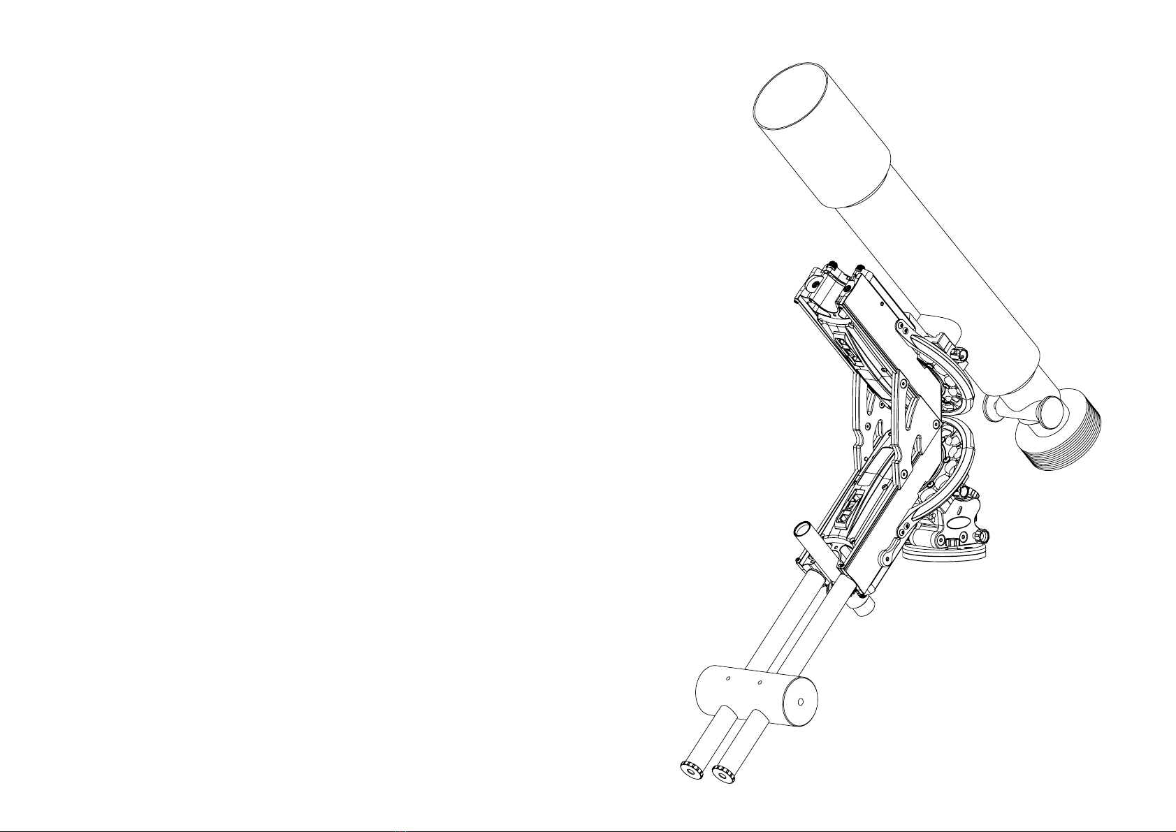
The patent pending modular design of the AstroTrac 360
system minimises travel weight. You can configure it as a
single axis Tracker or a two axis Single Arm or German
Equatorial mount to suit your imaging needs.
Each AstroTrac 360 Drive has built in WiFi, and a web
server which sends the device independent control
interface to a web browser running on your favourite WiFi
enabled device. The control interface features a virtual
handpad for slewing your AstroTrac 360, access to settings
and updating of the firmware and user interface.
If you prefer not to use a computer under the night sky,
your AstroTrac 360 also works in standalone mode, using
the previously saved tracking and autoguiding settings on
power up.

Revision 1.0
360 Drive Overview
3
2x Dovetail Rail
Stop Screws
ST-4 Guide
Port
12 V DC
Jack Socket
(centre +ve)
Dec Link
Encoder
Status Led
Clutch Lever (shown in closed position)
Dovetail Rail
Chassis
Wheel
Wheel Guard
3x Electronic
Polarfinder
Mounting
2x Counterweight
Bar Mounts
3x Polar Scope
Adjusters Polar Scope
Slot
Tracking
Status Led
General
Status Led
GEM Configuration
Dec Drive Interface
and Location Dowel

Revision 1.0
4
Configuring your AstroTrac 360
Focal Length
(mm)
Recommended
Configuration
Instrument
Mounting Method Autoguiding Counterweights
< 200 Tracker
First OmniClamp mounted to Drive
Dovetail Rails.
Single Camera: ballhead mounted to first
OmniClamp.
Two cameras: second OmniClamp
mounted back to back with first. Two
ballheads and cameras mounted on
Vixen Dovetail Bar.
RA only None
200 - 400 Single Arm
OmniClamp mounted to Dec Drive
Wheel. Camera lens foot mounted to
Vixen Dovetail Bar.
RA & Dec None
> 400 German Equatorial
OmniClamp mounted to Dec Drive
Wheel. Telescope mounted to Vixen
Dovetail Bar.
RA & Dec Required
When using your AstroTrac 360 for the first time, you may find the below table useful as a starting point for choosing an
AstroTrac 360 configuration suitable for your camera and lens/telescope:

Revision 1.0
5
360 Edition Wedge
Overview
Your 360 Edition Wedge provides a rigid mounting for your
AstroTrac 360, with fine adjustment for accurate polar
alignment. Your Wedge covers the full 90 degree latitude
range from pole to equator.
Mounting to your tripod
You can mount your Wedge on a photo tripod standard
3/8”-16 UNC camera thread.
Mounting to your pier
If you already own an AstroTrac TP3065 Pier you can
securely mount your Wedge to it using 3x M8x8 mm
socket countersunk screws.
Attaching your 360 Drive to your Wedge
Your AstroTrac 360 RA drive attaches to your Wedge with
three M4x12 mm socket head cap screws. Alternatively,
you can use the 360 Quick Release Kit which is available
separately.
360 Drive Mounting
Plate
Latitude
Fine Adjust
Knob
Latitude
Lock
Lever
2x Front
Azimuth
Lock Knobs
Rear Azimuth
Lock Knob
2x Azimuth
Fine Adjust
Knobs
Latitude
Scale
Latitude Coarse
Adjust Set
Screw and
bubble level this
side
Base

Revision 1.0
360 Edition Wedge
Levelling
Polar alignment is made easier by leveling the Wedge with
the built in Bubble Level. Adjust the tripod leg lengths until
the bubble is centered in the Bubble Level circle when
viewed from directly above.
Aligning North
You can align your Wedge due north by sighting through
the polar scope at night or by using a compass during the
day. Rough alignment can be achieved by rotating your
tripod.
To fine tune alignment, gently undo the two Front and the
Rear Azimuth Lock Knobs a fraction of a turn until your
Wedge can be rotated by turning the 2x Azimuth Fine
Adjustment Knobs in opposite directions to each other. It is
advisable to keep the Front & Rear Azimuth Lock Knobs
slightly done up at all times to prevent wobble.
Bubble Level
Rear Azimuth
Lock Knob
2x Azimuth
Fine Adjust
Knobs
2x Front
Azimuth
Lock
Knobs
6

Revision 1.0
360 Edition Wedge
Setting your Latitude
1. Release the Latitude Lock Lever
2. Locate and loosen the Latitude Coarse Adjust Set
Screw (accessible through hole in side plate)
3. Rotate the 360 Drive Mounting Plate until the
Latitude Scale pointer is indicating your latitude:
4. Gently tighten the Latitude Coarse Adjust Set Screw
until resistance is felt. Be careful not to overtighten or
you may damage the thread.
5. Make fine adjustments in latitude using the Latitude
Fine Adjust Knob. Gently tighten the Latitude Lock
Lever when you are finished.
Latitude
Lock Lever
Latitude
Scale
pointer
360 Drive
Mounting
Plate
Latitude
Scale
Latitude Coarse
Adjust Set Screw
Latitude
Fine Adjust
Knob
7

Revision 1.0
360 Edition Wedge
Attaching your AstroTrac 360 RA drive
A. With the supplied 3x M4 mm screws
Use the 3x M4 mm socket head cap screws and hex
wrench to attach your AstroTrac 360 RA drive to the 360
Drive Mounting Plate.
(hint: adjusting the Wedge latitude to the equator zero
degrees latitude position before inserting the screws gives
better access)
8
3x M4x12 mm socket
head cap screws

Revision 1.0
360 Edition Wedge
Attaching your AstroTrac 360 RA drive
B. With the optional Wedge Quick Release Kit
1. Remove the 4x M4x12 mm hexagon socket head
screws securing the 360 Drive Mounting Plate.
2. Attach the Quick Release Kit Dovetail Plate with 4x
M6x16 mm hexagon socket countersunk screws.
3. Locate the 2x M4x12 mm hexagon socket head Stop
Screws to prevent the OmniClamp sliding off the
Dovetail.
4. Attach the OmniClamp to the 360 Drive Wheel with
4x M5x10 mm hexagon socket countersunk screws.
5. Slide the OmniClamp onto the Quick Release Kit
Dovetail Plate until it contacts the 2x M4 Stop
Screws.
6. Tighten the OmniClamp Lock Knob. Insert the hex
key through the OmniClamp Lock Knob through hole
to provide more leverage and tighten firmly.
9
2x M4x12 mm
stop screws
4x M5x10 mm
screws
Dovetail Plate
2x M4x12 mm
Stop Screws
OmniClamp
Lock Knob
Hex
key

Revision 1.0
10
Tracker Configuration
1. Mount your AstroTrac 360 Drive on your Wedge with
the Chassis vertical (to reduce risk of gear falling off!)
2. Release the OmniClamp Lock Knob and slide your
OmniClamp onto the Dovetail Rails.
3. Screw your ball head firmly onto the ⅜-16
OmniClamp stud.
4. Open the RA Drive Clutch and rotate the RA Drive so
it’s horizontal. Balance your camera and lens by
sliding the OmniClamp along the Dovetail Rails. Use
a hex key through the cross bore in the OmniClamp
Lock Knob to ensure the OmniClamp can’t slide off.
5. Follow the polar alignment procedure as described in
the Polar Alignment section.
6. By mounting a second OmniClamp back to back with
the first OmniClamp, it is possible to use a Vixen
dovetail bar to mount two or more ballheads and
cameras.
Dovetail Rails
OmniClamp
Lock knob
⅜-16 stud
RA Drive
horizontal for
RA balancing

Revision 1.0
11
Drive Clamps
The Drive Clamps are used to mount the Dec Drive to the
RA Drive in the Single Arm and German Equatorial
configurations as follows:
1. Rotate the RA Drive so its vertical. Close the Clutch
and ensure the 2x M3 hex socket head Rail Stop
screws are in place to prevent the Dec Drive
accidentally sliding off.
2. Ensure the 3x M5 hex socket countersunk Drive
Clamp Lock Screws are loosened one full turn on
each Drive Clamp. If the Drive Clamp is tight getting
it started on the Dovetail Rails, use a little light
lubricant.
3. The Drive Clamp/Dovetail Rail fits are closely
toleranced. If you feel jamming, don’t force them.
Apply lubricant and gently wiggle until the Drive
Clamps slide onto the Dovetail Rails.
4. Once you’ve mounted the Dec Drive to the Drive
Clamps, you can gently tighten the Drive Clamp Lock
screws, ensuring the hex key is fully engaged with
the hex socket in the head of the 3x M5 hex socket
countersunk Drive Clamp Lock screws. Don’t over
tighten or you may strip the hex socket in the head of
the screw which will make removal and replacement
difficult.
Drive Clamps
Dovetail Rails
3x Drive Clamp
Lock Screws

Revision 1.0
12
Single Arm Configuration
1. Rotate the RA Drive so it’s vertical and attach a pair
of Drive Clamps to the RA Drive (see Drive Clamp
section), leaving the Drive Clamp Lock Screws a little
loose.
2. Slot the Dec Drive down into the Drive Clamps until
the end of the Dec Drive touches the RA Drive.
3. Whilst holding the Dec Drive to prevent it sliding off
the RA Drive, open the RA Drive Clutch, and rotate
the RA Drive through 90 degrees until it is horizontal.
4. Slide the Dec Drive to and fro along the RA Dovetail
Rails until your camera and lens is balanced in RA.
5. Gently tighten the Drive Clamps Lock screws (see
precautions in Drive Clamp section).
6. Attach an OmniClamp to the Dec Drive Wheel.
7. Mount your camera and lens on a Vixen Dovetail
Plate and clamp with the Dec Drive OmniClamp.
8. Open the Dec Drive Clutch, rotate the Dec Drive
Wheel until your camera and lens is horizontal and
balance by sliding to and fro in the OmniClamp.
Once balanced in Dec, firmly lock the OmniClamp.
RA Clutch
RA Drive horizontal
for RA balancing
Dec Drive
Instrument Mounting
OmniClamp horizontal
for Dec balancing

Revision 1.0
13
German Equatorial Configuration
Mounting the RA Drive
1. Mount a 360 Drive on your Wedge with the Chassis
vertical (to prevent the Dec Drive accidentally sliding
off whilst you are mounting it).
2. Screw both Counterweight Bars into the M10 threads
at the Polar Scope end of the RA Drive Chassis.
3. Loosen the Counterweight Lock Screws and slide the
Counterweight onto both Counterweight Bars.
4. Whilst holding the Counterweight, screw both
Counterweight Bar End Stops into the ends of the
Counterweight Bars.
5. Slide the counterweight so it touches the
Counterweight Bar End Stops.
Counterweight
Lock Screws
Counterweight
Bar End Stops
Counterweight
Bars

Revision 1.0
14
German Equatorial Configuration
Mounting the Dec Drive
1. Attach a pair of Drive Clamps to the RA drive (see
Drive Clamp section), leaving the Drive Clamp Lock
Screws a little loose.
2. Position the Drive Clamps so they are protruding a
little from the GEM Interface end of the RA Drive.
3. Slide the Dec Drive Dovetail Rails down into the
Drive Clamps until the Dec Drive GEM Interface is
about 10 mm away from the RA Drive.
4. Simultaneously slide the Dec Drive down and
towards the RA drive (as shown by the dotted
arrows) so the GEM Interface Location Dowels go
into their respective mating holes in the other Drive.
5. It may be necessary to gently wiggle the Dec Drive
and Drive Clamps to get the Location Dowels into
their respective holes.
6. Ensure the Dec and RA Drive GEM Interfaces are in
full contact and gently tighten the Drive Clamp Lock
Screws (see precautions in Drive Clamp section).
7. Attach an OmniClamp to the Dec Drive Wheel.
Drive
Clamp
protruding
Drive Interface
Location Dowels

Revision 1.0
15
German Equatorial Configuration
Balancing the RA and Dec Drives
1. Place the RA Drive and Counterweight Bars into a
vertical position and close the RA Clutch (page 13).
2. Place the Dec Drive OmniClamp in a horizontal
position and close the Dec Clutch (this page).
3. Attach your camera and telescope to a Vixen
Dovetail Bar. Slide the Vixen Dovetail Bar into the
Dec Drive OmniClamp. Tighten the OmniClamp Lock
Knob and check your telescope is secure.
4. Whilst holding your telescope, open the RA Clutch,
and rotate the RA Drive through 90 degrees until the
Counterweight Bars are horizontal.
5. Slide the Counterweight along the Counterweight
Bars until your camera and telescope are balanced
in RA. Close the RA Clutch.
6. Open the Dec Drive Clutch. Rotate the Dec Drive
Wheel until your camera and telescope are
horizontal and balance by sliding to and fro in the
OmniClamp. Insert a hex key through the
OmniClamp Lock Knob and use it as a lever to
tighten the Knob (page 9).
Place OmniClamp horizontal
and slide telescope dovetail to
balance Dec
Place Counterweight Bars
horizontal and slide Counterweight
to balance RA

Revision 1.0
360 Polar Scope Overview
For high quality unguided tracking (without ST-4
autoguider) and guided tracking (with ST-4 autoguider),
you will need to align your AstroTrac 360 RA Drive’s axis of
rotation with the axis of rotation of the sky. This process is
known as polar alignment and achieved by adjusting your
Wedge in azimuth and altitude.
There are no stars exactly coincident with the north and
south celestial poles. The AstroTrac 360 Polar Scope
reticle has been designed to make it easy to polar align
using stars close to the celestial poles.
Polar alignment accuracy depends on focal length and
exposure duration. As a rule of thumb, it’s advisable to aim
for polar alignment accuracy of 5 arcminutes or better for
trail free images.
For unguided long duration (> 5 mins), long focal length (>
200 mm) exposures, it is advisable to use an electronic
polar alignment aid, such as a Polemaster camera or
SharpCap software. Polar alignment within a few
arcseconds then becomes possible.
Alternatively, autoguiding via the ST-4 port will eliminate
small polar alignment errors, but it’s still important to
achieve polar alignment accuracy of 5 arcminutes or
better for good results.
Objective Lens Tube
Mounting Disc
Mounting Disc
Lock Nut
3x Reticle
Collimation
Set Screws
3x Reticle
Illumination
Slots
Eyepiece
Body
16

Revision 1.0
360 Polar Scope Installation
1. Adjust the three Polar Scope Thumbscrews so they
are protruding into the Polar Scope Slot by no more
than 0.25 - 0.5 mm.
2. Locate the Polar Scope Washer in the slot and push
until there’s a click. Ensure the Polar Scope Body is
concentric with the Polar Scope Recess.
3. The Polar Scope should click into place and rotate
without excessive force. If it feels tight, back off the
three Polar Scope Thumbwheels a little, maintaining
contact between the tips of the thumbscrews and the
Polar Scope Mounting Disc.
4. It is advisable to rotate the Polar Scope by gripping
and turning the Polar Scope Body. Rotating the
objective lens tube may cause it to unscrew from the
Polar Scope Body.
5. With the Polar Scope illumination on (see Control
section), the reticle markings will illuminate red in low
ambient light levels.
6. There’s no need to remove the Polar Scope when
not in use, it can be left in place and its mass will
help counterbalance your camera and lens/scope.
3x Polar Scope
Thumbscrews
Polar Scope Slot
Polar Scope
Recess
17

Revision 1.0
360 Polar Scope Setup
Centering The Reticle
For accurate polar alignment, the Polar Scope Reticle
must be centered on the Polar Scope’s optical axis:
1. Mount your 360 RA Drive on your Wedge and install
the Polar Scope as described in the previous section.
2. Look through the Polar Scope and identify the central
point in the reticle pattern where the radiating lines
intersect. This is the reticle centre.
3. Align the reticle centre on a distant fixed object. Use
a faraway object during the day, or a star at night.
4. Close the RA Drive Clutch so the Drive Wheel
doesn’t rotate, and gently rotate the Polar Scope
through 180 degrees in it’s housing. If the reticle isn’t
centred with the optical axis of the Polar Scope, the
reticle centre will move off the distant object.
5. Adjust the three reticle centering screws in small
steps to halve the offset distance of the distant
object from the reticle centre.
6. Repeat steps 4 & 5 until the reticle is centred.
18
POLARIS
2000
2030
51 Cep
σ Oct
Oct
α Eri
δ UMi
χ
2000
2015
2030
2030
2015
2000
Move to
here
If star
here

Revision 1.0
360 Polar Scope Setup
RA Axis Alignment
For accurate polar alignment, the Polar Scope’s optical
axis must be aligned with the RA Drive’s axis of rotation. It
may save you time if you carry out this procedure
immediately after centering the polar scope reticle:
1. Mount your 360 RA Drive on your Wedge and install
the Polar Scope and centre the reticle as described
in the previous sections.
2. Align the reticle centre on a distant object. Use a
point like feature during the day, such as the tip of a
pylon, or a star at night.
3. Release the RA Clutch and rotate the RA Drive
through 180 degrees. Re-engage the RA Clutch.
4. If the distant object has moved off the reticle centre,
adjust the 3x Polar Scope Thumbscrews so as to
halve the offset distance.
5. Repeat steps 3 & 4 until the offset is eliminated and
the distant object remains at the reticle centre.
19
Rotate RA Drive
through 180 degrees

Revision 1.0
360 Polar Alignment
Northern Hemisphere
1. With one eye looking through the Polar Scope at the
Ursa Major and Cassiopeia reticle marks, and the
other eye looking directly at the sky, rotate the Polar
Scope until the Ursa Major and Cassiopeia reticle
marks are roughly aligned with the sky (neither
constellation will be visible through the Polar Scope).
2. Adjust your Wedge Azimuth and Altitude Fine Adjust
Knobs to position Polaris in the gap in the line
marked ‘POLARIS’.
3. For longer focal lengths you can fine tune polar
alignment by placing the stars 51 Cephei and Delta
Ursa Major into the positions labelled ‘51 Cep and ‘δ
UMi’ respectively.
4. The lines radiating from the reticle centre represent
the year 2000, the next short line 2015 and the final
short line 2030. If the current year falls between pairs
of lines, position the stars correspondingly: e.g. in
2020, position the stars ⅓ of the distance from the
2015 line to the 2030 line.
5. Use small rotations of the Polar Scope and
adjustments to the Wedge azimuth and altitude.
20
2000
2015
2030
2030
2015
2000
2000
2015
2030
2030
2015
2000
POLARIS
2000
2030
51 Cep
σ Oct
Oct
α Eri
δ UMi
χ
2000
2015
2030
2030
2015
2000
Table of contents