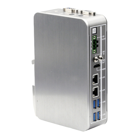
Asus Tinker System 2 Series User manual

Tinker System 2
Series
User Manual

COPYRIGHT INFORMATION
No part of this manual, including the products and software described in it, may be reproduced,
transmitted, transcribed, stored in a retrieval system, or translated into any language in any form or by
any means, except documentation kept by the purchaser for backup purposes, without the express
written permission of ASUSTeK COMPUTER INC. (“ASUS”).
ASUS PROVIDES THIS MANUAL“AS IS”WITHOUT WARRANTY OF ANY KIND, EITHER EXPRESS
OR IMPLIED, INCLUDING BUT NOT LIMITED TO THE IMPLIED WARRANTIES OR CONDITIONS OF
MERCHANTABILITY OR FITNESS FOR A PARTICULAR PURPOSE. IN NO EVENT SHALL ASUS, ITS
DIRECTORS, OFFICERS, EMPLOYEES OR AGENTS BE LIABLE FOR ANY INDIRECT, SPECIAL, INCIDENTAL,
OR CONSEQUENTIAL DAMAGES (INCLUDING DAMAGES FOR LOSS OF PROFITS, LOSS OF BUSINESS,
LOSS OF USE OR DATA, INTERRUPTION OF BUSINESS AND THE LIKE), EVEN IF ASUS HAS BEEN ADVISED
OF THE POSSIBILITY OF SUCH DAMAGES ARISING FROM ANY DEFECT OR ERROR IN THIS MANUAL OR
PRODUCT.
Products and corporate names appearing in this manual may or may not be registered trademarks or
copyrights of their respective companies, and are used only for identification or explanation and to
the owners’benefit, without intent to infringe.
SPECIFICATIONS AND INFORMATION CONTAINED IN THIS MANUAL ARE FURNISHED FOR
INFORMATIONAL USE ONLY, AND ARE SUBJECT TO CHANGE AT ANY TIME WITHOUT NOTICE, AND
SHOULD NOT BE CONSTRUED AS A COMMITMENT BY ASUS. ASUS ASSUMES NO RESPONSIBILITY OR
LIABILITY FOR ANY ERRORS OR INACCURACIES THAT MAY APPEAR IN THIS MANUAL, INCLUDING THE
PRODUCTS AND SOFTWARE DESCRIBED IN IT.
Copyright © 2022 ASUSTeK COMPUTER INC. All Rights Reserved.
LIMITATION OF LIABILITY
Circumstances may arise where because of a default on ASUS’ part or other liability, you are entitled to
recover damages from ASUS. In each such instance, regardless of the basis on which you are entitled
to claim damages from ASUS, ASUS is liable for no more than damages for bodily injury (including
death) and damage to real property and tangible personal property; or any other actual and direct
damages resulted from omission or failure of performing legal duties under this Warranty Statement,
up to the listed contract price of each product.
ASUS will only be responsible for or indemnify you for loss, damages or claims based in contract, tort
or infringement under this Warranty Statement.
This limit also applies to ASUS’suppliers and its reseller. It is the maximum for which ASUS, its
suppliers, and your reseller are collectively responsible.
UNDER NO CIRCUMSTANCES IS ASUS LIABLE FOR ANY OF THE FOLLOWING: (1) THIRD-PARTY
CLAIMS AGAINST YOU FOR DAMAGES; (2) LOSS OF, OR DAMAGE TO,YOUR RECORDS OR DATA; OR (3)
SPECIAL, INCIDENTAL, OR INDIRECT DAMAGES OR FOR ANY ECONOMIC CONSEQUENTIAL DAMAGES
(INCLUDING LOST PROFITS OR SAVINGS), EVEN IF ASUS, ITS SUPPLIERS OR YOUR RESELLER IS
INFORMED OF THEIR POSSIBILITY.
SERVICE AND SUPPORT
Visit our multi-language web site at https://www.asus.com/support/
Revised Edition
June 2023
E22240

ASUS Tinker System 2 Series
3
Contents
About this manual.................................................................................................................4
Conventions used in this manual....................................................................................4
Product Overview..................................................................................................................5
Tinker System 2 Series specications summary.........................................................5
Package contents ..................................................................................................................6
Getting to know your Tinker System 2
Features.....................................................................................................................................8
Front view ................................................................................................................................8
Left view...................................................................................................................................10
Rear view..................................................................................................................................11
Single Board Computer Overview...................................................................................12
Single Board Computer (SBC) layout.............................................................................12
Using your Tinker System 2
Getting started .......................................................................................................................22
Install the operating system..............................................................................................22
Connect a display to your Tinker System 2..................................................................24
Connect keyboard and mouse.........................................................................................26
Connect an AC power adapter.........................................................................................27
Appendix
Safety information.................................................................................................................30
Setting up your system.......................................................................................................31
Care during use......................................................................................................................31
Restricted Access Location................................................................................................32
Safety Precautions ................................................................................................................32
Regulatory notices ................................................................................................................33
Service and Support.............................................................................................................40

4
ASUS Tinker System 2 Series
About this manual
This manual provides information about the hardware and software features
of your Tinker System 2, organized through the following chapters:
Chapter 1: Getting to know your Tinker System 2
This chapter details the hardware components of your Tinker System 2.
Chapter 2: Using your Tinker System 2
This chapter provides you with information on using your Tinker
System 2.
Appendix
This section includes notices and safety statements for your Tinker
System 2.
Conventions used in this manual
To highlight key information in this manual, some text are presented as
follows:
IMPORTANT! This message contains vital information that must be
followed to complete a task.
NOTE: This message contains additional information and tips that
can help complete tasks.
WARNING! This message contains important information that must
be followed to keep you safe while performing certain tasks and
prevent damage to your Tinker System 2's data and components.

ASUS Tinker System 2 Series
5
Product Overview
Tinker System 2 Series is more than a dream for the DIY-obsessed: it’s a
gateway to new ideas and new relationships. Experienced makers will love
Tinker Board’s performance-to-price ratio and strong brand heritage, while
novices and younger users will appreciate its accessibility and ease of use.
But all will come together to create — Together We Make!
Tinker System 2 Series specications summary
SoC Rockchip RK3399 (64-bit)
CPU Dual-core Arm® Cortex®-A72 @ 2.0 GHz
Quad-core Arm® Cortex®-A53 @ 1.5 GHz
GPU Arm® Mali™-T860 MP4 GPU @ 800 MHz
Display
1 x HDMI™ with CEC hardware ready
1 x USB Type-C® (DP 1.2)
1 x 22-pin MIPI DSI (4 lane) supports up to FHD
Memory Size Dual-CH LPDDR4 2GB or 4GB
Storage 16/32GB eMMC
Connectivity RTL8211F-CG GbE LAN
M.2 - 802.11 a/b/g/n/ac wireless & BT 5.0 (2T2R)
Audio
1 x HDMI™ audio output
1 x S/PDIF TX pin (from GPIO)
1 x PCM/I2S pins (from GPIO)
USB 3 x USB 3.2 Gen 1 Type-A ports
1 x USB 3.2 Gen 1 Type-C® OTG port
Camera Interface 1 x 15-pin MIPI CSI-2 (2 lane)
Internal Headers
1 x 2-pin Recovery header
1 x 2-pin Power-on header
1 x 2-pin Reset header
1 x 2-pin Debug UART header
1 x 2-pin DC Fan header
1 x 2-pin RTC Battery header
Power Connector
(up to 45W) 1 x 12~19.5 V DC Power Input Jack (5.5/2.5 mm)
OS Support Debian 10 / Android 11
Dimension 3.58” x 2.64” x 1.77”(91 mm x 67 mm x 45 mm)

6
ASUS Tinker System 2 Series
Package contents
Your Tinker System 2 package contains the following items:
ASUS Tinker System 2 Series
2 x Wi-Fi/BT antennas Technical documentation
NOTES:
• Some bundled accessories may vary depending on the model. For
details on these accessories, refer to their respective user manuals.
• The device illustration is for reference only. Actual product
specifications may vary depending on the model.
• If the device or its components fail or malfunction during normal
and proper use within the warranty period, bring the warranty
card to the ASUS Service Center for replacement of the defective
components.

1
Getting to know your Tinker
System 2

8
ASUS Tinker System 2 Series
Features
Front view
MIPI DSI (4 lane) slot
This slot allows you to connect a MIPI display module via a 4 lane
MIPI-DSI cable for up to 6Gbps connection speed.
LAN port
The 8-pin RJ-45 LAN port supports a standard Ethernet cable for
10/100/1000Mbps connection to a local network.
ACT/LINK LED SPEED LED
LAN port
Activity Link LED
Status Description
Off No link
Yellow Linked
Yellow (blinking) Data activity
Yellow (blinking
then steady)
Ready to wake
up from suspend
mode
Speed LED
Status Description
Off 10 Mbps connection
Orange 100 Mbps connection
Green 1 Gbps connection

ASUS Tinker System 2 Series
9
USB 3.2 Gen 1 Type-C® On-The-Go (OTG) port
This USB 3.2 Gen 1 Type-C® OTG port provides the following:
• Transfer rate of up to 5 Gbit/s for USB 3.2 Gen 1 devices.
• Support for Power Delivery with a maximum of 5V/1.5A
output.
• Backward compatible to USB 2.0.
• Support for OTG mode that allows this device to read data
from a USB device even when it’s not connected to a PC.
• Support for DP 1.2 with a resolution of up to 4096 x 2160
@60Hz.
USB 3.2 Gen 1 port
The USB 3.2 Gen 1 (Universal Serial Bus) port provides a transfer
rate up to 5 Gbit/s.

10
ASUS Tinker System 2 Series
Power input jack
This 5.5/2.5mm DC-in jack supplies power to Tinker System 2.
To prevent damage to the device, use only UL certified power
adapters that meet the following specifications:
Power adapter: +12~19.5V DC 3.75~2.31A, 45W
WARNING! The power adapter may become warm to hot
when in use. Do not cover the adapter and make sure to
keep it away from your body.
HDMITM port
The HDMI™ (High Definition Multimedia Interface) port supports
a Full-HD device, such as an LCD TV or monitor, to allow viewing
on a larger external display.
NOTE: When using only this port as a display output
source, this port will support a resolution of up to 4096 x
2160 @60Hz. The resolution may also be affected by the
cabling and output device.
Left view

ASUS Tinker System 2 Series
11
Rear view
MIPI CSI slot
This slot allows you to connect a MIPI camera module via a 2 lane
MIPI-CSI2 cable for up to 3Gbps connection speed.
Wi-Fi/Bluetooth wireless antenna jack
The Wi-Fi/Bluetooth wireless antenna jack allows you to connect
wireless antennas for Wi-Fi or Bluetooth signals.
NOTE: The Wi-Fi/Bluetooth wireless antenna is optional
and may not come bundled.
Status LEDs
The Status LEDs indicate the current status of your Tinker System 2.
Power LED
Disk Activity LED
Reserved LED
(Programmable)
Status LED Indication
LED Color
Power Red
Disk Activity Green
Reserved (programmable) Yellow

12
ASUS Tinker System 2 Series
Single Board Computer Overview
ASUS Tinker System 2 is an Embedded Computer based on the Tinker
Board 2S. Refer to the Layout contents table for the page numbers of the
numbered items.
WARNING!
• Unplug the power cord from the wall socket before touching any
components.
• Before handling components, use a grounded wrist strap or touch
a safely grounded object or a metal object, such as the power
supply case, to avoid damaging them due to static electricity.
• Hold components by the edges to avoid touching the ICs on them.
• Whenever you uninstall a component, place it on a grounded anti-
static pad or in the bag that came with the component.
• Before you install or remove any component, ensure that the
power supply is switched off or the power cord is detached from
the power supply. Failure to do so may cause severe damage to
the single board computer, peripherals, or components.
Single Board Computer (SBC) layout
Top view
DSI
SOC RK3399
M.2 (WIFI)
LAN
U31G1_3
U31G2_C1
U31G1_12
DC HDMI
J3
J5
J6
LED2
LED3
LED1 FAN
CSI
J2
RTC_BAT
1
3
7 6 5
4
9
8
10
11
2

ASUS Tinker System 2 Series
13
Bottom view
LPDDR4
LPDDR4 eMMC
USB HUB
LAN phy
Layout contents Page
1. GPIO header 14
2. SOC RK3399 15
3. Debug UART header 16
4. Reset header 16
5. MIPI DSI connector 16
6. DC Fan header 17
7. Power-on header and Maskrom jumper 17
8. Status LEDs 18
9. MIPI CSI-2 connector 18
10. RTC Battery header 19
11. M.2 Wi-Fi slot 19
12. Micro SD Card slot 20

14
ASUS Tinker System 2 Series
1. GPIO header
This 40-pin GPIO (General-Purpose Input/Output) header can be
designated (in software) as an input or output pin and is used for a
wide range of purposes. Of the 40 pins, 28 are GPIO pins (shared with
SPI/UART/I2C pins).
Tinker Board 2 / 2S 40-pins GPIO header
40P_GPIO
1
2
3
4
5
6
7
8
9
10
11
12
13
14
15
16
17
18
19
20
21
22
23
24
25
26
27
28
29
30
31
32
33
34
35
36
37
38
39
40
WARNING!
• Do not use both the system DC power-in jack and the 40-pin GPIO
+5V pins (pin 2 and 4, red) for power input at the same time.
• If you wish to use the 40-pin GPIO +5V (pin 2 and 4, red) as a
power input source, please make sure the power input rating for
each pin complies with the standard of +5V / 3A (+/-5% deviation).
A power rating value that exceeds the rating valued mentioned, or
an unstable power source may result in damage to your system or
hardware. Please refer to the Top view illustration for the location
of the pins.

ASUS Tinker System 2 Series
15
Pin Denitions
Pin definition 40P GPIO Pin definition
VCC3.3_IO 1 2
VCC5V
GPIO2_B1/I2C6_SDA 3 4
GPIO2_B2/I2C6_SCL 5 6 GND
GPIO0_B0/CLKOUT 7 8 GPIO2_C1/UART0_TX
GND 9 10 GPIO2_C0/UART0_RX
GPIO2_C3/UART0_RTSN 11 12 GPIO3_D1/I2S0_SCLK
GPIO2_C5/SPI5_TXD 13 14 GND
GPIO2_C4/SPI5_RXD 15 16 GPIO2_C6/SPI5_CLK
VCC3.3_IO 17 18 GPIO2_C7/SPI5_CSN0
GPIO1_B0/SPI1_TXD/UART4_TX 19 20 GND
GPIO1_A7/SPI1_RXD/UART4_RX 21 22 GPIO3_D4/I2S0_SDI1SDO3
GPIO1_B1/SPI1_CLK 23 24 GPIO1_B2/SPI1_CSN0
GND 25 26 GPIO0_A6/PWM3A_IR
GPIO2_A7/I2C7_SDA 27 28 GPIO2_B0/I2C7_SCL
GPIO3_D6/I2S0_SDI1SDO1 29 30 GND
GPIO3_D5/I2S0_SDI1SDO2 31 32 GPIO4_C2/PWM0
GPIO4_C6/PWM1 33 34 GND
GPIO3_D1/I2S0_LRCK 35 36 GPIO2_C2/UART0_CTSN
GPIO4_C5/SPDIF_TX 37 38 GPIO3_D3/I2S0_SDI0
GND 39 40 GPIO3_D7/I2S0_SDO0
2. SOC RK3399
This ARM® system on a chip (SoC) features the new 64-bit Armv8
architecture and Arm® big.LITTLE™ technology’s 6-core processor,
provides improved performance and comes bundled with Arm®
Mali®-T860 MP4 GPU.

16
ASUS Tinker System 2 Series
3. Debug UART header
This Debug UART header provides a separate UART port, allowing
developers to use and develop with the serial console without
occupying the 40-pin GPIO’s UART ports.
4. Reset header
The Reset header allows you to connect an external reset button.
5. MIPI DSI connector
The MIPI DSI connector is used to connect a MIPI display module via a 4
lane MIPI-DSI cable. This connector supports up to 6 Gbps connection
speed.

ASUS Tinker System 2 Series
17
6. DC Fan header
The DC Fan header allows you to connect a fan to actively cool the
system.
Connector Type JST PH 2P 2.00mm
Reference PN: JST, PHR-2
WARNING!
• These are not jumpers! Do not place jumper caps on the fan
connectors.
• Ensure the cable is fully inserted into the connector.
NOTE: The fan is purchased separately.
7. Power On header and Maskrom jumper
The Power On header allows you to connect an external power button.
The Maskrom jumper allows you to mask the eMMC (rom) for recovery.
This will allow you to enter developer mode due to the indetected
storage and rewrite the eMMC.

18
ASUS Tinker System 2 Series
8. Status LEDs
The Status LEDs indicate the current status of the Single Board
Computer.
LED Indication
LED3 (Yellow) Reserved (Programmable)
LED2 (Green) Disk Activity
LED1 (Red) Power
9. MIPI CSI connector
The MIPI CSI connector is used to connect a MIPI camera module via a 2
lane MIPI-CSI2 cable. This connector supports up to 3 Gbps connection
speed.
WARNING! Ensure the cable for MIPI CSI is connected in the correct
orientation with the gold ngers facing towards the rear of the Single
Board Computer.

ASUS Tinker System 2 Series
19
10. RTC Battery header
The RTC Battery header allows you to connect the lithium battery.
11. M.2 Wi-Fi Slot (E-Key)
The M.2 Wi-Fi slot allows you to install an M.2 Wi-Fi module (E-key, type
2230).
WARNING! Disconnect all power (including redundant PSUs) before
you add or remove a memory card, and then reboot the system to
access the memory card.

20
ASUS Tinker System 2 Series
12. Micro SD Card slot*
The microSD card slot allows you to install a microSD memory card
v2.00 (SDHC) / v3.00 (SDXC) for storage.
WARNING! Disconnect all power (including redundant PSUs) from
the existing system before you add or remove a memory card, then
reboot the system to access the memory card.
* The Micro SD Card slot is located under the dust cover on the right side of the
device.
Table of contents
Other Asus Desktop manuals

Asus
Asus BS5000 User manual

Asus
Asus D800SDR User manual

Asus
Asus GT51CH User manual

Asus
Asus BM3CD User manual

Asus
Asus AAEON BOXER-8251AI Operation manual

Asus
Asus Vintage AH1 User manual

Asus
Asus Essentio CP6230 User manual

Asus
Asus Vivo AiO V222F Series User manual

Asus
Asus P6-P7H55E User manual

Asus
Asus BP5268 User manual

Asus
Asus P3-P5G33 - P Series - 0 MB RAM User manual

Asus
Asus PN62S User manual

Asus
Asus G series User manual

Asus
Asus V-Series P5G965 User manual

Asus
Asus ET2311INKH User manual

Asus
Asus NOVA P20/22 User manual

Asus
Asus EB1030 User manual

Asus
Asus EeeBox EB1007 User manual

Asus
Asus PUNDIT-AE3 User manual

Asus
Asus V3-PH3 User manual