manuals.online logo
Brands
  1. Home
  2. •
  3. Brands
  4. •
  5. Shuttle
  6. •
  7. Desktop
  8. •
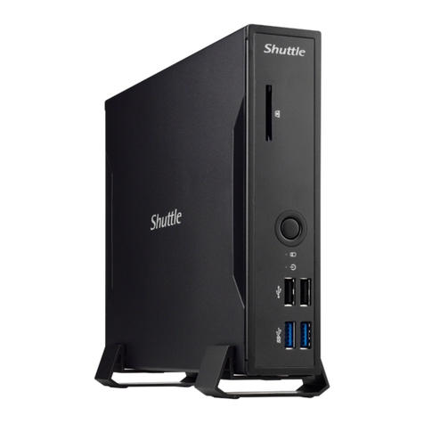
  9. Shuttle DS20U Series User manual

Shuttle DS20U Series User manual

󵤫󳃀󰈯󰉺󰉔󰉩󳵹󰆍󰇝󰇽󰇪󰇲󱄈󱺎󱛱󰇳󲥜󶥍󱄕󶚗󰇫󰇳󰇘󱆯󳝘󰇯󰇮󰈐󰈂󰇟󰈗󰆎
For safety reasons, please ensure that
the power cord is disconnected before
opening the case.
LThe product’s colour and specifications may vary from the actually shipping product.
A. Begin Installation
!
Hardware Installation 󳪜󵴄󶛙󶻃
󰉍󰉺󰉇󰈤󰈥󰈠󰇲󰈢󰉱󰈷󰉆󰉺󰉩󳪜󱄦󶛙󴫵
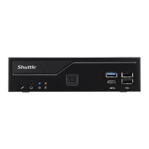
1. USB 3.2 Ports
(Celeron Gen 1, Core I Gen 2)
2. USB 2.0 Ports
3. Power LED
4. Hard Disk Drive LED
5. Power Button
6. SD Card Reader
7. MIC-in
8. Headphones
9. External Power SW & Clear CMOS
10. HDMI Port
11. DisplayPort
12. COM/VGA Port (RS232 only) (Option)
13. COM Port (RS232/RS422/RS485)
(BIOS Setting)
14. LAN Ports (Gigabit LAN)
15. Power Jack (DC IN)
16. Connector for WLAN antenna
17. Kensington®Lock Hole
1. Unscrew the two screws of the chassis
cover. Slide the cover backwards and
upwards.
1. Unfasten the rack mount screw and remove the rack.
B. HDD or SSD Installation
2. Place an HDD or SSD in the rack and secure
with two screws from each side.
3. Lay the HDD or SSD into its drive bay
and push it gently to the right until it
clicks into place. Refasten screws.
Please press the "Del" key while booting to enter BIOS. Here, please load the optimised BIOS settings.
Operation Position: Please make sure to use either the supplied feet or the VESA mount.
!
Safety Information
󶛙󶇰󴻷󶻽
󶛙󶇰󰇯󵟒󰇝󰈏󲋵󶙷󶛙󶇰󶖆󲊟
E. Complete
1. Please replace and affix the case
cover with two screws. Turn your
DS20U upside down.
2. Connect the power cord.
3. Complete.
e
f
d
1. Locate the SO-DIMM slots on the motherboard.
2. Align the notch of the memory module with the
one of the relevant memory slot.
3. Gently insert the module into the slot in a
45-degree angle.
4. Carefully push down the memory module
until it snaps into the locking mechanism.
5. Repeat the above steps to install an
additional memory module, if required.
D. M.2 Device Installation
C. Memory Module Installation
Latch Latch
Notch
Cutout
SO-DIMM slot
45-degree
angle
This motherboard does only support 1.2 V DDR4 SO-DIMM memory modules.
!
a
b
M.2 2242/2260/2280 M key slot
1. Locate the M.2 key slots on the motherboard.
2. Install the M.2 device into the M.2 slot and secure with the screw.
a
b
More information on this product can be found at: http://bit.ly/DS20U
󲤤󱭊󲥜󳝒󱛱󴻷󶻽󰦉󶽋󴛎󴐘󰦗
Weitere Informationen zu diesem Produkt finden Sie unter: http://bit.ly/DS20U
Pour plus d'informations sur ce produit, visitez: http://bit.ly/DS20U

󲥜󶻍󱛱󰇲󶼩󶰌󰇮󲋵󶙷󰇯󰇨󰇈󰇪󰇳󰆍󲵑󰇲󰈌󰈎󶭉󶼲󵨲󰇕󰈂󰇝󰆎

󲤤󱭊󲥜󱃗󱛱󶖆󲊟󰦉󴸧󴷯󵠞󰦗
Product Overview 󳝒󱛱󶚗󶻵󶻍󱛱󶤮󴮱󱃗󱛱󶚗󴯲
Incorrectly replacing the battery may damage this computer. Replace only with the same or equivalent as recommended by Shuttle. Dispose
of used batteries according to the manufacturer’s instructions.
󲤤󲘋󵤫󲺐󲟩󲄿󵕟󴳔󱘟󴌭󲤳󲘽󱬎󲥜󵤫󴎖󱄕󱗺󲅅󳢬󳐶󳋨󰆍󳊛󳊭󲑆󱎦󱄆󱖡󵣚󰆎󱋵󴌭󱇍󳢴󲄪󴶠󱄕󳤨󱘼󲑆󱘼󳵹󳢴󵤫󲺐󲤤󲘋󰆎󴳻󱇍󳎗󴬭󵉐󱝶󳢴󱆯󳝘󴳚󲠾󴢅
󳘶󲄒󵤫󲺐󰆎
Das unkorrekte Austauschen der Batterie kann diesen Computer beschädigen. Ersetzen Sie die Batterie nur durch den von Shuttle empfohlenen
Typ oder ein gleichwertiges Modell. Entsorgen Sie gebrauchte Batterien gemäß den Herstellerangaben.




󰉎󰉁󰉄󰉨󰈖󵟃󵊅󰇧󰇪󰈹󰉁󰉆󰇝󰈏󰇬󰆍󰇗󰇲󰈱󰉱󰉒󰉣󰉺󰈽󰇐󲘽󱋧󰇝󰈏󱗏󱤐󰇬󰇮󰈎󰈂󰇝󰆎󱃔󲘋󰇝󰈏󵣋󰇳󰆍󰇐󲗘󱮘󰇝󰈏󰉎󰉁󰉄󰉨󰇬󱘼󰇜󰈆󰇲󰈂󰇣󰇳
󱘼󳵹󰇲󰈆󰇲󰇤󰇕󰈖󱆯󳝘󰇝󰈏󰈌󰇊󰇯󰇛󰇪󰇓󰇤󰇙󰇈󰆎󱆯󳝘󳀸󰈃󰉎󰉁󰉄󰉨󰇳󰆍󰉟󰉺󰈩󰉺󰇲󲔷󳭪󰇯󲇃󰇧󰇪󱐖󱐶󰇛󰇪󰇓󰇤󰇙󰇈󰆎



󲤤󲖒󳝥󲺐󲟩󲄿󵝉󴸟󱘟󴌭󱅊󲖏󱥿󲥜󳝥󴍁󰆎󱃵󴌭󱇍󳢴󲄪󴷞󱄕󳤨󱘼󲑆󱘼󳵹󳢴󳝥󲺐󲤤󲖒󰆎󴸧󱇍󳎗󱑦󵉐󱝶󳢴󱆯󳝘󴸤󲠾󱬴󳘶󲃏󳝥󲺐󰆎
!
This device complies with Part 15 of the FCC Rules. Operation is subject to the following two conditions: (1) this device may not cause harmful
interference, and (2) this device must accept any interference received, including interference that may cause undesired operation.
This device meets the requirements for the EU conformity in accordance to the currently valid EU directives.


󲼘󶟞 󱃵󷀆󳝘󱂾󱥘󷄵󳌝󲁖󲹄󱉉󲦑󱄦󱀻󶛙󶇰󱆯󳝘
󱥘󳌝󲁖󲹄󱉉󲦑󱄦󱀻󱆯󳝘󲠦󱘟󶳬󲤹󶛙󶇰󵣀󲋓󰆎
󲼘󶟞 󶖼󴷨󱃗󱛱󱆯󳝘󳢴󶣟󷆫󳗟󶚃󳁙󶝲󱁪󰆎
2000m
󲼘󶟞 󱃵󷀆󳝘󱂾󶦵󲔄󱄕󱀻󶛙󶇰󱆯󳝘
󱥘󶦵󲔄󱄕󱀺󱆯󳝘󲠦󱘟󶳬󲤹󶛙󶇰󵣀󲋓󰆎
DS20U Series Quick Guide 󲈛󷀗󶛙󶻃󲔷󱖇󰆌󰆌󰆌󰆌󰈭󰈢󰉁󰈭󰈪󰈢󰉇󰆌󰆌󲈛󷀗󶛙󴫵󲔷󱖇
53R-DS20U3-2001
3 6
1 2 4 5 7 8
2
a
b
Slope angle
b
a
14 15
910 11 12 13
17 17
1
1616
b
a
2.5 inch HDD/SSD Slot
c
a
b
b
a
c
DC-IN
Please press the “Del” key while booting to enter BIOS. Here, please load the optimised BIOS settings.
Operation Position: Please make sure to use either the supplied feet or the VESA mount.
󶽋󶠰󶓺󱘼󲡲󱞏󱔅󷀞󱎕󷁄󵨵󶼌󶛡󵄹󱎕󶣟󱆣󶢈󶳬󳢴󶼌󶛡󱉬󰆎
󲛽󱆌󶡺󶢇󶢡󲄿󱆯󳝘󶝬󷁛󲝟󲛀󲧦󲑆󲡟󱤪󶛡󲧦󶢇󶲖󰆎






󳝫󵦒󰇯󱎕󰈏󰇣󰈅󰆍󶾹󱔅󱁝󰇯󰈫󰉺󰈖󲓬󰇛󰇪󰇓󰇤󰇙󰇈󰆎󶼌󶛡󳝫󵦒󰇐󶚲󰈂󰈎󰈂󰇝󰆎
󲛽󱆌󶕳󶲖󱄈󱺎󰇲󴿣󷁛󱐶󰈆󰇛󰇓󰇳󰉜󰈤󰉱󰉆󰈖󱆯󳝘󰇛󰇪󱀻󰇙󰇈󰆎



󴸧󶠰󵝞󱘼󲠦󱙟󱓘󵈋󱎕󵈹󵪩󴷮󶛡󱓐󵆭󶣟󱆣󶢈󶳬󳢴󴷮󶛡󱉬󰆎
󲛽󱆌󲙶󶢇󶢡󲄿󴸧󱆯󳝘󶝬󷁛󲝟󲛁󲧦󲑆󲡟󱤪󶛡󲧦󶢇󶲖󰆎
For safety reasons, please ensure that the power cord is disconnected before opening the case.
󱨪󶢢󶛙󶇰󶲳󵏿󳰫󵞻󶥍󶥺󲡲󶽋󱍸󲔄󵢔󵤫󳃀󶱉󰆎



󶛙󶇰󰇲󰇣󰈅󰇯󰆍󰈯󰉺󰈷󰈖󵞻󰇕󰈏󱑽󰇯󵤫󳃀󰈱󰉺󰉇󰈖󶚗󰇛󰇪󰇈󰈏󰇗󰇬󰈖󶭉󶼲󰇛󰇪󰇓󰇤󰇙󰇈󰆎


󱨪󱂾󶛙󶇰󶲳󴢁󳰫󲄰󲥪󱬣󲠦󴸧󱍸󲔄󵢔󳝥󳃀󴃯󰆎
A. 󵞻󱯻󱶹󴬍
󱘆󰈎󱄈󰇕󰇲󵞻󱯻󲄰󱯻󱶹󴫵
1. Unscrew the two screws of the chassis cover. Slide the cover backwards and upwards.
󷆷󵞻󱎙󵩶󶳝󲦯󶺍󶰧󶉥󶥍󶥺󲆰󶚗󶡂󱐪󱎽󱙁󱀺󲔯󶾹󰆎
Lösen Sie die beiden Schrauben der Gehäuseabdeckung. Schieben Sie die Abdeckung nach hinten und nach oben.

Afloje y retire primero los dos tornillos de la cubierta de la carcasa. Desplace la carcasa hacia atrás y hacia arriba.
󰈵󰉡󰉺󰈵󰈩󰉎󰉺󰇲󲥜󰇲󰉋󰈶󰈖󲓌󰇑󰈂󰇝󰆎󰈩󰉎󰉺󰈖󶞱󰈑󰇬󱀺󶢡󱙁󰇯󰈷󰉧󰈢󰉇󰇙󰇟󰈂󰇝󰆎

󶣪󲄰󱁔󵫇󶳝󲦯󶺍󱁍󱸶󲥪󱬣󲆰󶚗󶡂󱐪󱎽󱙁󱀺󲔯󶾹󰆎
!
󱶹󴬍󳪜󳫏

󰇲󱘆󰈎󱄈󰇕󱶹󴫵󳪜󳤈
The product's colour and specifications may vary from the actually
shipping product.
󱐪󴻘󶥍󳱞󷅒󴒢󶘓󴮿󲩬󷁦󶖥󱄕󶜄󵣋󱐪󴻘󶥍󳱞󳋪󶧦󰆎
Die tatsächliche Farbe des gelieferten Produktes kann von diesen
Abbildungen abweichen.

󴬍󴆞󱶹󴬍

󰇡󰇲󱄆󰈱󰉱󰉛󰉺󰉋󰉱󰉆󰇲󱘆󰈎󱄈󰇕󴫵󴆞󱶹󴫵
Product Overview 󳝒󱛱󶚗󶻵
󶻍󱛱󶤮󴮱󱃗󱛱󶚗󴯲
Hardware Installation
󳪜󵴄󶛙󶻃
󰉍󰉺󰉇󰈤󰈥󰈠󰇲󰈢󰉱󰈷󰉆󰉺󰉩󳪜󱄦󶛙󴫵
1. Locate the SO-DIMM slots on the motherboard.
󲒮󶗙󱁫󶥍󲦯󱀺󳢴󲘂󲰭
Lokalisieren Sie die SO-DIMM-Steckplätze auf dem Mainboard.


󰇯󰉟󰉠󰉨󰉺󰈖󱘆󰈎󱄈󰇕󰈂󰇝󰆎

󲒮󶗙󱁫󲥪󲦯󱀺󳢴󲘂󲰭󰆎
2. Align the notch of the memory module with the one of the relevant memory slot.
󶉥󶼅󶟿󵴄󶲏󱘓󱸽󶧦󲘂󲰭󱀺󳢴󱐩󲰭󱁖󶛙󲘂󶢢󲘂󲰭󱀺󶭉󶼲󶢡󱙁󲡟󱙖󲤹󶼼󰆎
Richten Sie die Kerbe des Speichermoduls nach der Nase im Speichersockel aus.


󱀻󱤣󰇲󷀔󰈎󰆍󶗖󰈎󲵐󰇕󰇯󱘸󰈓󰇟󰈂󰇝󰆎

󱸶󱎵󱶈󶲏󱘓󱸩󶗏󲘂󲰭󱀺󳢴󱐩󲰭󰆎󱸶󱎵󱶈󶛙󲘂󱂾󲘂󲰭󱀺󲂦󳪞󴷔󶢡󱙁󲡟󱙖󲤹󴸟󰆎
3. Gently insert the module into the slot in a 45-degree angle.
󶉥󶼅󶟿󵴄󱄕󶝲󴰂󵅅󵅅󲘂󱎕󲘂󲰭󱎗󰆎



󰉟󰉠󰉨󰉺󰈖󰇲󴰂󶝲󰇏󰈍󲕯󰇛󱎕󰈐󰈂󰇝󰆎

󱸶󱎵󱶈󱄕󶝲󴰂󵆫󵆫󲘂󱎕󲘂󲰭󱎵󰆎
4. Carefully push down the memory module until it snaps into the locking mechanism.
󶉥󶼅󶟿󵴄󲆰󱀻󶈴󶴮󱎙󱊤󱖑󲯛󶛛󶇰󶛡󶕳󰆎



󲕯󰇛󱎕󰈐󰇣󶞱󰇯󰆍󰉟󰉠󰉨󰉺󰈖󶖎󰇝󰈌󰇊󰇯󲓬󰇛󵇬󰈄󰇬󰉫󰉁󰈭󰇐󰇏󰇏󰈎󰈂󰇝󰆎

󱸶󱎵󱶈󲆰󱀻󱖻󶴮󱁔󱇗󱖑󲯛󶛛󶇰󶛡󶕳󰆎
5. Repeat the above steps to install an additional memory module, if required.
󶽋󵏽󴮶󱀺󶿾󶥮󷆢󶛙󶻃󱎦󷅷󳢴󶼅󶟿󵴄󶢢󲘂󲰭󱀺󰆎
Wiederholen Sie diese Schritte, um ggf. ein zusätzliches Speichermodul zu installieren.


󲇵󴮱󰇯󲈌󰇜󰇪󰆍󷀃󱓐󰇲󰉠󰈶󰉣󰉺󰉩󰈖󶱾󰈎󶿷󰇛󱘆󰈎󱄈󰇕󰈂󰇝󰆎

󴸧󵏽󱬽󱀺󶿾󶥮󵳔󶛙󴫵󱎦󱆉󳢴󱎵󱶈󱂾󲘂󲰭󱀺󰆎
1. Locate the M.2 key slots on the motherboard.
󲒮󶗙󱁫󶥍󲦯󱀺󳢴󲘂󲰭󰆎
Bitte lokalisieren Sie die M.2 Slots auf dem Mainboard.


󰉜󰈴󰉺󰉚󰉺󰉇󰇯󰇆󰈏󰈷󰉫󰉁󰉆󱘆󰈎󱄈󰇕󶕳󶲖󰈖󶭉󶼲󰇛󰈂󰇝󰆎

󲒮󶗙󱁫󲥪󲦯󱀺󳢴󲘂󲰭󰆎
2. Install the M.2 device into the M.2 slot and secure with the screw.
󶉥󶻃󶲖󲘂󱎕󲘂󲰭󱁖󷂼󱀺󱤪󶛡󶺍󶰧󰆎
Installieren Sie die M.2-Karte in den M.2-Steckplatz und sichern Sie diese mit einer Schraube.


󰈷󰉫󰉁󰉆󰇯󱸮󲈌󰉅󰉎󰈢󰈷󰈖󲕯󱎕󰇛󰆍󰉋󰈶󰇫󰇛󰇧󰇏󰈎󰇬󶱌󰈅󰇪󱀻󰇙󰇈󰆎

󱸶󴫵󶲖󲘂󱎕󲘂󲰭󲂦󵜱󱀺󱤪󶛡󶺍󱁍󰆎
󳽴󴬍󱶼󲑀
󱶼󱂶󴃴󴫵󱶼󲑀
1. Please replace and affix the case cover with two screws. Turn your DS20U upside down.
󶻃󱤎󱀺󶸇󱁖󷂼󱀺󶺍󶰧󶉥󲥜󶥍󴈫󵅹󶴮󱘖󱀰󵦒󲥍󱀺󰆎
Befestigen Sie die Abdeckung wieder mit zwei Schrauben. Drehen Sie das DS20U herum.
Remettez en place le couvercle et resserrez les vis. Retournez le DS20U.

󰈩󰉎󰉺󰈖󱍳󰇯󲑫󰇛󰆍󰉋󰈶󰈖󱎽󰇷󱘆󰈎󱄈󰇕󰇣󰈍󰆎󰈖󶺽󱊤󰇼󶿷󰇛󰆎

󴫵󱤎󱀺󳤆󲂦󵜱󱀺󶺍󱁍󱸶󲥜󲥪󴈫󵆜󶴮󱘖󱀰󵦒󲥍󱀺󰆎
!
1. USB 3.2 Ports
(Celeron Gen 1, Core I Gen 2)
󷀛󶡀󱨐

Prises USB 3.2
Puertos USB 3.2
󰉛󰉺󰉆

󶮷󱘓
13. COM Port (RS232/RS422/RS485) (BIOS Setting)
󷀛󶡀󱨐
COM-Anschluss (RS232/RS422/RS485)
Prise COM (RS232/RS422/RS485)
Puerto COM (RS232/RS422/RS485)
󰉛󰉺󰉆

󶮷󱘓
17. Kensington®Lock Hole
Kensington®󲱉󶧦󷃬󳤌󷂼󱶄
Kensington®
®
Conector de seguridad Kensington®
󰈯󰉱󰈶󰉱󰉆󰉱󰉫󰉁󰈭󳝘󰉙󰉺󰉩
®
Kensington®󲨷󶗏󷃬󳤇󵜱󱶄
7. MIC-in
󷈏󱍻󷅜󲘂󱶄
Mikrofon-Eingang
Prise micro

󰉜󰈢󰈭

󶃖󱍻󵫾󲘂󱶄
4. Hard Disk Drive LED
󳪜󳫏󲔷󳭪󳏸
Festplatten-LED
Indicateur disque dur
Diodo LED del disco duro
󰉍󰉺󰉇󰉅󰈡󰈷󰈭󰉇󰉧󰈢󰉔

󳪜󳤈󲔷󳭪󳊟
6. SD Card Reader
󶾍󱖑󶥍
SD Cardreader

Lector de tarjetas sd
󰈩󰉺󰉇󰉨󰉺󰈾󰉺

󱖑󳑷󵠵󴸫󲥪
14. LAN Ports (Gigabit LAN)
󶰺󵀟󷀛󶡀󱨐

Prises LAN
Puertos LAN
󰉛󰉺󰉆

󵈎󶡀󶮷󱘓
This motherboard does only support 1.2 V DDR4 SO-DIMM memory modules.
󲥜󱁫󶥍󲦯󶇣󲝟󲘤󶼅󶟿󵴄󶥇󶰕󰆎



󰇗󰇲󰉟󰈢󰉱󰉚󰉺󰉇󰇳󰇲󰉟󰉠󰉨󰉺󰉠󰈶󰉣󰉺󰉩󰇲󰈃󱸮󲈌󰇛󰇪󰇈󰈂󰇝󰆎

󲥜󱁫󲥪󲦯󱃵󲝟󲘤󱎵󱶈󶥇󴃴󰆎
󱶹󴬍󴱈󲏦󵴄󲱑󳽴

󰉟󰉠󰉨󰉺󰇲󱘆󰈎󱄈󰇕󱶹󴫵󱎵󱶈󲱑󱦇
!
1. Unfasten the rack mount screw and remove the rack.
󷆷󵞻󲝟󲧦󱀺󳢴󱤪󶛡󶺍󶰧󱘆󱀻󲝟󲧦󰆎
Lösen Sie die Schraube des Laufwerkshalters und
entfernen Sie diesen.
Desserrez les vis de montage sur rack et retirez le rack.

󰉧󰉁󰈭󰉜󰈤󰉱󰉆󰉋󰈶󰈖󶚗󰇛󰆍󰉧󰉁󰈭󰈖󱘆󰈎󶚗󰇛󰈂󰇝󰆎

󶣪󲄰󲝟󲧦󱀺󳢴󱤪󶛡󶺍󱁍󱘆󱀻󲝟󲧦󰆎
2. Place the HDD or SSD in the rack and secure with two
screws from each side.
󶉥󳪜󳫏󲑆󱤪󶟦󳪜󳫏󶢇󱎕󲝟󲧦󱁝󷂼󶱅󱎙󱊤󶺍󶰧󰆎
Setzen Sie die Festplatte oder SSD in die Halterung
und schrauben Sie sie seitlich fest.
Placez le disque dur ou SSD dans le rack et fixez

Coloque el disco duro o la SSD en el soporte y

󰉧󰉁󰈭󰇯󰈂󰇣󰇳󰈖󶲖󰇑󰆍󲱚󰇏󰈍󰉋󰈶󰇫󶱌
󰈅󱄈󰇕󰈂󰇝󰆎

󱸶󳪜󳤈󲑆󱤪󲈱󳪜󳤈󶢇󱎕󲝟󲧦󱁝󵜱󳽗󱁔󱇗󶺍󱁍󰆎
3.
Lay the HDD or SSD into its drive bay and push it gen-
tly to the right until it clicks into place. Refasten screws.
󶉥󳪜󳫏󶢇󱎕󱁖󱙁󱘣󶡂󶬝󶗙󲘂󱎕󵤫󳃀󲘂
󲰭󷂼󱀺󱤪󶛡󲝟󲧦󶺍󶰧󰆎
Legen Sie die Festplatte oder SSD in das Gehäuse und
schieben Sie sie nach rechts bis die Steckverbindung einra-
stet. Ziehen Sie die dazugehörige Schraube wieder fest an.


d’attache. Fixez-le fermement avec la vis correspondante.

hacia la derecha hasta que encaje en el conector.
Apriete de nuevo el tornillo correspondiente.
󰉇󰉧󰈢󰉔󰉗󰈢󰇯󰈖󶼌󶲖󰇛󰆍󰈩󰈿󰉁󰇬󷅂󰇐󰇝󰈏󰈂
󰇫󲓬󰇛󵇬󰈗󰇫󱀻󰇙󰇈󰆎󱎽󰇷󰇱󰇜󰈖󱤪󶛡󰇛󰇪󰇓󰇤󰇙󰇈󰆎


󱸶󳪜󳤈󶢇󱎕󲂦󱙁󱘣󶡂󶬝󶗙󲘂󱎕󳝥󳃀󲘂
󲰭󵜱󱀺󱤪󶛡
󲝟󲧦
󶺍󱁍󰆎


󶻍󱛱󰇲󴒢󶘓󰇷󰈷󰉘󰉁󰈭󰇳󰆍󱷏󵣋󰇬󳞠󰇮󰈏󱩤󱘸󰇐󰇘󰇚󰇈󰈂󰇝󰆎


󱐪󴽗󲥪󳯽󵫌󴒢󶘓󴯴󲩬󷁦󱬷󱄕󱷎󵡵󱐪󴽗󲥪󳯽󱁪󶗏󰆎
󷀛󶡀󵤫󳃀󰆎
󵤫󳃀󰇯󶡀󳿊󰇛󰈂󰇝󰆎󵈎󶡀󳝥󳃀󰆎
󶛛󲑀󰆎󶛛󱂶󰇫󰇝󰆎󶛛󲑀󰆎
L
9. External Power SW & Clear CMOS
󱭆󵌘󵤫󳃀󱗺



󱭆󵌘󵤫󳃀󰈷󰈢󰉁󰈿󰇬󰈭󰉨󰈠

󱭆󵌘󳝥󳃀󱗺
10. HDMI Port
󵉓󲗕󱨐
HDMI-Anschluss
Prise HDMI
Puerto HDMI
󰉛󰉺󰉆

󳴟󱘓
8. Headphones
󴉣󶥍󱶄
Kopfhörer-Ausgang
Prise casque
Auriculares
󰈢󰉢󰉙󰉱

󴉣󲥪󱶄
12. COM/VGA Port (RS232 only) (Option)
COM/VGA󷀛󶡀󱨐󶇣󷀼󳝘󶢢󷁄󷁦
COM/VGA
Prise COM/VGA (uniquement en RS232) (optionnel)
Puerto COM/VGA (solo RS232) (opcional)
COM/VGA󰉛󰉺󰉆󰇲󰈃󰈨󰉕󰈵󰉥󰉱
COM/VGA
COM/VGA󶮷󱘓󱃵󷀆󳝘󱂾󱘟󵈹
2. USB 2.0 Ports
󷀛󶡀󱨐

Prises USB 2.0
Puertos USB 2.0
󰉛󰉺󰉆

󶮷󱘓
3. Power LED
󵤫󳃀󲔷󳭪󳏸
Betriebsanzeige-LED
Indicateur alimentation
LED de encendido
󵤫󳃀

󳝥󳃀󲔷󳭪󳊟
5. Power Button
󵤫󳃀󶠰󵑅
Ein-/Aus-Button
Bouton d'alimentation

󵤫󳃀󰈷󰈡󰉁󰈿

󳝥󳃀󶠰󵛞
15. Power Jack (DC IN)
󵤫󳃀󷀛󶡀󱨐
DC-Stromanschluss
Prise alimentation DC

󵤫󳃀󰉛󰉺󰉆

󳝥󳃀󲘂󱶄󶬝󶦯󳝥󵇃󱎕
16.Connector for WLAN antenna
󶩃󶱉󶰺󵀟󶈶󶱉󷀛󶡀󶈡

Connexions pour antennes Wi-Fi

󰈠󰉱󰉄󰉈󳝘󰈱󰉋󰈭󰈽

󲠐󴃯󴆁󵀟󶈶󴃯󵈎󶡀󶈡
11. DisplayPort
󵉓󲗕󱨐
DisplayPort-Anschluss
Prise DisplayPort
DisplayPort
󰉅󰈡󰈷󰉕󰉪󰈢󰉛󰉺󰉆
DisplayPort
󳴟󱘓
Motherboard Illustration
01. USB 3.2 Ports
(Celeron Gen 1, Core I Gen 2)
USB 3.2 連接埠
USB 3.2-Anschlüsse
Prises USB 3.2
Puertos USB 3.2
USB 3.2 ポート
USB 3.2 порты
USB 3.2 端口
02. USB 2.0 Ports
USB 2.0 連接埠
USB 2.0-Anschlüsse
Prises USB 2.0
Puertos USB 2.0
USB 2.0 ポート
USB 2.0 порты
USB 2.0 端口
03. Power LED
電源指示燈
Betriebsanzeige-LED
Indicateur alimentation
LED de encendido
電源 LED
LED-индикатор питания
电源指示灯
04. Hard Disk Drive LED
硬碟指示燈
Festplatten-LED
Indicateur disque dur
Diodo LED del disco duro
ハードディスクドライブ LED
LED-индикатор жесткого диска
硬盘指示灯
05. Power Button
電源按鈕
Ein-/Aus-Button
Bouton d'alimentation
Botón de encendido
電源スィッチ
Кнопка питания
电源按钮
06. MIC-in
麥克風插孔
Mikrofon-Eingang
Prise micro
Micrófono
マイク
Гнездо для микрофона
麦克风插孔
Jumper 設定 \ Jumper-Einstellungen \ Réglages des cavaliers \ Con󰘰guración de los puentes \ ジャンパー設定 \ Настройки преключателя \ Jumper 设定
Jumper Settings
J1
J2
J3
J4
07. Headphones
耳機孔
Kopfhörer-Ausgang
Prise casque
Auriculares
イヤホン
Гнездо для наушников
耳机孔
08. Debug Header
Debug 插座
Debug-Anschluss
Connecteur Debug
Conexión Debug
デバッグヘッダ
Отладочный разъем
Debug 接头
09. 2.5 inch HDD/SSD Slot
2.5 英吋硬碟/固態硬碟插槽
2.5 Zoll HDD/SSD Steckplatz
Emplacement 2.5" HDD/SSD
Slot 2.5 pulgadas HDD/SSD
2.5インチのHDD/SSD スロット
Слот 2.5” HDD/SSD
2.5 英吋硬盘/固态硬盘插槽
10. DDR4 SO-DIMM Slots
DDR4 SO-DIMM 插槽
DDR4 SO-DIMM Steckplätze
Slot mémoire SO-DIMM DDR4
Zócalo de DDR4 SO-DIMM
DDR4 SO-DIMM スロット
Слот памяти DDR4 SO-DIMM
DDR4 SO-DIMM 插槽
11. Battery Connector
電池插座
Anschluss für die Batterie
Connecteur de pile
Conector de batería
バッテリー コネクター
Разъем для батареи
电池插座
12. M.2 2230 E Key Slot
M.2 2230 E key 插槽
M.2-2230 (E) Steckplatz
Emplacement M.2 2230 E
Ranura M.2 2230 E
M.2 2230 E キースロット
Слот M.2 2230 E ключ
M.2 2230 E key 插槽
13. M.2 2242/2260/2280 M key slot
M.2 2242/2260/2280 M key 插槽
M.2-2242/2260/2280 (M) Steckplatz
Emplacement M.2 2242/2260/2280 M
Ranura M.2 2242/2260/2280 M
M.2 2242/2260/2280 M キースロット
Слот M.2 2242/2260/2280 M ключ
M.2 2242/2260/2280 M key 插槽
14. Power jack (DC IN)
DC 電源連接埠
DC-Stromanschluss
Prise alimentation DC
Conexión de la fuente de alimentación (CC)
DC電源 ポート
Гнездо для подключе ния питания (DC IN)
电源插孔 (直流电输入)
15. LAN Ports (Gigabit LAN)
網路連接埠 (Gigabit LAN)
Netzwerk-Anschlüsse (Gigabit LAN)
Prises LAN (Gigabit LAN)
Puertos LAN (Gigabit LAN)
LAN ポート (Gigabit LAN)
Сетевые LAN-порты (Gigabit LAN)
LAN 连接端口 (Gigabit LAN)
16. COM Port
COM 插座
COM -Ausgang
Port COM
Puerto COM
COM ヘッダ
COM -порт
COM 接头
17. DisplayPort
DisplayPort 連接埠
DisplayPort-Anschluss
Prise DisplayPort
DisplayPort
ディスプレイポート
DisplayPort
DisplayPort 端口
2 4
1 3
COM 2 Port
COM 2 插座
COM 2-Ausgang
Port COM 2
Puerto 2 COM
COM 2 ヘッダ
COM 2-порт
COM 2 接头
SW2
Pin Signal Name Pin Signal Name
1PWRSW- 2 +5V
3 GND 4 RTCRST-
20. SD Card Reader FFC Connector - CON3
SD 卡讀卡器 FFC 連接埠 - CON3
FFC-Anschluss für SD-Cardreader - CON3
Connecteur FFC pour le lecteur de carte SD - CON3
Conexión FFC-para lector de tarjetas SD - CON3
SDカードリーダーFFC コネクタ - CON3
SD-считыватель карт FFC Разъем - CON3
SD 卡读卡器 FFC 端口 - CON3
19. Intel®Celeron®/ Pentium processor
Intel®Celeron® / Pentium 處理器
Intel®Celeron®/ Pentium Prozessor
Processeur Intel®Celeron®/ Pentium
Procesador Intel®Celeron®/ Pentium
Intel®Celeron® / Pentium プロセッサ
Процессор Intel®Celeron®/ Pentium
Intel®Celeron® / Pentium 处理器
External Power SW & Clear CMOS
外部電源及 Clear CMOS
Anschluss für externe Buttons: Ein/Aus und Clear CMOS
Connecteurs pour boutons d'alimentation et Clear CMOS déportés
Conexión para botones externos: On/Off y Clear CMOS
外部電源スイッチとCMOSクリア
Сброс CMOS и Внешняя кнопка питания
外部电源及 Clear CMOS
03 0204
1601 18
J6
14
07
10
J1
09
01
2019
主機板說明 \ Mainboard-Abbildung \ Illustration de la carte mère \ Ilustración de la placa base \ メインボード図 \ Материнская плата Иллюстрация \ 主机板说明
17
12
05
J4
J3
06
15
02
16
J2
08
18. HDMI Ports
HDMI 連接埠
HDMI-Anschlüsse
Prises HDMI
Puertos HDMI
HDMI ポート
HDMI порт
HDMI 端口
J5
2 4 6 8 10
13579
USB 2.0 Connector
USB 2.0 插座
USB 2.0-Anschluss
Connecteur USB 2.0
Conector del USB 2.0
USB 2.0 コネクター
USB 2.0 разъем
USB 2.0 接头
AC Back Auto Power ON
回電自動開啟
Automatisches Einschalten bei Spannungsversorgung
Démarrage automatique à la mise sous tension
Encendido automático con suministro de corriente
AC自動電源オン
Восстановление питания AC Авто включение
回电自动开启
COM 1 & COM 2 Power Switch
COM 1 & COM 2 電源開關
Konfiguration von COM 1 & COM 2
Gestion de l’alimentation des COM 1 & COM 2
COM 1 & COM 2 Enchufe Interruptor
COM 1 & COM 2 電源 スイッチ
Переключатель питания COM 1 & COM 2
COM 1 & COM 2 电源开关
2
4
6
8
10
1
3
5
7
9
COM2 (RS232)
Pin Signal Name Pin Signal Name
1 DCD 2 RXD
3TXD 4DTR
5 GND 6 DSR
7RTS 8CTS
9RI
4321
VGA connector
VGA 插座
VGA-Anschluss
Connecteur VGA
Conector del VGA
VGA コネクター
VGA разъем
VGA 接头
CN6
Pin Signal Name Pin Signal Name Pin Signal Name
1 GND 2 GND 3 SCL
4 GND 5 SDA 6 GND
7 GND 8 GND 9 VSYNC
10 GND 11 HSYNC 12 GND
13 GND 14 GND 15 BOUT
16 +5V 17 GOUT 18 +5V
19 ROUT 20 +5V
21
20 19
J5
JP1
COM1 (pin9) COM2 (pin9)
Short Pin Function Short Pin Function
1-2 (Default) RI1 3-4 (Default) RI2
5-7 +5V 6-8 +5V
7-9 +12V 8-10 +12V
COM PORT Pin 9 "Ring Indicator" (RI) configuration:
J6
USB5
Pin Signal Name
1 GND
2 USB_D+
3 USB_D-
4 +5V
JP9
Pin Signal Name
1 AM+
2 GND
Open
(enabled)
21
Short
(disabled)
21
13
11

Other manuals for DS20U Series

1

This manual suits for next models

3

Other Shuttle Desktop manuals

Shuttle XPC slim XH510G2 User manual

Shuttle

Shuttle XPC slim XH510G2 User manual

Shuttle Mini-PC User manual

Shuttle

Shuttle Mini-PC User manual

Shuttle P51U User manual

Shuttle

Shuttle P51U User manual

Shuttle Slim-PC Barebone XH61V Owner's manual

Shuttle

Shuttle Slim-PC Barebone XH61V Owner's manual

Shuttle XPC SD32G2 User manual

Shuttle

Shuttle XPC SD32G2 User manual

Shuttle SH61R4 User manual

Shuttle

Shuttle SH61R4 User manual

Shuttle XC60J User manual

Shuttle

Shuttle XC60J User manual

Shuttle Prima XPC Barebone SX38P2 Pro Owner's manual

Shuttle

Shuttle Prima XPC Barebone SX38P2 Pro Owner's manual

Shuttle XPC Operating and safety instructions

Shuttle

Shuttle XPC Operating and safety instructions

Shuttle Prima XPC Barebone SX48P2 Deluxe Owner's manual

Shuttle

Shuttle Prima XPC Barebone SX48P2 Deluxe Owner's manual

Shuttle SZ270R9 User manual

Shuttle

Shuttle SZ270R9 User manual

Shuttle DH410 Series User manual

Shuttle

Shuttle DH410 Series User manual

Shuttle DH370 Series User manual

Shuttle

Shuttle DH370 Series User manual

Shuttle X50V8U3 User manual

Shuttle

Shuttle X50V8U3 User manual

Shuttle DS47 User manual

Shuttle

Shuttle DS47 User manual

Shuttle XPC SK21G User manual

Shuttle

Shuttle XPC SK21G User manual

Shuttle X27D User manual

Shuttle

Shuttle X27D User manual

Shuttle NC10U User manual

Shuttle

Shuttle NC10U User manual

Shuttle X50V9 Series User manual

Shuttle

Shuttle X50V9 Series User manual

Shuttle XPC SD39P2 User manual

Shuttle

Shuttle XPC SD39P2 User manual

Shuttle SX79R5 User manual

Shuttle

Shuttle SX79R5 User manual

Shuttle DH32U Series User manual

Shuttle

Shuttle DH32U Series User manual

Shuttle X50 User manual

Shuttle

Shuttle X50 User manual

Shuttle NC40U Series User manual

Shuttle

Shuttle NC40U Series User manual

Popular Desktop manuals by other brands

XC mini Easy installation guide

XC

XC mini Easy installation guide

Advantech ARK-1220 user manual

Advantech

Advantech ARK-1220 user manual

Hitachi MB-6890 Service manual

Hitachi

Hitachi MB-6890 Service manual

HP AZ525AW#ABA brochure

HP

HP AZ525AW#ABA brochure

Dell Dimension 8400 Series manual

Dell

Dell Dimension 8400 Series manual

National Instruments 500 Series Getting started

National Instruments

National Instruments 500 Series Getting started

Lenovo 30FM002VUS user guide

Lenovo

Lenovo 30FM002VUS user guide

Dell OptiPlex NX user guide

Dell

Dell OptiPlex NX user guide

Zeiss Crossbeam 340 instruction manual

Zeiss

Zeiss Crossbeam 340 instruction manual

Asus V7-P8H77E user manual

Asus

Asus V7-P8H77E user manual

Lenovo Yoga A940WC user guide

Lenovo

Lenovo Yoga A940WC user guide

LXE vx8 karv user guide

LXE

LXE vx8 karv user guide

Asus T5-P5G41E user manual

Asus

Asus T5-P5G41E user manual

Dell OptiPlex G1 Service manual

Dell

Dell OptiPlex G1 Service manual

Lenovo ThinkCentre A70z ALL-IN-ONE Uživatelská příručka

Lenovo

Lenovo ThinkCentre A70z ALL-IN-ONE Uživatelská příručka

Lenovo 12LMA00RGE Hardware Maintenance Manual

Lenovo

Lenovo 12LMA00RGE Hardware Maintenance Manual

Acer Veriton 5800 Manual do utilizador

Acer

Acer Veriton 5800 Manual do utilizador

Zotac ZBox EN1070 quick start guide

Zotac

Zotac ZBox EN1070 quick start guide

manuals.online logo
manuals.online logoBrands
  • About & Mission
  • Contact us
  • Privacy Policy
  • Terms and Conditions

Copyright 2025 Manuals.Online. All Rights Reserved.