7
Safety Precautions
The following safety precautions will increase the life of the Notebook PC. Follow all precautions and
instructions. Except as described in this manual, refer all servicing to qualied personnel. Do not use
damaged power cords, accessories, or other peripherals. Do not use strong solvents such as thinners,
benzene, or other chemicals on or near the surface.
IMPORTANT! Disconnect the AC power and remove the battery pack(s) before
cleaning. Wipe the Notebook PC using a clean cellulose sponge or chamois cloth
dampened with a solution of nonabrasive detergent and a few drops of warm water
and remove any extra moisture with a dry cloth.
DO NOT expose to or use near
liquids, rain, or moisture. DO NOT
use the modem during an electrical
storm.
DO NOT expose to dirty or dusty en-
vironments. DO NOT operate during
a gas leak.
SAFE TEMP: This Notebook PC
should only be used in environments
with ambient temperatures between
10°C (50°F) and 35°C (95°F)
Battery safety warning:
DO NOT throw the battery in re.
DO NOT short circuit the contacts.
DO NOT disassemble the battery.
DO NOT expose to strong magnetic
or electrical elds.
DO NOT place on uneven or unsta-
ble work surfaces. Seek servicing if
the casing has been damaged.
DO NOT place or drop objects on
top and do not shove any foreign
objects into the Notebook PC.
DO NOT press or touch the display
panel. Do not place together with
small items that may scratch or enter
the Notebook PC.
DO NOT leave the Notebook PC on
your lap or any part of the body in
order to prevent discomfort or injury
from heat exposure.
DO NOT throw the Notebook PC in municipal waste. This product has been designed
to enable proper reuse of parts and recycling. The symbol of the crossed out wheeled
bin indicates that the product (electrical, electronic equipment and mercury-containing
button cell battery) should not be placed in municipal waste. Check local regulations for
disposal of electronic products.
DO NOT carry or cover a Notebook PC that is powered ON with any materials that will
reduce air circulation such as a carrying bag.
INPUT RATING: Refer to the rat-
ing label on the bottom of the Note-
book PC and be sure that your power
adapter complies with the rating.
DO NOT throw the battery in municipal waste. The symbol of the crossed out wheeled
bin indicates that the battery should not be placed in municipal waste.
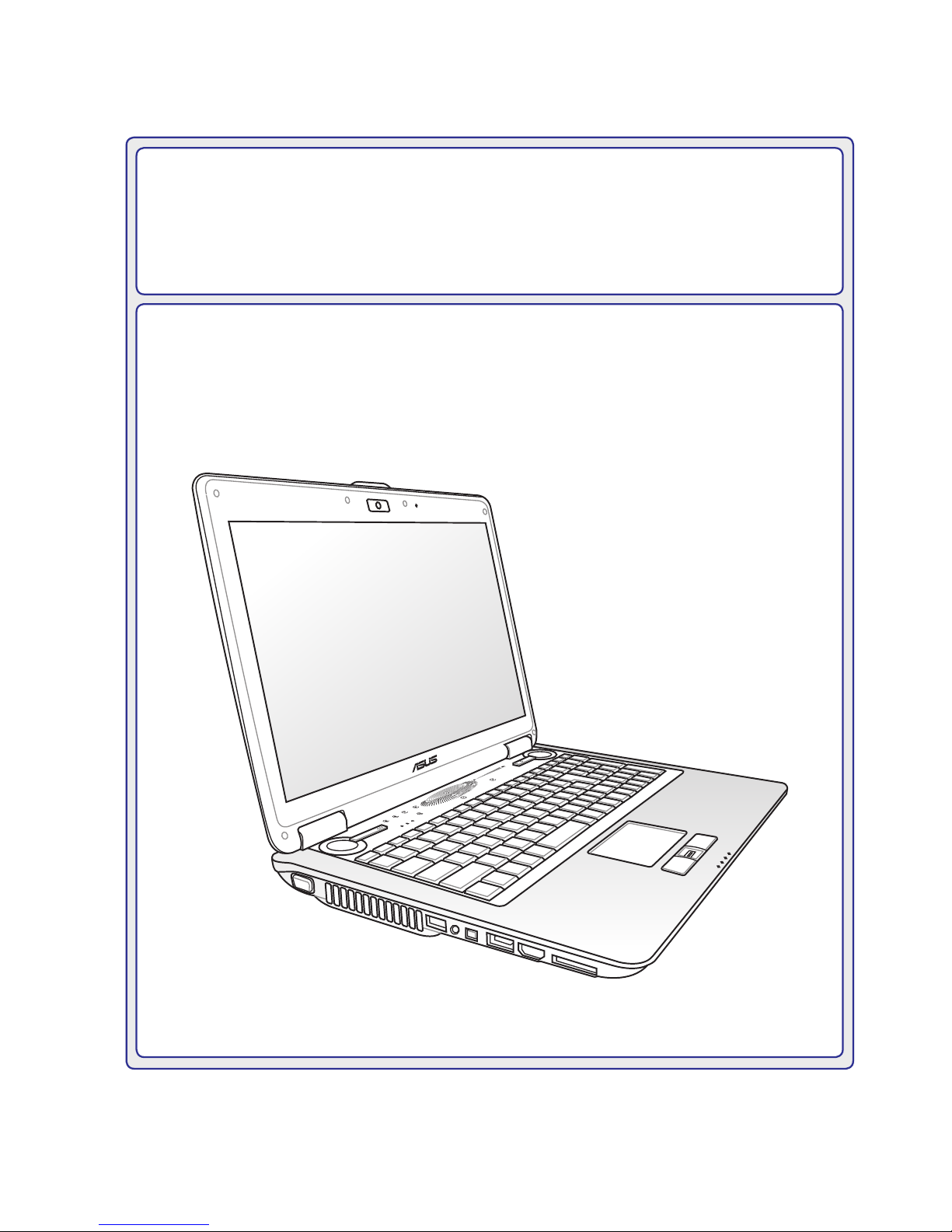
Introducing the Notebook PC 1