7
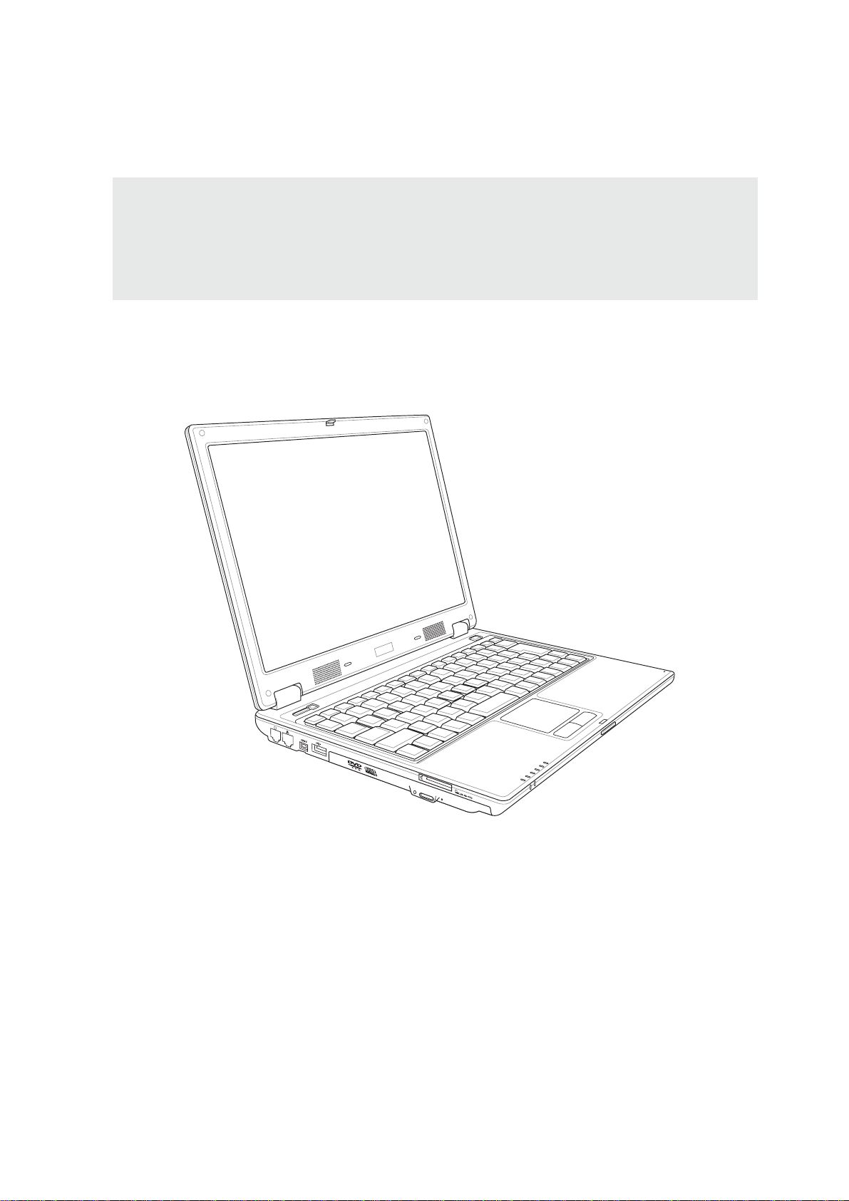
Introducing the Notebook PC 1
Safety Precautions
The following safety precautions will increase the life of the Notebook PC. Follow all precautions and
instructions. Except as described in this manual, refer all servicing to qualified personnel. Do not use
damaged power cords, accessories, or other peripherals. Do not use strong solvents such as thinners,
benzene, or other chemicals on or near the surface.
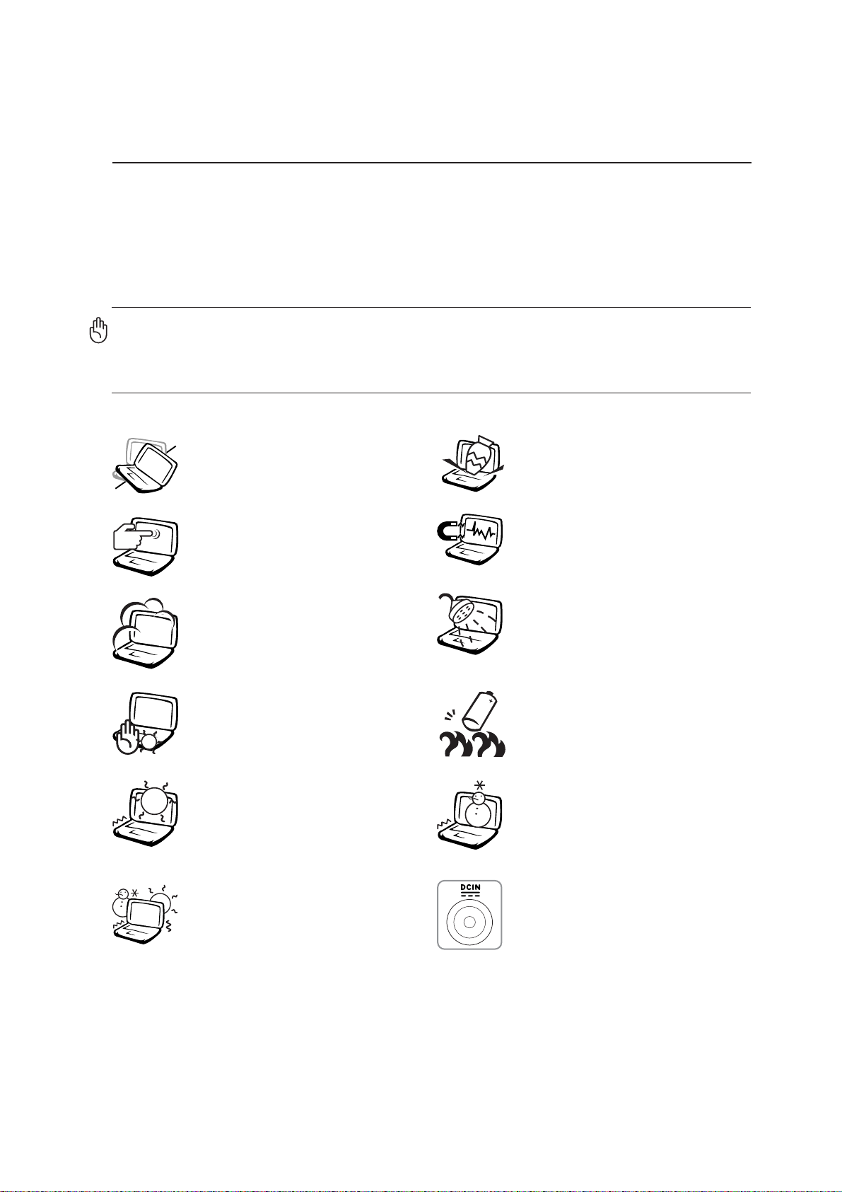
Disconnect the AC power and remove the battery pack(s) before cleaning. Wipe the
Notebook PC using a clean cellulose sponge or chamois cloth dampened with a solu-
tion of nonabrasive detergent and a few drops of warm water and remove any extra
moisture with a dry cloth.
DO NOT expose to or use near liq-
uids, rain, or moisture. DO NOT use
the modem during an electrical storm.
DO NOT expose to dirty or dusty en-
vironments. DO NOT operate during
a gas leak.
DONOTexposetoextremetemperatures
above 50˚C (122˚F) or to direct sunlight.
Do not block the fan vents!
DO NOT throw batteries in fires as
they may explode. Check local codes
for special battery disposal instruc-
tions.
DO NOT expose to extreme tempera-
tures (below 0˚C (32˚F), otherwise the
Notebook PC may not boot.
DO NOT expose to strong magnetic
or electrical fields.
DONOTplace on uneven or unstable
work surfaces. Seek servicing if the
casing has been damaged.
DO NOT place or drop objects on top
and do not shove any foreign objects
into the Notebook PC.
DO NOT press or touch the display
panel. Do not place together with small
itemsthat may scratch orentertheNote-
book PC.
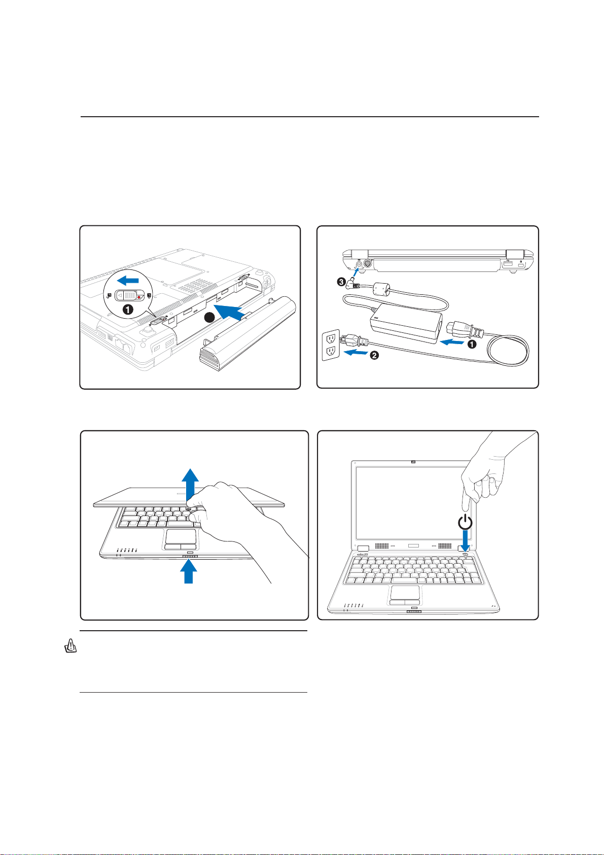
DO NOT leave the Notebook PC on
your lap or any part of the body while
the Notebook PC is turned ON or is
charging in order to prevent discom-
fort or injury from heat exposure.
SAFE TEMP: This notebook PC
should only be used in environments
with ambient temperatures between
0°C (32°F) and 35°C (95°F).
INPUT RATING: Must only receive
power input of 19VDC, 3.42A (65W).