Atag HG9511EBA User manual

Ombouwvoorschrift
Plaatsen service kit wok-brander
Consigne de conversion
Installation du kit de service pour brûleur wok
Conversion instructions
Installation of wok burner service kit
Инструкция по переоборудованию
Установка сервисного комплекта конфорки вок

NL
Ombouwvoorschrift NL 3 - NL 7
FR
Consigne de conversion FR 3 - FR 7
EN
Conversion instruction EN 3 - EN 7
RU
Руководство по переоборудованию RU 3 - RU 7
Gebruikte pictogrammen - Pictogrammes utilisés - Pictograms used - Используемые
пиктограммы
Belangrijk om te weten - Important à savoir - Important information - Важная информация
Tip - Conseil - Совет

NL 3
INHOUD
Inleiding (A)
4
Demonteren (B)
5
Ombouwen (C)
5
Controleren op gasdichtheid en werking (D)
6
Afmonteren
7
In gebruik stellen
7
Werking controleren (E)
7

NL 4
Let op; Het uitvoeren van deze instructie door een niet bevoegd
monteur kan leiden tot gevaarlijke situaties.
De leverancier is niet aansprakelijk voor gevolgen (het ontstaan van
een gevaarlijke situatie en/of schade aan personen en goederen)
ontstaan door het foutief uitvoeren van deze instructie door monteurs
die niet in dienst zijn van de leverancier. Gevolgschade ontstaan door
ondeskundig uitvoeren van deze instructie wordt niet gehonoreerd.
Deze ombouwset bestaat uit originele onderdelen. Originele onderdelen
worden gekeurd op geschiktheid en veiligheid tijdens de typekeuring
van het toestel. Regelmatig uitgevoerde partijkeuringen garanderen de
kwaliteit van originele onderdelen.
De leverancier adviseert het plaatsen van deze service set te laten
uitvoeren door een monteur van de leverancier. Bel de servicedienst
voor het maken van een afspraak met de servicemonteur.
Zie voor de adresgegevens het garantiebewijs van het toestel.
Inleiding (A)
Deze ombouwvoorschrift beschrijft het vervangen van de supervario
wokbranderdelen voor een betere werking.
Gereedschap
A. Dop- of pijpsleutel
B. Sleufkop schroevendraaier
C. Torx schroevendraaier
D. Kruiskop schroevendraaier
E. Puntbektang
F. Steeksleutel
G. lek testspray
OMBOUWVOORSCHRIFT
7
4
T20
P2
7

NL 5
OMBOUWVOORSCHRIFT
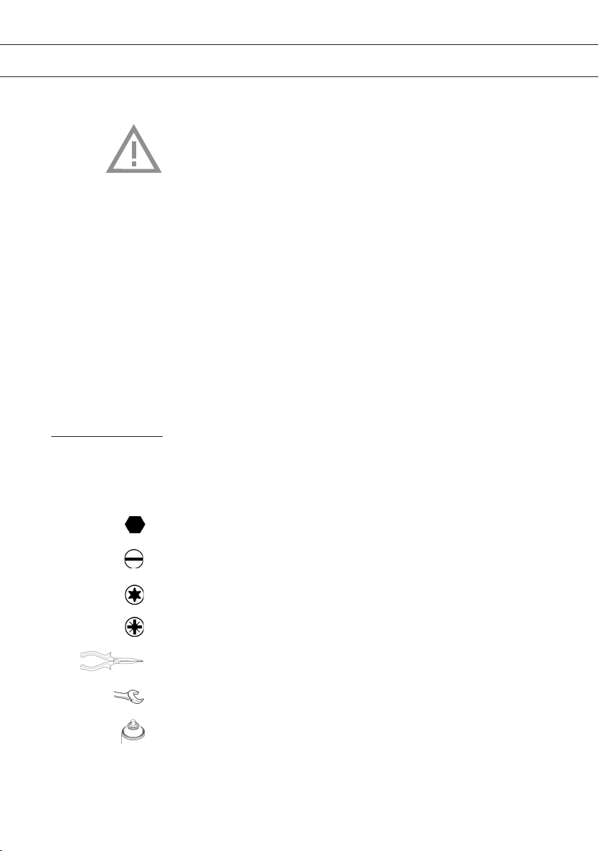
Inhoud van de ombouwset:
• Spuitstuk voor de branderkop Wok en branderkelk Wok (zie
afbeelding A1, achterin deze instructie);
• Spaarstandschroef voor de wokgaskraan;
• Pakkingringen;
• Fiberringen voor geëmailleerde toestellen.
Demonteren (B)
Let op: maak het toestel spanningsloos voordat de vangschaal
verwijderd wordt! Voorkom beschadiging van het werkblad, leg delen
van het toestel op een beschermende ondergrond.
1. Verwijder de pandragers, branderkoppen en branderkelken. Trek de
bedieningsknoppen rechtstandig omhoog en verwijder deze.
2. Gooi de wokbranderkelk en de wokbranderkop weg (afb. B4).
3. Draai de schroeven van de bevestigingsbeugels aan de onderkant
van het toestel los (zie afbeelding B1, achterin deze instructie).
4. Verwijder de schroeven rond de branders (zie afbeelding B2,
achterin deze instructie).
5. Til de vangschaal op aan de achterkant en schuif deze daarna naar
voren. Als er een aardeverbinding aan de vangschaal zit, maak deze
dan los (zie afbeelding B3, achterin deze instructie).
6. Verwijder de vangschaal van het toestel.
Ombouwen (C)
De positie, type brander (hoofdletter) en de kraan (kleine letter) worden
schematisch weergegeven op het etiket in de onderbak.
Let op: geldt alleen voor toestellen aangesloten op G20/20 mbar of
G25/G25.3 25mbar (zie Table 1).
De volgende sets kunnen voorkomen:
• Sets ‘H2’ en ‘h’ voor de wokbrander.

NL 6
OMBOUWVOORSCHRIFT
1. Vervang de spaarstandschroef ‘h’ in de wokkraan.
Gebruik voor demontage/montage van de spaarstandschroef een
schroevendraaier bladbreedte 4 mm (zie afbeelding C2, achterin
deze instructie) en indien nodig een tang.
2. Vervang bij de wokbrander de injector voor de binnenbrander (H2)
met een steeksleutel 7.
Let op! De injector voor de binnenbrander bevind zich bovenin
het branderhuis (zie afbeelding C1, achterin deze instructie).
Controleren op gasdichtheid en werking (D)
Als het toestel is aangesloten op de gastoevoer, controleer het
toestel op gasdichtheid met lek-testspray.
1. Sluit de injector af.
2. Open de gaskraan.
Let op; kranen met een thermische beveiliging indrukken, opendraaien
en ingedrukt houden!
3. Spuit lek-testspray op de verbindingen en controleer deze op
gasdichtheid.
4. Herhaal dit voor elke brander.
Als het toestel niet is aangesloten op de gastoevoer, controleer de
gasdichtheid met een drukpomp.
1. Sluit de drukpomp aan op de gasleiding en sluit alle gaskranen.
2. Verhoog de druk tot 150 mbar en sluit de kraan tussen drukpomp
en drukmeter. Controleer de druk. Het drukverlies mag maximaal
5 mbar per minuut bedragen. Open na controle de kraan tussen
drukpomp en drukmeter.
Let op; kranen met een thermische beveiliging indrukken, opendraaien
en ingedrukt houden!
3. Verhoog de druk tot 150 mbar en sluit opnieuw de kraan tussen
drukpomp en drukmeter. Controleer de druk. Het drukverlies mag
maximaal 5 mbar per minuut bedragen.
4. Herhaal deze test voor alle kranen en injectors.

NL 7
Afmonteren
1. Vervang de pakkingen op de branders.
2. Plaats de vangschaal op het toestel. De haakjes aan de voorkant
van de vangschaal moeten onder de rand van de onderbak worden
geschoven. Vergeet bij geëmailleerde vangschalen niet om de
aardedraad aan te sluiten op de vangschaal.
3. Monteer de schroeven om de vangschaal vast te zetten! Gebruik
nieuwe fiberringen bij geëmailleerde vangschalen.
4. Draai de schroeven van de bevestigingsbeugels aan de onderkant
van het toestel aan.
In gebruik stellen
1. Plaats de nieuw geleverde wokbrander delen. Plaats de
knoppen en overige branderdelen.
2. Controleer of het toestel is aangesloten op de juiste gassoort en
gasdruk.
3. Open de gastoevoer en steek de stekker in het stopcontact.
Werking controleren (E)
1. Ontsteek de branders.
2. Controleer of het vlambeeld over het gehele regelbereik regelmatig en
stabiel is (zie afbeeldingen E1, E2 en E3, achterin deze instructie).
Belangrijk hierbij is dat:
• De vlam niet dooft in kleinstand;
• de brander niet ‘afblaast’ in volstand (te herkennen aan vlammen die
ver van de brander afstaan in combinatie met een ‘sissend’ geluid);
• Er geen lange gele vlammen zichbaar zijn.
OMBOUWVOORSCHRIFT

NL 8

FR 3
SOMMAIRE
Introduction (A)
4
Démontage (B)
5
Conversion (C)
5
Contrôle de l'étanchéité au gaz et du fonctionnement (D)
6
Montage final
7
Mise en service
7
Contrôle du fonctionnement (E)
7

FR 4
Attention : Ces instructions doivent être exécutées par un
technicien qualifié, sous peine de conduire à des situations
dangereuses.
Le fournisseur n’est pas responsable des conséquences (situation
dangereuse et/ou blessures corporelles ou dommages matériels)
résultant du non-respect de ces instructions par des techniciens qui
ne travaillent pas pour lui. Les dommages résultant d’une mauvaise
exécution de ces instructions ne seront pas indemnisés.
Ce kit de conversion est composé de pièces d’origine. L'adéquation
et la sécurité des pièces d'origine sont vérifiées au cours de l’examen
de type de l’appareil. Des contrôles par lot exécutés régulièrement
garantissent la qualité des pièces d’origine.
Le fournisseur recommande de confier l'installation de ce kit à un
technicien du service après-vente. Téléphonez au fournisseur pour
prendre rendez-vous avec un technicien du service.
Consultez le certificat de garantie de l’appareil pour obtenir l’adresse.
Introduction (A)
Cette instruction de modification décrit la procédure de remplacement
des composants du brûleur wok Supervario pour garantir un meilleur
fonctionnement.
Outils
A. Clé à douille ou à pipe
B. Tournevis pour vis à tête fendue
C. Tournevis pour vis Torx
D. Tournevis pour vis cruciformes
E. Pince à bec
F. Clé plate
G. Aérosol pour fuites
CONSIGNE DE CONVERSION
7
4
T20
P2
7

FR 5
CONSIGNE DE CONVERSION
Contenu du kit de conversion:
• Injecteur pour chapeau de brûleur wok et couronne de brûleur wok
(voir l'illustration A1, à la fin de cette notice) ;
• Vis de mode à petit feu pour le robinet de gaz du brûleur wok ;
• Joints d’étanchéité;
• Rondelles en fibre pour appareils émaillés.
Démontage (B)
Attention: débranchez l’appareil du secteur avant de retirer le plan
profond de la table de cuisson! Veillez à ne pas endommager le plan
de travail. Placez les pièces de l’appareil sur une surface protégée.
1. Retirez les supports de casserole, les chapeaux de brûleurs et
les couronnes de brûleurs. Soulevez et retirez les boutons de
commande à la verticale.
2. Jetez la couronne et le chapeau de brûleur wok (ill. B4).
3. Dévissez les supports de montage en dessous de l’appareil (voir
l'illustration B1, à la fin de cette notice).
4. Retirez les vis autour des brûleurs (voir l’illustration B2, à la fin de
cette notice).
5. Soulevez le plan profond à l’arrière et faites-le glisser vers l’avant.
Si une prise de terre est raccordée au plan profond, détachez-la
(voir l’illustration B3, à la fin de cette notice).
6. Retirez le plan profond de l’appareil.
Conversion (C)
L’emplacement, le type de brûleur (lettre majuscule) et le robinet (lettre
minuscule) sont indiqués de manière schématique sur l’étiquette du
bac inférieur.
Attention : ceci ne concerne que les appareils raccordés à G20/20
mbar ou G25/G25.3 25 mbar (voir le Tableau 1).
Les kits suivants sont disponibles:
• Kits «H2» et «h» pour le brûleur wok.

FR 6
CONSIGNE DE CONVERSION
1. Remplacez la vis de mode à petit feu «h» dans le robinet du
brûleur wok.
Pour le démontage/montage de la vis de mode à petit feu, utilisez
un tournevis à lame de 4mm (voir l'illustration C4, à la fin de cette
notice) et, si nécessaire, une pince.
2. Sur le brûleur wok, remplacez l’injecteur du brûleur intérieur (H2)
avec une clé plate7.
Attention! L'injecteur du brûleur intérieur se trouve au-dessus du
logement du brûleur (voir l'illustration C1, à la fin de cette notice).
Contrôle de l'étanchéité au gaz et du fonctionnement (D)
Si l’appareil est raccordé à l’alimentation en gaz, vérifiez
l’étanchéité au gaz à l’aide de l’aérosol pour fuites.
1. Fermez l’injecteur.
2. Ouvrez le robinet de gaz.
Attention : avec des robinets à protection thermique, il faut enfoncer,
tourner pour ouvrir et maintenir enfoncé !
3. Projetez de l'aérosol pour fuites sur les raccords et vérifiez leur
étanchéité au gaz.
4. Répétez cette opération pour chaque brûleur.
Si l’appareil n’est pas raccordé à l’alimentation en gaz, vérifiez
l’étanchéité au gaz avec une pompe de compression.
1. Raccordez la pompe de compression à la conduite de gaz et
fermez tous les robinets de gaz.
2. Augmentez la pression jusqu'à 150mbar et fermez le robinet
entre la pompe de compression et le manomètre. Contrôlez la
pression. La perte de pression ne doit pas dépasser 5mbar par
minute. Après la vérification, ouvrez le robinet entre la pompe de
compression et le manomètre.
Attention : avec des robinets à protection thermique, il faut enfoncer,
tourner pour ouvrir et maintenir enfoncé !

FR 7
3. Augmentez la pression jusqu'à 150mbar et fermez de nouveau le
robinet entre la pompe de compression et le manomètre. Contrôlez
la pression. La perte de pression ne doit pas dépasser 5mbar par
minute.
4. Répétez le test pour tous les robinets et tous les injecteurs.
Montage final
1. Remplacez les joints d’étanchéité sur les brûleurs.
2. Placez le plan profond sur l’appareil. Les crochets situés à l’avant
du plan profond doivent être glissés sous le bord du bac inférieur.
Dans le cas d’un plan profond émaillé, n’oubliez pas de raccorder le
fil de terre au plan profond.
3. Serrez les vis pour fixer le plan profond! Utilisez de nouvelles
rondelles en fibre pour les plans profonds émaillés.
4. Vissez les supports de montage sur le dessous de l’appareil.
Mise en service
1. Placez les nouveaux éléments de brûleur wok. Placez les
boutons et autres éléments de brûleur.
2. Vérifiez que l’appareil est raccordé au type de gaz et à la pression
de gaz appropriés.
3. Ouvrez l’alimentation en gaz et insérez la fiche dans la prise
électrique.
Contrôle du fonctionnement (E)
1. Allumez les brûleurs.
2. Vérifiez que la flamme est régulière et stable sur toute la plage
de réglage (voir les illustrations E1, E2 et E3, à la fin de cette
consigne).
Il est important que:
• la flamme ne s’éteigne pas en position basse ;
• le brûleur ne «siffle» pas en position haute (les flammes brûlent
loin du brûleur et un bruit de sifflement est émis) ;
• toute longue flamme jaune soit exclue.
CONSIGNE DE CONVERSION

FR 8

EN 3
CONTENTS
Introduction (A)
4
Disassembly (B)
5
Conversion (C)
5
Leak test and performance check (D)
6
Reassembly
7
Preparations for use
7
Performance check (E)
7

EN 4
Note: Allowing an unqualified technician to carry out the work
described in these instructions can result in hazardous situations.
The supplier cannot be held liable for the consequences (hazardous
situations and/or injury to persons and/or damage) arising from the
failure of a technician who is not employed by the supplier to follow
these instructions. No compensation will be made for consequential
loss incurred as a result of the failure to follow these instructions.
This conversion set contains original parts. Original parts are tested
during the type approval testing of the appliance to verify that the
parts are suitable for the purpose and are safe. Regular inspections of
batches are carried out to assure the quality of original parts.
The supplier recommends that this service set should be installed by
one of the supplier’s technicians: Contact the service desk to make an
appointment with a service technician.
The address is shown on the appliance's warranty certificate.
Introduction (A)
These conversion instructions explain how to replace the supervario
wok burner parts to improve the burner's performance.
Tools
A. Socket spanner or box spanner
B. Flat-head screwdriver
C. Torx screwdriver
D. Phillips-head screwdriver
E. Needle-nose pliers
F. Open-end spanner
G. Leak-test spray
CONVERSION INSTRUCTIONS
7
4
T20
P2
7

EN 5
CONVERSION INSTRUCTIONS
Contents of the conversion set:
• Injector for the wok burner head and wok burner distributor (see
Figure A1 at the back of these instructions);
• Simmer adjustment screw for the wok gas tap;
• Gaskets;
• Fibre rings for enamelled appliances.
Disassembly (B)
Note: disconnect the appliance from the power supply before removing
the drip tray! Avoid damage to the worktop by laying the parts of the
appliance on a protective surface.
1. Remove the pan supports, burner heads and burner distributors.
Pull the control knobs upwards and remove them.
2. Dispose of the wok burner distributor and wok burner heads (Figure
B4).
3. Loosen the screws of the mounting brackets under the appliance
(see Figure B1 at the back of these instructions).
4. Remove the screws around the burners (see Figure B2 at the back
of these instructions).
5. Lift the back of the drip tray and slide the tray forwards. When an
earth lead is connected to the drip tray, disconnect the lead (see
Figure B3 at the back of these instructions).
6. Remove the drip tray.
Conversion (C)
The position and the type of burner (capital letter) and tap (small letter)
are shown on the label inside the bottom tray.
Note: only applicable to appliances connected to G20/20 mbar or G25/
G25.3 25 mbar gas supplies (see Table 1).
The burner assembly can consist of one of the following sets:
• Sets ‘H2’ and ‘h’ for the wok burner.

EN 6
CONVERSION INSTRUCTIONS
1. Replace simmer adjustment screw ‘h’ in the gas tap.
Use a 4 mm flat-head screwdriver and, if necessary, pliers to
remove the simmer adjustment screw (see Figure C2 at the back of
these instructions) and then fit and tighten the new screw.
2. Replace the wok burner’s inner burner injector (H2) using a 7 mm
open-ended spanner.
Note! The inner burner's injector is the top injector in the burner
body (see Figure C1 at the back of these instructions).
Leak test and performance check (D)
When the appliance is connected to the gas supply: carry out the
leak test using the leak-test spray.
1. Seal the injector.
2. Open the gas tap.
Note: taps fitted with a thermal safeguard must be pressed in, turned
open and kept pressed in!
3. Spray the leak-test spray on the connections and inspect for leaks.
4. Repeat for each burner.
When the appliance is not connected to the gas supply: carry out
the leak test under pressure using an air pump.
1. Connect the pump to the gas pipe and close all gas taps.
2. Increase the pressure to 150 mbar and close the valve between the
pump and pressure gauge. Check the pressure. The pressure may
not fall by more than 5 mbar a minute. After the test, open the valve
between the pump and pressure gauge.
Note: taps fitted with a thermal safeguard must be pressed in, turned
open and kept pressed in!
3. Increase the pressure to 150 mbar and once again close the valve
between the pump and pressure gauge. Check the pressure. The
pressure may not fall by more than 5 mbar a minute.
4. Repeat this test for all taps and injectors.

EN 7
Reassembly
1. Replace the burner gaskets.
2. Fit the drip tray bank onto the appliance. The clips on the front of
the drip tray must be slid under the rim of the bottom tray.
The earth lead of enamelled drip trays must be reconnected to the
drip tray.
3. Fit the screws to fasten the drip tray! With enamelled drip trays, fit
new fibre rings.
4. Tighten the screws of the mounting brackets under the appliance.
Preparations for use
1. Fit the new wok burner parts. Fit the knobs and other burner
parts.
2. Check to verify that the appliance is connected to the correct type
of gas and gas pressure.
3. Open the tap in the gas supply and put the plug in the power
socket.
Performance check (E)
1. Light the burners.
2. Check that the flame is regular and stable over the entire control
range (see figures E1, E2 and E3 at the back of these instructions).
Important:
• The flame must not go out at lower settings;
• The burner must not ‘blow off’ at the full setting (this is the case
when the flames are too far from the burner and a ‘hissing’ sound
can be heard);
• The flames must not be yellow.
CONVERSION INSTRUCTIONS

EN 8
This manual suits for next models
7
Table of contents
Languages:
Other Atag Kitchen Appliance manuals