Atag NEOZ User manual

8X.51.10.01/ 11.18 Changes reserved . Wijzigingen voorbehouden . Modi ications réservée . Änderungen und Irrtümer vorbehalten . Modi icazione riservato.
Installation manual / Installatie handleiding
Manuel d'installation / Installationsanleitung
Manuale di installazione
Cube
GB / NL / F / D / I
ATAG NEOZ
3319471

2 / EN
SAFETY RULES
WARNING!
The following manual is an integral and essential part of the product and must always be kept
with care and attached to the product, even if it is transferred to another owner or user, or
when it is used with a dierent application.
Do not use the product for any purpose other than that specified in this manual. The
manufacturer is not liable for damage resulting from improper use of the product or failure to
install it as instructed herein. All maintenance on the product must be carried out exclusively
by qualified sta using solely original spare parts. The manufacturer is not liable for damage
resulting from failure to observe this instruction, which may compromise the safety of the
installation.
WARNING!
The appliance can be used by children older than 8 years and by people with reduced
physical, sensory or mental abilities, or who lack adequate experience and the necessary
knowledge, provided that they are supervised or have been instructed on how to use the
appliance safely and on understanding the attendant risks.
Children must not play with the appliance. Any cleaning and maintenance which should be
performed by the user must not be done by unsupervised children.
OVERVIEW
The ATAG NEOZ system interface oers simple and ecient room temperature
adjustment and domestic hot water control.

EN / 3
SYMBOL LEGEND:
Failure to comply with this warning entails the risk of injury to persons, which in some
circumstances may be fatal.
Failure to comply with this warning may result in serious damage to property and plants
or injury to animals.
The manufacturer is not liable for damage resulting from improper use of the product or
failure to install it as instructed herein.
Do not perform operations that involve removing the appliance from its installation
location.
Damage to the device.
Do not climb onto chairs, stools, ladders or unstable supports to clean the device.
Personal injury caused by falling from a height or shearing (stepladders shutting
accidentally).
Do not use any insecticides, solvents or aggressive detergents to clean the appliance.
Damage to plastic or painted parts.
Do not use the appliance for any purpose other than normal domestic use.
Damage to the device caused by operation overload.
Damage to objects caused by improper use.
Do not allow children or inexperienced people to operate the appliance.
Damage to the appliance due to improper use.
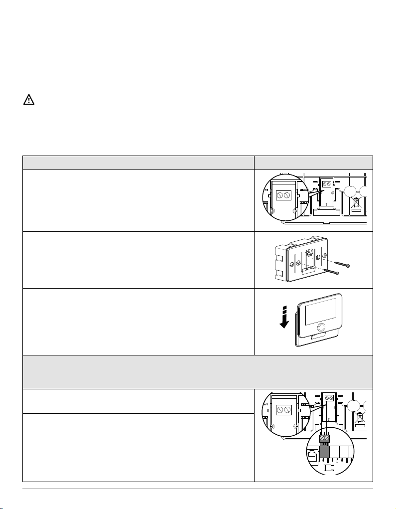
During the cleaning, maintenance and connection operations, it is necessary to
isolate the appliance from the mains supply by removing the plug from the socket.
Personal injury due to electrocution.
PRODUCT IN COMPLIANCE WITH EU DIRECTIVE 2012/19/EU
The barred wheeled bin symbol appearing on the appliance or on its packaging indicates that the
product must be collected separately from other waste at the end of its useful life.
The user must therefore deliver the decommissioned product to an appropriate local facility for
separate collection of electrotechnical and electronic waste. Alternatively, the appliance to be
scrapped can be delivered to the dealer when purchasing a new equivalent appliance. Electronic
products for disposal measuring less than 25 cm can also be delivered free of charge to electronic
equipment dealers having a surface area of at least 400 m2, without having to purchase other
products. Proper separated collection of the decommissioned appliance for its subsequent recycling,
treatment and eco-compatible disposal helps to prevent negative eects on the environment and
human health, besides encouraging reuse and/or recycling of its constituent materials.

4 / EN
TECHNICAL DATA
Dimensions 134 mm x 96 mm x 21 mm
Power supply ATAG Zone BUS 8 to 24V max
Current draw ≤35mA
Operating temperature -0 ÷ 50°C
Storage temperature -10 ÷ 45°C
Humidity 20% RH ÷ 80% RH
Temperature reading precision +/- 0,5°C
Buer memory duration min 2h
Bus cable length and cross-sectional area max. 50 m ø min. 0.5 mm²
NOTE: IN ORDER TO AVOID INTERFERENCE PROBLEMS, USE A SHIELDED CABLE OR TWISTED
PAIR CABLE.
PRODUCT TECHNICAL SHEET
Supplier name ATAG
Supplier identification model ATAG NEOZ
Temperature control class V
Energy eciency contribution (%) for space heating
+3%
Addition of an ATAG External Sensor:
Temperature control class
VI
Energy eciency contribution (%) for space heating
+4%
In a system with 3 zones with 2 ATAG Room Sensors:
Temperature control class
VIII
Energy eciency contribution (%) for space heating
+5%
PRODUCT DESCRIPTION
134 mm17.8 mm
95.6 mm

EN / 5
INSTALLING THE PRODUCT
The device detects the room temperature, therefore several factors should be taken into
account when choosing an installation site. Position the device far from heat sources (radiators,
sunlight, fireplaces, etc.) and from draughts, doorways and windows which could aect the
temperature readings. It should be installed approximately 1.5 metres above the floor level.
WARNING!
Installation should be performed by a qualified technician.
Before making any connections, shut o the electricity power supply to the heat
generator via its external two-position switch. Install the product in a room with a normal
level of pollution.
WALL INSTALLATION
Connect the pair of wires to the terminal block to connect
to the heat generator via BUS
B T
BUS
B T
Fix the base plate contained in the installation kit to the
wall
Position the ATAG NEOZ onto the base plate and push it
delicately downwards.
CONNECTION TO THE SYSTEM
The sending, receiving and decoding of signals occurs through the BridgeNet® BUS
protocol, which puts the heat generator and the system interface into contact with each other
Connect a pair of wires to the BUS connector on the heat
generator P.C.B.
B T
BUS
B T
BUS
T B
The electrical connection of the device is not polarised.
NOTE: IN ORDER TO AVOID INTERFERENCE PROBLEMS, USE A
SHIELDED CABLE OR TWISTED PAIR CABLE.
NOTE 2: Connect only one system interface to the BUS network

6 / EN
INITIAL CONFIGURATION
CONFIGURATION PROCEDURE
Initialisation
Insert the system interface into the connection shoe by pushing it gently
downwards and making sure that the products are powered; after a brief
initialisation, the device will be ready to be configured.
Selecting the
language
The display screen shows “Language”. Select the language by rotating the
knob. Press OK to confirm
Selecting date and
time
The display shows the “Time & Date”. Turn the knob to select day, month and
year. For each selection, press the knob to confirm.
Once the date is set, the selection moves to setting the time.
Turn the knob to set the correct time; for each selection, press the knob to
confirm.
Selecting the mode
daylight saving time
Once the date is set, the selection moves to the daylight saving time setting.
Turn the knob to select TIME PROGRAM or MANUAL.
If you want the system to automatically update the period when daylight sav-
ing time is in use, select TIME PROGRAM. Press the knob to confirm.
Selecting the zones
“Zones” Menu
This screen is used to select the hydraulic zones to be displayed in the
“Zones” user menu. Turn the knob to select the zones in the system and
press the knob to confirm.
Setting the “Zone”
parameters
For devices compatible with this function, you can set the following param-
eters for the selected Zone:
- Operating mode: Manual/Programmed/O;
- Zone Name (only for compatible devices);
- Room temperature Setpoint;
- Heating Controller (only for compatible devices)
set the type of device associated with the zone being heated:
• none
• room sensor
• thermostat;
- Cooling Controller (only for compatible devices)
set the type of device associated with the zone being cooled:
• none
• room sensor
• thermostat;
WARNING!
To guarantee safety and correct operation of the system interface, it must be
commissioned by a qualified technician in possession of the skills as required by law.

EN / 7
Selecting the zone
After, the display screen shows the selection of the zone to be assigned to
the room temperature control device.
Turn the knob to select the desired zone. Press the knob to confirm. By as-
signing zone no. 0 the device will exclusively carry out the function of system
interface. After the zone selection, the system will repeat the initialisation
procedure
WARNING!
BUS ADDRESSING CONFLICT
After initialisation, if the zone assigned to the device is already being used by anoth-
er device on the BUS network, an addressing conflict error message will be displayed.
Press the knob to access the configuration page of the BridgeNet Bus network. Proceed
with the correct addressing of the devices according to the instructions in the respective
manuals.
WARNING!
TIME SCHEDULING CONFLICT
A time scheduling conflict error is generated when one of the programmable devices on
the network does not support multi-level programming.
In this case, the programming must be set on “2 levels” through the 0.4.3. parameter.
WARNING!
ROOM TEMPERATURE CORRECTION
In the event of installation on a wall-mounted Remote Modem (Light Gateway), the room
temperature measurement may require a correction.

8 / EN
START SCREEN
A. Menu button
B. Knob
(turn to select /
press to confirm)
C. Esc button (back)
D. Function Icons
E. Weather and Outdoor temperature
F. Room temperature
G. Desired temperature
H. Date and Time
I. Operation icons
L. Pressure indication
Wi-Fi module update in progress
AP
Access Point Opening in progress
Wi-Fi O or not connected
Wi-Fi connected but internet access failed
Wi-Fi active
Outdoor temperature
Flame present
Optimum boiler eciency
Solar heating module connected
Photovoltaic contact enabled
Photovoltaic contact active
SG
Smart Grid system enabled
Supplementary heating elements not
enabled
Number of heating element stages active
Heat pump active
Room set-point extension active
Heating
Heating active
Domestic hot water
Domestic hot water active
Cooling service enabled
Cooling service active
90%
Relative humidity index
Programmed
Manual
SCI
Temperature regulation function active
Holiday function active
Domestic hot water Boost function
enabled
Hot water comfort enabled in electricity
reduced band rate
HC 40
Hot water comfort enabled in electricity
reduced band rate and domestic hot
water set-point at 40°C in electricity full
band rate
Test mode active
Thermal sanitation function active
Anti-frost function active
Dehumidification function active
Silent mode active
(only for heat pumps)
Error in progress
30
21°
LIVING ROOM
,5
°C
5
18
,0
°
18:30 11/03/2021
10°
1,5 bar
50%
E HGF
C AB
D I
L

EN / 9
BASIC FUNCTIONS
Room temperature regulation in Manual
mode
The operating mode of the zone associated
with the device is set to “ ” MANUAL.
Turn the knob to select the temperature value
indicated on the display using the movable
cursor close to the ring.
Press the knob to confirm.
The display shows the set temperature.
Room temperature adjustment in
Programmed mode
The operating mode of the zone associated
with the device is set to “ ” PROGRAMMED.
During operation in scheduled programming
mode, the set room temperature can be
changed temporarily. Turn the knob to select
the temperature value indicated using the
movable cursor close to the ring.
Press the knob to confirm.
The display shows the set temperature.
Turn the knob to set the time at which you
want the change to end.
Press the knob to confirm. The “ ” symbol
appears on the display.
The system interface will maintain the tem-
perature value until the set time, after which
the pre-set room temperature is restored.
30
21°
SALOTTO
,5
°C
5
19
,0
°
18:30 11/10/2020
10°
1,5 bar
50%
Fino alle 20:00
30
21°
SALOTTO
,5
°C
5
19
,0
°
18:30 11/10/2020
10°
1,5 bar
50%
Room temperature adjustment with SCI on.
If the heating (or cooling) hot water temperature does not match the desired value, it can be
increased or decreased via the “Heating Settings” (or Cooling settings). The correction bar
will appear on the display. Press the knob to confirm, or press the back button to return to
the previous screen without saving.

10 / EN
USER MENU
Press the Menu button; the display will show
the user menu consisting of two pages.
To enter the second page, turn the knob and
scroll down to the last icon of the first page.
• Zones
Allows you to check the main information on
the operating status of the zones and to set
the operating mode of the single zone.
• Time scheduling
This allows you to set the time scheduling
for heating, cooling, hot water and buer (if
present).
Choose the operating type:
• Energy Consumption
Shows the estimated energy consumption
(gas and electricity) and their performance
over time for the heating, cooling and do-
mestic hot water modes.
• Holiday function
The holiday function disables heating dur-
ing the holiday period and activates the
anti-frost protection for the room heating
system and the DHW storage tank until the
set date.
• Operating mode
Selects the system operating mode:
SUMMER
domestic hot water produced, heating
o.
WINTER
domestic hot water produced, heating
on.
HEATING ONLY
excluding cylinder heating
(if present).
COOLING AND DOMESTIC HOT
WATER
(if present)
COOLING ONLY
excluding cylinder heating
(if present)
OFF
system o, anti-frost function enabled.

EN / 11
• Domestic Hot Water settings
Allows you to select the desired temperature,
the operating mode for hot water production
and the thermal sanitisation function of a
DHW tank (if present).
• Impostazioni Fireplace
When the function is activated, it regulates
the request for heat in the zone associated
with the device based on the external tem-
perature until the selected time. When the
function is active, the indoor temperature
of the room does not aect the request for
heat.
In order to enable the function, there needs
to be an external temperature probe in the
system or, if available, the internet weather
report needs to be active (see Connectivity
menu).
• Connectivity
Allows you to enter the settings of the remote
connection service when a WiFi device
is connected to the bus and allows you to
consult the main diagnostics information.
• System Information
Allows you to consult the main diagnostics
information (of the connected devices), and
the energy eciency performance of the
system.
• Screen Settings
Allows you to configure the main display set-
tings.
•
Advanced Settings
Allows you to access the following functions:
- Heating Temperature Regulation
- Cooling Temperature Regulation
- Buer Settings
- Advanced settings of the connected de-
vices (boiler, heat pump, hybrid...)
- Units of Measurement
- Photovoltaic integration
- Setting the units of measurement
- Measured temperature correction
- Selecting the zones to be displayed in the
“Zone” menu

12 / EN
TECHNICAL AREA
WARNING!
To guarantee safety and correct operation of the system interface, it must be
commissioned by a qualified technician in possession of the skills as required by law.
To enter the technical area simultaneously press the “Esc” and “Menu” buttons until “Enter
code” appears on the display.
Turn the knob and insert the technical code (007) and press to confirm.
Technical area
Language Language setting
Time & Date Date & Time setting
BridgeNet Bus network
setting
Show the connected devices and their features
Zone mode Zone control advanced settings
Complete Menu Access to all menus and technical parameters enabled according to the
connected devices and available zones
Guided procedures Dedicated menu for guided procedures
for setting the devices included in the system
Service Quick access to the service parameters for the technician
Faults
List of the last 10 detected errors
IMPORTANT!:
For more details on the setting of the parameters and procedures of the technical area
please refer to the installation manual of the single products (boilers, heat pumps and
hybrid systems, etc.).
Compliance
EMC: 2014/30/EU
RED: 2014/53/EU
ROHS: 2015/863/EU
Standard
EMC: EN 55014-1:2017; EN 55014-2:2015; CISPR 14-1:2016; CISPR 14-2:2015
RED: ETSI EN 300 328: v2.2.2; ETSI EN 301 489-1: v2.2.3; ETSI EN 301 489-17: v3.2.2;
EN 62311:2008; EN 62368-1:2014+A11:2017
ROHS: EN 50581
Compliance
EEMC: Electromagnetic Compatibility Regulations 2016
RED: Radio Equipment Regulations 2017
ROHS: Restriction of the Use of Certain Hazardous Substances in Electrical and
Electronic Equipment Regulations 2012
Standard
EMC: BS EN 55014-1:2017; BS EN 55014-2:2015; CISPR 14-1:2016; CISPR 14-2:2015
RED: ETSI EN 300 328: v2.2.2; ETSI EN 301 489-1: v2.2.3; ETSI EN 301 489-17: v3.2.2;
BS EN 62311:2008; BS EN 62368-1:2014+A11:2017
ROHS: BS EN 50581

NL / 13
VEILIGHEIDSVOORSCHRIFTEN
LET OP!
Deze handleiding vormt een integraal en essentieel onderdeel van het product en moet daar-
om zorgvuldig worden bewaard en steeds bij het product blijven, ook bij overdracht aan een
andere eigenaar of gebruiker of bij gebruik in een andere toepassing.
Het product mag niet worden gebruikt voor andere dan de in deze handleiding vermelde
doeleinden. De fabrikant kan niet verantwoordelijk worden gesteld voor eventuele schade
die veroorzaakt wordt door ondeskundig gebruik of het niet in overeenstemming met de in
deze handleiding verstrekte instructies uitvoeren van de installatie. Alle onderhoudswerk-
zaamheden aan het product mogen uitsluitend worden uitgevoerd door gekwalificeerd per-
soneel en daarbij mogen alleen originele reserveonderdelen worden gebruikt. De fabrikant
kan niet verantwoordelijk worden gesteld voor mogelijke schade veroorzaakt als gevolg
van de niet-naleving van deze aanwijzingen, wat de veiligheid van de installatie in gevaar
zou kunnen brengen.
LET OP!
Het apparaat mag niet worden gebruikt door kinderen van jonger dan 8 jaar en door per-
sonen met lichamelijke, zintuiglijke of geestelijke beperkingen of personen die niet over de
nodige ervaring en kennis daartoe beschikken, tenzij ze onder toezicht staan of nadat ze de
nodige instructies hebben gekregen voor het veilig gebruik van het apparaat en de gevaren
die ermee gepaard gaan begrijpen.
Kinderen mogen niet met het apparaat spelen. De reiniging en het onderhoud die ten laste
zijn van de gebruiker, mogen niet worden uitgevoerd door kinderen waarop geen toezicht
gehouden wordt.
ALGEMEEN
Met de systeeminterface ATAG NEOZ kunt u de temperatuurregeling van de kamers en
de controle van het warme tapwater eenvoudig en doeltreend beheren.

14 / NL
LEGENDA VAN DE SYMBOLEN:
Het niet in acht nemen van deze waarschuwing kan leiden tot verwondingen van perso-
nen die, in bepaalde gevallen, zelfs dodelijk kunnen zijn.
Het niet in acht nemen van deze waarschuwing kan leiden tot schade, in bepaalde ge-
vallen zelfs ernstige schade aan voorwerpen, planten of dieren.
De fabrikant kan niet verantwoordelijk gesteld worden voor eventuele schade die ver-
oorzaakt wordt door ondeskundig gebruik of het niet in overeenstemming met de in
deze handleiding verstrekte installatie-instructies uitvoeren van de installatie.
Voer geen handelingen uit waarbij u het apparaat van zijn plaats moet halen.
Beschadiging van het apparaat.
Klim niet op stoelen, krukken, trappen of andere instabiele voorwerpen om het appa-
raat te reinigen.
Persoonlijk letsel door het naar beneden vallen of door beklemming (bij een vouwtrap).
Gebruik geen insecticiden, oplosmiddelen of agressieve schoonmaakmiddelen om
het apparaat te reinigen.
Beschadiging van plastic of gelakte onderdelen.
Gebruik het apparaat niet voor andere doeleinden dan voor een normaal huishoude-
lijk gebruik.
Beschadiging van het apparaat door overbelasting.
Beschadiging van verkeerd gebruikte voorwerpen.
Laat het apparaat niet gebruiken door kinderen of personen zonder kennis of ervaring.
Beschadiging van het apparaat door onjuist gebruik.
Tijdens reinigings-, onderhouds- en aansluitingswerken moet het apparaat van het
stroomnet worden afgekoppeld door de stekker uit het stopcontact te trekken.
Persoonlijk letsel door elektrische schokken.
DIT PRODUCT IS IN OVEREENSTEMMING MET DE EU-RICHTLIJN 2012/19/EU
Het symbool van de doorgekruiste vuilnisbak aangebracht op de apparatuur of op de verpakking geeft aan
dat het product aan het einde van zijn nuttige levensduur gescheiden van het andere afval moet worden
ingezameld.
De gebruiker moet de afgedankte apparatuur dus afgeven bij een geschikt gemeentelijk inzamelcentrum
van elektrotechnische en elektronische apparatuur. In plaats van het zelfstandige beheer is het ook mogelijk
de af te danken apparatuur bij de dealer te brengen op het moment van aanschaf van een ander, verge-
lijkbaar apparaat. Bij dealers van elektronische producten met een verkoopoppervlak van ten minste 400
m2 is het verder mogelijk om kosteloos, zonder enige verplichting tot aanschaf, afgedankte elektronische
producten in te leveren met afmetingen van minder dan 25 cm. Een goede gescheiden afvalverwerking en
daaropvolgend doorsturen van de afgedankte apparatuur voor milieuvriendelijke recycling, behandeling en
verwerking dragen ertoe bij om mogelijke negatieve gevolgen voor het milieu en de gezondheid te voor-
komen en bevorderen het hergebruik en/of de recycling van de materialen waaruit de apparatuur bestaat.

NL / 15
TECHNISCHE GEGEVENS
Afmetingen 134 mm x 96 mm x 21 mm
Elektrische voeding ATAG Zone BUS 8 tot 24V max
Stroomopname ≤35mA
Bedrijfstemperatuur -0 ÷ 50°C
Opslagtemperatuur -10 ÷ 45°C
Vochtigheid 20% RV ÷ 80% RV
Nauwkeurigheid temperatuur +/- 0,5°C
Duur buergeheugen min. 2 uur
Lengte en diameter buskabel max. 50 m ø min. 0,5 mm²
OPMERKING: OM INTERFERENTIEPROBLEMEN TE VOORKOMEN DIENT U EEN AFGESCHERMDE
KABEL OF EEN GETWIST PAAR TE GEBRUIKEN.
PRODUCTINFORMATIEBLAD
Naam van de leverancier ATAG
Identificatiemodel van de leverancier ATAG NEOZ
Temperatuurregelingsklasse V
Bijdrage aan de energie-eciëntie % voor de verwarming van ruimtes
+3%
Bij toepassing van een ATAG buitenvoeler
Temperatuurregelingsklasse
VI
Bijdrage aan de energie-eciëntie % voor de verwarming van ruimtes
+4%
In een systeem met 3 zones met 2 ATAG zonethermostaten
Temperatuurregelingsklasse
VIII
Bijdrage aan de energie-eciëntie % voor de verwarming van ruimtes
+5%
PRODUCTBESCHRIJVING
134 mm17,8 mm
95,6 mm

16 / NL
INSTALLATIE VAN HET PRODUCT
Het apparaat neemt de kamertemperatuur waar. Daarom dient u bij het kiezen van een installa-
tieplaats met enkele aspecten rekening te houden. Plaats het apparaat uit de buurt van warm-
tebronnen (verwarmingselementen, zonnestralen, open haard enz.) en uit de tocht of uit de
buurt van openingen naar buiten toe, omdat deze de waarneming van de temperatuur kunnen
beïnvloeden. Het apparaat moet op ca. 1,50 m hoogte vanaf de vloer worden geïnstalleerd.
LET OP!
De installatie moet door gekwalificeerd technisch personeel worden uitgevoerd.
Voordat u een elektrische aansluiting tot stand brengt, dient u de netvoeding naar de
warmtegenerator uit te schakelen. Installeer het product in een omgeving met normale
vervuilingsniveaus.
INSTALLATIE AAN DE WAND
Sluit het draadpaar aan op de klem om de aansluiting van de
warmtegenerator uit te voeren via BUS.
B T
BUS
B T
Bevestig de meegeleverde basisplaat in de installatiekit aan de
muur.
Plaats de ATAG NEOZ op de basisplaat door hem
voorzichtig omlaag te duwen.
AANSLUITING OP HET SYSTEEM
Het verzenden, ontvangen en decoderen van de signalen vindt plaats via het protocol ATAG Zone
BUS, waarmee de warmtegenerator en de systeeminterface met elkaar communiceren.
Sluit een draadpaar aan op de BUS-stekker op de kaart van de
warmtegenerator
B T
BUS
B T
BUS
T B
De elektrische aansluiting van het apparaat is niet gepolariseerd.
OPMERKING: OM INTERFERENTIEPROBLEMEN TE VOORKOMEN DIENT
U EEN AFGESCHERMDE KABEL OF EEN GETWIST PAAR TE GEBRUIKEN.
OPMERKING 2: Sluit slechts één systeeminterface aan op het
BUS-netwerk.

NL / 17
EERSTE CONFIGURATIE
LET OP!
Om de veiligheid en de juiste werking van de systeeminterface te kunnen garande-
ren, moet de inbedrijfstelling worden uitgevoerd door een bevoegde monteur, die een
door de wet erkende kwalificatie bezit.
CONFIGURATIEPROCEDURE
Initialisatie
Plaats de systeeminterface in de aansluitsleuf door hem voorzichtig omlaag
te duwen. Controleer of de producten stroom ontvangen. Na een korte ini-
tialisatie is het apparaat gereed voor de configuratie.
Selectie taal
Op het display verschijnt “Taal”. Selecteer de gewenste taal door aan de
knop te draaien. Druk op de toets OK om te bevestigen.
Selectie
datum en tijd
Op het display verschijnt “Tijd & Datum”. Draai aan de knop om de dag, de maand
en het jaar te selecteren. Druk na elke selectie op de knop om te bevestigen.
Als de datum is ingesteld, gaat de selectie verder naar de instelling van de tijd.
Draai aan de knop om de precieze tijd in te stellen, druk na elke selectie op
de knop om te bevestigen.
Selectie
zomertijd
Als de tijd is ingesteld, gaat de selectie verder naar de instelling van de zo-
mertijd. Draai aan de knop om CV PROGRAMMEERBAAR of CV MANUEEL
te selecteren.
Als u wilt dat het systeem automatisch overgaat op de zomertijd, selecteer
dan CV PROGRAMMEERBAAR. Druk op de knop om te bevestigen.
Selectie van zones
Menu “Zone”
Op dit scherm worden de hydraulische zones geselecteerd die weerge-
geven moeten worden in het gebruikersmenu “Zone”. Draai aan de knop
om de zones te selecteren die aanwezig zijn in de installatie en druk op de
knop om te bevestigen.
Instelling parame-
ters “Zone”
Bij compatibele apparaten kunnen met deze functie voor elke geselecteer-
de zone de volgende parameters worden ingesteld:
- Werkingsmodus: Handmatig/Geprogrammeerd/O;
- Naam zone (alleen voor compatibele apparaten);
- Temperatuur setpoint kamer;
- Regelaar verwarming (alleen voor compatibele apparaten)
Stel het type apparaat in dat gekoppeld is aan de zone die verwarmd
moet worden:
• geen
• kamersensor
• thermostaat;
- Regelaar koeling (alleen voor compatibele apparaten)
Stel het type apparaat in dat gekoppeld is aan de zone die gekoeld moet
worden:
• geen
• kamersensor
• thermostaat;

18 / NL
Selectie zone
Vervolgens verschijnt op het display de selectie van de zone die toegekend
moet worden aan het apparaat voor het regelen van de kamertemperatuur.
Draai aan de knop om de gewenste zone te selecteren. Druk op de knop
om te bevestigen. Door zone nr. 0 toe te kennen voert het apparaat uitslui-
tend de functie van systeeminterface uit. Na het selecteren van de zone
herhaalt het systeem de initialisatieprocedure
LET OP!
CONFLICT BUS-ADRESSERING
Als de aan het apparaat toegewezen zone na de initialisatie al gebruikt wordt door
een ander apparaat in het bus-netwerk, dan verschijnt er de foutmelding ‘conflict
adressering’. Druk op de knop om de configuratiepagina van het ATAG Zone BUS-netwerk
te openen. Voer de correcte adressering van de apparaten uit volgens de instructies in
de betreende handleidingen.
LET OP!
CONFLICT TYPE TIJDPROGRAMMERING
De foutmelding ‘conflict tijdprogrammering’ wordt gegeven wanneer een van de
programmeerbare apparaten in het netwerk geen programmering op meerdere niveaus
ondersteunt.
In dat geval moet de programmering worden ingesteld op “standaard” door middel van
parameter 0.4.3.
LET OP!
CORRECTIE KAMERTEMPERATUUR
Als er een modem met afstandsbediening aan de muur is geïnstalleerd (Light Gateway),
dan moet de kamertemperatuur mogelijk worden gecorrigeerd.

NL / 19
HOOFDSCHERM
30
21°
LIVING ROOM
,5
°C
5
18
,0
°
18:30 11/03/2021
10°
1,5 bar
50%
E HGF
C AB
D I
L
A. Menutoets
B. Draai-druk-knop
(draaien om te selecteren /
drukken om te bevestigen)
C. Esc-toets (terug)
D. Functiesymbolen
E. Weer en buitentemperatuur
F. Kamertemperatuur
G. Gewenste temperatuur
H. Datum en tijd
I. Werkingssymbolen
L. Systeemdruk
Wifi-module wordt bijgewerkt
AP
Access Point wordt geopend
Wifi uitgeschakeld of niet verbonden
Wifi verbonden maar geen
internettoegang
Wifi actief
Buitentemperatuur
Aanwezigheid vlam
Optimale eciëntie ketel
Zonnepaneelmodule aangesloten
Fotovoltaïsche service beschikbaar
Fotovoltaïsch contact actief
SG
Smart Grid-systeem ingeschakeld
Integratieverwarmingselementen niet
ingeschakeld
Aantal stadia actieve
verwarmingselementen
Warmtepomp actief
Uitbreiding setpoint kamer actief
Verwarming
Verwarming actief
Tapwater
Tapwater actief
Koeling beschikbaar
Koeling actief
90%
Indicatie relatieve luchtvochtigheid
Klokprogramma
Handmatig
SCI
Functie temperatuurregeling actief
Functie vakantie actief
Boost-functie tapwater actief
Comfort tapwater ingeschakeld in peri-
ode met gereduceerd stroomtarief
HC 40
Comfort tapwater ingeschakeld in perio-
de met gereduceerd stroomtarief en set-
point warm tapwater op 40°C in tijdzone
met vol stroomtarief
Manuele modus actief
Functie anti-legionella actief
Functie vorstbeveiliging actief
Functie ontvochtiging actief
Stille modus actief
(alleen bij verwarmingspompen)
Foutmelding

20 / NL
BASISFUNCTIES
Regeling kamertemperatuur in de hand-
matige modus
De werkingsmodus van de zone die gekop-
peld is aan het apparaat wordt ingesteld in
“ ” HANDMATIG.
Draai aan de knop om de temperatuur te se-
lecteren, die aangegeven wordt op het dis-
play door de beweegbare cursor op de ring.
Druk op de knop om te bevestigen.
Op het display wordt de ingestelde tempera-
tuur weergegeven.
Regeling kamertemperatuur in de gepro-
grammeerde modus
De werkingsmodus van de zone die gekop-
peld is aan het apparaat wordt ingesteld in
“ ” GEPROGRAMMEERD. Tijdens de wer-
king van de tijdsprogrammering is het mo-
gelijk om de ingestelde kamertemperatuur
tijdelijk te wijzigen. Draai aan de knop om de
temperatuur te selecteren, die aangegeven
wordt op het display door de beweegbare
cursor op de ring.
Druk op de knop om te bevestigen.
Op het display wordt de ingestelde tempera-
tuur weergegeven.
Draai aan de knop om de tijd in te stellen tot
wanneer u de wijziging wilt vasthouden.
Druk op de knop om te bevestigen. Op het
display verschijnt het symbool “ ”
30
21°
LIVING ROOM
,5
°C
5
19
,0
°
18:30 11/03/2021
10°
1,5 bar
50%
Setpoint override active until: 21:00
30
21°
LIVING ROOM
,5
°C
5
19
,0
°
18:30 11/03/2021
10°
1,5 bar
50%
De interface van het systeem handhaaft de temperatuurwaarde tot aan de ingestelde tijd,
waarna deze terugkeert tot de vooraf ingestelde kamertemperatuur.
Regeling kamertemperatuur met SCI-functie actief.
Als de temperatuur van het warme water voor verwarming (of koeling) niet overeenkomt
met de gewenste temperatuur, dan kan deze verhoogd of verlaagd worden via “Instellingen
verwarming” (of Instellingen koeling). Op het display wordt de correctiebalk weergegeven.
Druk op de knop om te bevestigen of op de terug-toets om terug te keren naar het vorige
scherm, zonder de gegevens op te slaan.
This manual suits for next models
1
Table of contents
Languages:
Other Atag Thermostat manuals
Popular Thermostat manuals by other brands

Aube Technologies
Aube Technologies TH115 A owner's guide

Aube Technologies
Aube Technologies TH141-HC-28 user guide

meitav-tec
meitav-tec ETN24-PM-HP-SUPER-BL Owner's manual & technician settings

Seitron
Seitron TFA01M manual

OJ Electronics
OJ Electronics MSD4-1999-UA instructions

nest
nest T3007ES Welcome guide

Carrier
Carrier Aquazone 50QE900 owner's manual

Amana
Amana 2246002 Installation, operation & application guide

Dornbracht
Dornbracht Xtool 35 524 970 90 installation instructions

Venstar
Venstar ColorTouch T8800 Owner's manual & installation guide

NOBOCOOL
NOBOCOOL NTB-2T Installation and user guide

White Rodgers
White Rodgers 1F78 installation instructions