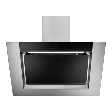
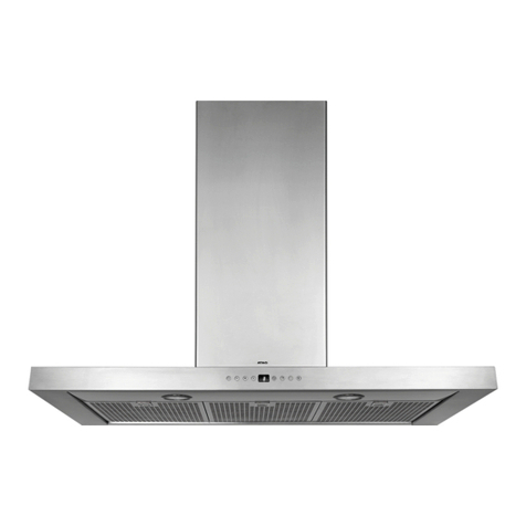
Atag Maxus WG3X Technical manual

gebruiksaanwijzing/installatievoorschrift
instructions for use/installation instructions
mode d’emploi/instructions d’installation
Gebrauchsanweisung/Installationsvorschrift
istruzioni per l’uso/istruzioni per l'installazione
brugsanvisning/installationsforskrifter
οδηγίες χρήσης/οδηγίες εγκατάστασης
WG3/4/8X-EG3/4/8X Maxus
art.nr. 440122000030
postbus 8 - 7070 AA Ulft - Nederland

BENL
IE
FR
CH
CH
AT
LU
LU
GB
BE
DE BE
CHIT
DK
GR
nederlands blz. NL 1 - NL 17
english page GB 1 - GB 17
français page FR 1 - FR 17
Deutsch Seite DE 1 - DE 17
italiano pag. IT 1 - IT 17
dansk side DK 1 - DK 17
ελληνικά σελ.
GR 1 - GR 17

NL 1
voorwoord
De afzuigkap is ontworpen voor huishoudelijk
gebruik en voor de aangegeven doeleinden.
Atag afzuigkappen zijn verkrijgbaar in vele
modellen die smaakvol combineren met ieder
interieur.
Het assortiment biedt verschillende typen
kappen, met ingebouwde of externe motor en
modellen geschikt voor recirculatie.
inleiding
Als u deze handleiding doorleest, bent u snel op
de hoogte van alle mogelijkheden die dit toestel
u biedt. U vindt informatie voor uw veiligheid en
over het onderhoud van het toestel. Verder
vindt u milieutips en aanwijzingen om energie te
besparen.
Bewaar de gebruiksaanwijzing en het
installatievoorschrift. Een eventueel volgende
gebruiker van dit toestel kan daar zijn voordeel
mee doen.
algemeen 1 - 2
inleiding 1
voor uw veiligheid 2
gebruiksaanwijzing 3 - 7
verlichting 3
ventilator 3 – 4
storingen 5
hoe blijft het toestel mooi 6 – 7
installatievoorschrift 8 - 16
installatie 8 – 10
montage 10 – 16
technische gegevens 17
afvoeren verpakking en toestel 17
inhoud

NL 3
verlichting
toestel inschakelen
Schakel het toestel eerst in met de aan/uit toets ( ). Het
lampje boven de toets licht op. U kunt nu gebruik maken van
de overige functiesymbolen
verlichting inschakelen
Leg een vinger op het -symbool. De verlichting schakelt
in op stand 4. Door de vinger op de toets te houden kunt u de
lichtsterkte aanpassen (1-4). Na enkele seconden springt de
instelling naar de volgende stand (volgorde 4-3-2-1-0-1-2-3-4).
Het aantal oplichtende indicatielampjes boven het -
symbool geeft de lichtsterkte aan.
verlichting uitschakelen
Leg een vinger op het -symbool totdat de indicatie boven
het symbool dooft. De verlichting dooft ook als u het toestel
uitschakelt met de aan/uit toets.
toestel inschakelen
Schakel het toestel in met de aan/uit toets ( ). Het lampje
boven de toets licht op. U kunt nu gebruik maken van de
overige functiesymbolen.
ventilator inschakelen
Leg een vinger op het -symbool tot de door u gekozen
stand is bereikt. Als u continu een vinger op het symbool
houdt springt de instelling na enkele seconden een stand
verder (volgorde 0-1-2-3-4-3-2-1-0). De indicatie boven het
symbool geeft de stand aan.
NL 2
voor uw veiligheid
waar u op moet letten
Laat dit toestel door een erkend installateur
aansluiten. Schade ontstaan door verkeerd
aansluiten of verkeerd inbouwen valt niet onder
de garantie.
Maak het toestel spanningsloos voordat met
reparatie of schoonmaken wordt gestart. Bij
voorkeur door de stekker uit het stopcontact te
halen of de werkschakelaar op nul te zetten.
Flamberen onder een afzuigkap is niet
toegestaan. Door de hoge vlammen kan brand
ontstaan. Ook bij uitgeschakelde ventilator.
Houd bij het frituren altijd een oogje in het zeil.
Als het toestel wordt gebruikt in combinatie met
een apparaat dat gas of andere brandstoffen
verbruikt, moet gezorgd worden voor toevoer
van voldoende frisse lucht.
Schakel de afzuigkap in voordat u met koken
begint. Laat na het koken de afzuigkap nog
ca. 10 minuten aan staan. Dit kan ook
automatisch (zie "automatisch nadraaien").
Reinig het toestel regelmatig, zoals aangegeven
in 'hoe blijft het toestel mooi'. Hiermee
voorkomt u dat er een brandgevaarlijke situatie
ontstaat.
Maak eerst het toestel spanningsloos als u de
lampen wilt vervangen! Gebruik uitsluitend
dezelfde lampen met aangegeven wattage.
In verband met eventuele scherpe randen van
de ombouwkoker adviseren wij u tijdens de
montage van de koker werkhandschoenen te
gebruiken.
10 20
ventilator

remedie
Trek de binnenste ring met een
schroevendraaier naar
beneden (zie illustratie).
Let op: het glas ligt hier los in!
Trek het halogeenlampje uit de
fitting en vervang het door een
nieuw 20 W (wandkappen) of
10 W (eilandkappen)
halogeenlampje. Pak het
nieuwe lampje met een schoon
doekje vast.
Verander het afvoerkanaal
(zie installatievoorschrift).
Bel de Servicedienst.
oorzaak
Lamp defect.
Let op:
Gebruik uitsluitend dezelfde
lampen met aangegeven
wattage.
Afvoer te lang of te veel
bochten in het kanaal.
Motor defect.
Motor of bediening defect.
Aansluitsnoer defect.
storing
Verlichting brandt niet.
Afzuigkap maakt lawaai.
Geen afzuiging.
NL 5
storingen
Wanneer het toestel niet goed werkt, betekent dit niet altijd dat het defect is. Probeer het euvel
eerst zelf als volgt te verhelpen. Wanneer onderstaande adviezen niet helpen, bel dan de
servicedienst.
Wanneer het aansluitsnoer beschadigd is moet het vervangen worden door de serviceafdeling van
de fabrikant of gelijkwaardig gekwalificeerde personen om gevaarlijke situaties te voorkomen.
Let op: Maak het toestel spanningsloos voordat met reparatie wordt gestart. Bij voorkeur door de
stekker uit het stopcontact te halen of de werkschakelaar op nul te zetten.
NL 4
ventilator (vervolg)
afzuigcapaciteit regelen
Door het -symbool aan te raken wordt de volgende stand
ingeschakeld. De nieuwe stand wordt aangegeven met
oplichtende indicatielampjes (0-4).
intensiefstand
Leg een vinger op het -symbool totdat 4 indicatielampjes
oplichten. Laat de toets los en de stand wordt ingeschakeld.
ventilator uitschakelen
Leg een vinger op het -symbool totdat alle
indicatielampjes gedoofd zijn. Als u de toets loslaat schakelt
de kap uit.
automatisch nadraaien
Kies eerst de gewenste ventilatorstand. Leg een vinger op
het -symbool. U kunt kiezen of de afzuigkap na 10 of na
20 minuten uit moet schakelen. Het lampje bij de gekozen tijd
licht op.
De afzuigkap schakelt automatisch terug van de ingestelde
stand naar 0. Als de verlichting tijdens het automatisch
nadraaien ingeschakeld was blijft deze ingeschakeld.
vetfilter reinigen
Als het vetfilter-symbool ( ) brandt, het filter direct reinigen.
Plaats het gereinigde filter terug en wis het elektronisch
geheugen door het symbool aan te raken tot het
indicatielampje dooft.
10 20

NL 7
hoe blijft het toestel mooi (vervolg)
vetfilters verwijderen/plaatsen
Verwijder de filters als volgt: schakel de ventilator en de
verlichting uit.
Druk het filter bij de uitsparing naar achteren en kantel de
voorzijde omlaag. Nu kunt u het filter uit de kap nemen.
Het filter kan maar op één manier geplaatst worden. Let op
de juiste positie van het filter (zie illustratie). Houd het filter
zo dat het afgedekte deel van de onderzijde zich midden-
achter bevindt. Aan de buitenzijde is dit herkenbaar aan het
patroon met de kleinere gaatjes.
Plaats nu het filter door eerst de achterkant in de houder te
drukken. Kantel vervolgens de voorzijde naar boven, totdat
dit niet verder gaat en laat dan het filter naar voren
schuiven. Het filter zit nu weer op zijn plaats. Wis het
elektronisch geheugen door ca. 5 seconden op toets te
drukken.
vetfilters reinigen
U kunt de filters in de afwasmachine reinigen. Laat het filter
goed uitlekken -door de sleufjes aan de zijkant- alvorens u
het terugplaatst. De onderzijde maakt u schoon met een
sopje van een afwasmiddel en een vochtige doek.
koolstoffilter vervangen
Vervang het koolstoffilter 2x per jaar. Dit geldt alleen voor
recirculatiekappen.
Plaats het koolstoffilter in de daarvoor bestemde ruimte
boven de filters.
NL 6
hoe blijft het toestel mooi
afzuigkap
Maak de afzuigkap schoon zodra het lampje van de vetfilter-
indicatie brandt.
Het roestvrijstaal aan de buitenzijde van de kap maakt u
schoon met een sopje van afwasmiddel en een vochtige
doek. Het roestvrijstaal krijgt zijn glans terug door af en toe
een roestvrijstaal onderhoudsmiddel of glansmiddel te
gebruiken. Dit glansmiddel brengt een vuilwerend laagje aan
op het roestvrijstaal. Reinig het roestvrijstaal altijd met de
polijstrichting mee.
Atag levert reinigings- en onderhoudsmiddelen voor
afzuigkappen.
Voor informatie over de verkrijgbaarheid, neemt u contact op
met de consumentendienst tel. 0315-687 887.
Gebruik nooit schurende schoonmaakmiddelen (zoals Vim,
groene schuursponsjes of andere pannensponsjes) of
polijstende schoonmaakmiddelen (zoals vloeibare
schuurmiddelen en Jif).
Gebruik nooit agressieve reinigingsmiddelen. Deze kunnen
verkleuringen veroorzaken op roestvrijstaal.

NL 9NL 8
installatie
opmerkingen vooraf
De installatie van een afzuigkap moet geschieden in
overeenstemming met de nationaal en lokaal geldende
voorschriften. De afstand tussen de onderzijde van de
afzuigkap en de kookplaat dient minimaal 65 cm te zijn.
Dit toestel dient door een erkend installateur te worden
aangesloten. Schade ontstaan door verkeerd aansluiten of
verkeerd inbouwen valt niet onder de garantie.
let op:
Wanneer een afzuigkap en een warmtebron (bijv. gas-, olie-
of kolengestookte fornuizen) die lucht uit dezelfde ruimte
verbruiken tegelijk worden ingezet, bestaat de mogelijkheid
dat de afzuigkap de noodzakelijke verbrandingslucht uit de
ruimte afzuigt waardoor een onderdruk in de ruimte kan
ontstaan. De maximaal toegestane onderdruk bedraagt 4 Pa,
opdat er geen verbrandingsgassen van de warmtebron
worden teruggevoerd naar de ruimte zelf. Daarom is een
luchttoevoer noodzakelijk, waarmee de ruimte constant van
verse lucht wordt voorzien.
elektrische aansluiting
Na montage van de afzuigkap dient de stekker bereikbaar te zijn
of dient de afzuigkap d.m.v. een dubbelpolige schakelaar met
contactopeningen van 3 mm spanningsloos te maken te zijn.
Let er bij het aansluiten van de elektrische verbindingen op
dat de contactdoos geaard is en dat het voltage en
frequentie overeenkomt met de op het gegevensplaatje
aangegeven waarden.
Wanneer het aansluitsnoer beschadigd is moet het
vervangen worden door de serviceafdeling van de fabrikant
of gelijkwaardig gekwalificeerde personen om gevaarlijke
situaties te voorkomen.
installatie (vervolg)
afvoer
De afvoer mag in geen geval op een kanaal worden
aangesloten dat ook in gebruik is voor andere doeleinden.
Denk aan de plaatselijk geldende voorschriften met
betrekking tot de beluchting van gasapparaten.
De afvoer kan rechtstreeks door de muur naar buiten
plaatsvinden, mits de muuropening door een rooster wordt
beschermd tegen inregenen en het binnendringen van
bladeren en dergelijke.
De doorlaat van de afvoer mag niet meer dan 20% beperkt
worden door het muurrooster.
Wij adviseren een zo ruim mogelijk afvoerkanaal te plaatsen.
Een kleinere diameter heeft een lagere afzuigcapaciteit en
een hoger geluidsniveau tot gevolg.
Een bocht geeft weerstand. Zorg ervoor dat het kanaal
vloeiend verloopt en zo min mogelijk bochten heeft. Trek de
flexibele pijp zover mogelijk uit.
Controleer voordat u met boren begint of er geen
installatieleidingen aanwezig zijn.

NL 11NL 10
montage (vervolg)
inbouwen wandmodellen
Op de vorige pagina zijn de belangrijkste afmetingen
aangegeven. U kunt de hoogte van de telescooppijp
instellen. Houd wel rekening met de toegestane toleranties.
Monteer de afvoer en de elektrische aansluiting zodanig dat
u ze straks makkelijk op de kap kunt aansluiten.
aftekenen en monteren bevestigingsmateriaal
Zet een verticale hartlijn op de muur (midden van de kap).
Houd de bevestigingsbeugel zo tegen de wand, dat hij tegen
het plafond rust. De markering geeft het midden van de
afzuigkap aan. Markeer de bevestigingsgaten.
Boor de bevestigingsgaten (ø 8 mm).
Monteer de pluggen in de muur en bevestig de
bevestigingsbeugel aan de muur met de bijgeleverde
schroeven (5 x 50 mm).
motormodule aftekenen en monteren
Teken de onderzijde van de kap af op de muur (houd hierbij
rekening met de minimale afstand tot de kookplaat). Geef de
(verticale) hartlijn aan.
Vouw of knip de aftekenmal volgens type en teken de
bovenste bevestigingsgaten af.
Boor de bevestigingsgaten (2x ø 10 mm).
Bevestig de pluggen. Draai 2 moeren in tegengestelde
richting op de draadeinden. Draai de draadeinden tot 20 mm
diep de muur in (zie illustratie).
Verwijder de moeren.
20
installatie (vervolg)
De afvoerstomp heeft een diameter van 150 mm.
Het beste is de afvoerpijp ook met deze diameter uit te
voeren.
Er wordt een verloop van 150 mm naar 125 mm bij het toestel
geleverd voor aansluiting op een 125 mm afvoerpijp.
ATAG levert accessoires voor afvoerkanalen van
afzuigkappen. In de prijslijst vindt u een overzicht van het
assortiment met de bijbehorende typenummers.
¿150/125
410
530
755900
235 240
800-1000
min. 650
130
montage
inbouwmaten wandmodellen
WG3/4/8X

NL 13NL 12
montage (vervolg)
Hang de motormodule aan de draadeinden (1). Draai de
moeren aan. Zorg ervoor dat de module exact waterpas hangt.
Boor de borggaten (2x ø6 mm) en borg de motormodule met
de bijgeleverde kozijnpluggen (6 x 60) (2).
Monteer het afvoerkanaal.
Breng de elektrische aansluiting tot stand.
kap ophangen
Monteer de kap aan de motormodule.
Haak eerst de achterzijde van de kap van onderaf in de
motormodule (1).
Kantel vervolgens de voorzijde omhoog (2), zodat de twee
bijgeleverde bouten (M5 x12) ingedraaid kunnen worden (3).
Stel met deze bouten de kap waterpas.
Maak de stekkerverbindingen in de kap.
1
1
2
23
telescooppijp ophangen
Let op: Bij recirculatie (WG8) mogen de ventilatiesleuven niet
afgedekt worden door de onderste telescooppijp.
Schuif de omgezette rand van de bovenste telescooppijp van
onderaf tussen de bevestigingsbeugel en de muur en schuif
de telescooppijp tegen het plafond. De telescooppijp zet
zichzelf vast.
Haak de onderste telescooppijp om de bovenste
telescooppijp en laat deze zakken.
Bevestig de filters en test de werking van de afzuigkap.
montage (vervolg)

NL 15NL 14
montage (vervolg)
bovenste telescooppijp ophangen
Monteer de pluggen en draadeinden aan het plafond. Draai
2 moeren in tegengestelde richting op de draadeinden. Draai
de draadeinden tot 20 mm in de pluggen in het plafond.
Verwijder de moeren.
Plaats de bovenste telescooppijp over de draadeinden.
Plaats de ringen en draai de moeren vast.
montagekoker
Schuif de montagekoker zover in de bovenste pijp totdat de
onderrand zich op de juiste afstand tot het aanrecht bevindt
(zie illustratie).
Maat A = 340 mm
Zet de montagekoker vast met de vier bouten (M5 x 12),
ringen en moeren M5.
20
A
650
montage (vervolg)
inbouwen eilandmodellen
Hierboven zijn de belangrijkste afmetingen aangegeven. U
kunt de hoogte van de telescooppijp instellen. Houd wel
rekening met de toegestane toleranties.
Het verdient aanbeveling om de afzuigkap met behulp van
een montagelift op te hangen. Indien geen lift aanwezig, is
het raadzaam om de montage met meerdere personen uit te
voeren.
Monteer de afvoer en de elektrische aansluiting zodanig dat
u ze straks makkelijk op de kap kunt aansluiten.
aftekenen
Teken de montagegaten af op het plafond met behulp van de
aftekenmal.
Boor de bevestigingsgaten (4 x 10 mm).
¿150/125
520
700
755
1000
250 240
800-1025
min. 650
130
EG3/4/8X
inbouwmaten eilandmodellen

NL 17NL 16
technische gegevens
typenummer : zie gegevensplaatje in de kap
energiesoort: 230 V - 50 Hz
aansluitwaarde: zie gegevensplaatje
afmetingen (h x b x d): zie “inbouwmaten”
keurmerk: Kema
Dit toestel voldoet aan de geldende CE richtlijnen.
externe motoren
Let op: Wanneer een toestel met externe motor
gebruikt wordt, dan adviseert ATAG de volgende
typen externe motoren te gebruiken:
WA111B5U WA300B5U
WA111C5U WA300C5U
ASVM0021 AS000387
ASVM0025 ASVM0023
De verpakking van het toestel is recyclebaar.
Gebruikt kunnen zijn:
–karton
–poly-ethyleenfolie (PE)
–CFK-vrij polystyreen (PS-hard-schuim)
–polypropyleen banden om de doos
Deze materialen op verantwoorde wijze en conform
de overheidsbepalingen afvoeren.
De overheid kan u ook informatie verschaffen over
het op verantwoorde wijze afvoeren van
afgedankte huishoudelijke apparaten.
afvoeren verpakking en toestel
montage (vervolg)
motormodule
Draai twee schroeven (4,2 x 9,5) voor de helft in de
achterste gaten (1) in de motormodule (zie illustratie).
Schuif de motormodule van onderaf omhoog in de
montagekoker en haal de motormodule iets naar achteren
zodat deze in de montagekoker haakt en blijft hangen (2).
Monteer de voorste twee schroeven (4,2 x 9,5) zoals
aangegeven in de illustratie (3). Draai ook de achterste twee
schroeven (1) vast.
Maak de benodige stekkerverbindingen.
Monteer het afvoerkanaal.
onderste telescooppijp
Schuif de onderste telescooppijp over de motormodule naar
boven (1).
Houd de pijp omhoog door een pen of schroevendraaier
voorzichtig in het hiervoor bedoelde gat in de voorzijde van
het motorhuis te drukken (2).
kap monteren
Monteer de kap aan de motormodule. Haak eerst de
achterzijde van de kap van onderaf in de motormodule (1).
Kantel vervolgens de voorzijde omhoog (2), zodat de twee
bijgeleverde bouten (M5 x 12) ingedraaid kunnen worden (3).
Stel met deze bouten de kap waterpas.
Maak de stekkerverbindingen in de kap.
Laat de onderste telescooppijp zakken zodat deze in de rand
van de kap schuift (4).
Bevestig de filters en test de werking van de afzuigkap.
1
2
123
4
1
3
2

GB 1
introduction
When you have read this manual, you will
quickly be aware of all the facilities the
appliance can offer you. You can read about
safety and how you should look after the
appliance. In addition you will find
environmental tips and instructions that can
help to save energy.
Keep the manual. Any later user of this
appliance could benefit from them.
general 1 - 2
introduction 1
for your safety 2
instructions for use 3 - 7
lighting 3
fan 3 –4
faults 5
how to keep the appliance looking good 6 –7
installation instructions 8 - 17
installation 8 –10
assembly 10 –16
technical data 17
disposal of packaging and appliances 17
table of contentsforeword
The extractor hood has been designed for
domestic use and for the purposes stated. Atag
extractor hoods are available in many different
models, which fit elegantly into all interiors.
The Atag range offers various types of hoods,
some with built-in motors and others suitable
for recirculation.

lighting
switching on the appliance
First switch the appliance on using the on/off button . The
light above the button lights up. You can now make use of the
other function symbols.
switching on the lighting
Touch the -symbol. The lighting switches on at setting 4.
You can adjust the light intensity (1-4) by keeping your finger
on the button. After a few seconds, the lighting jumps to the
next setting (in the sequence 4-3-2-1-0-1-2-3-4). The number
of indicator lights on above the -symbol indicates the light
intensity.
switching off the lighting
Touch the -symbol and keep your finger on it until the
indicator light above the symbol goes out.The lighting also
goes out if you switch the appliance off using the on/off
switch.
switching on the appliance
Switch the appliance on using the on/off button ( ). The
light above the button lights up. You can now make use of the
other function symbols.
switching on the fan
Touch the -symbol and keep your finger on it until the
setting you want has been reached. If you continue to keep
your finger on the symbol, after a few seconds the setting will
jump to the next setting (in the sequence 0-1-2-3-4-3-2-1-0).
The indicator lamp above the symbol indicates the setting.
10 20
fan
GB 2
for your safety
Please note
This appliance should be connected by a
registered fitter. Damage arising from incorrect
connection or incorrect fitting is not covered by
the guarantee.
Disconnect the appliance before starting with
cleaning or reparation. It is recommended that
you do this by removing the plug from the
socket or by setting the isolation switch to zero.
Never flambe under an extractor. The high
flames can cause fire. Even if the ventilator is
switched off.
When deep-frying, always keep a close watch.
If the appliance is used together with
equipment which uses gas or other fuels, then a
sufficient supply of fresh air must be ensured.
Switch the extractor hood on before starting to
cook. After cooking, allow the extractor hood to
continue to run for approx. 10 minutes. This can
also be done automatically (see 'automatic
continued running').
Clean the appliance regularly, as shown in
'maintenance'. This minimises the chance of a
fire starting.
Switch off the electricity before replacing the
light bulbs! Only use the same sort of light bulbs
with the same Wattage.
In view of possible sharp edges on the chimney
we advise you to wear working gloves when
fitting the chimney.

solution
Pull the inner ring downwards
using a screwdriver (see
illustration).
NB: the glass is loose!
Pull the halogen lamp out of
the fitting and replace it with a
new 20 W halogen lamp (wall
hoods) or 10 W halogen lamp
(island hoods). Use a clean
cloth to hold the new lamp.
Change the discharge duct
(see installation instructions).
Phone the Service department.
cause
Lamp defective.
NB:
Only use the same type of lamp
with the wattage stated.
Discharge duct too long or has
too many bends.
Motor defective.
Motor or controls defective.
Connection lead defective.
fault
Lighting does not work.
Extractor hood makes a lot of
noise.
No extraction.
GB 5
faults
Please check the following points which may solve the problem, before calling the service
department.
If the connection cable is damaged, it should be replaced by the service department of the
manufacturer or similarly qualified persons in order to prevent dangerous situations from arising.
NB: Disconnect the appliance from the mains before starting any repairs, preferably by removing
the plug from the socket or by setting the isolation switch to zero.
GB 4
fan (continued)
adjusting extractor capacity
Touching the - symbol switches the fan to its next
setting. The new setting is indicated by the indicator lights
(0-4) lighting up.
intensive setting
Keep your finger on the - symbol until the 4 indicator
lights come on. Let go of the button and the setting is
switched on.
switching the fan off
Touch the - symbol and keep your finger on it until all the
indicator lights go out. When you let go of the button, the
hood switches off.
automatic continued running
First select the fan setting desired. Touch the - symbol.
You can choose whether the extractor hood is turned off
after 10 or after 20 minutes. The light next to the time
selected lights up.
The extractor hood automatically switches back from the
setting chosen to 0. If the lighting was switched on during
the automatic continued running, it will remain switched on.
cleaning the grease filter
If the grease filter symbol ( ) lights up, you should clean
the filter immediately.
Put the filter back in place after cleaning and erase the
electronic memory by touching the symbol and keeping
your finger on it until the indicator light goes out.
10 20

GB 7
maintenance (continued)
removing/replacing grease filters
Remove the filters as follows: switch the fan and the lighting
off.
Push the filter at the edge of the niche to the back and pull
the front end down. You can now remove the filter from the
hood.
The filter can only be put back into place in one way. Take
note of the correct position of the filter (see illustration).
Hold the filter in such a way that the covered part of the
underside is at the centre rear. This is recognizable on the
outside by the pattern with the smaller holes.
Put the filter back into place by first pushing the rear side
into the holder. Then push the front upwards until it cannot
go any further and let the filter slide forwards. The filter is
now once again in place. Erase the electronic memory by
pressing the button for approx. 5 seconds.
cleaning the grease filters
You can clean the grease filters in the dishwasher. Allow the
filter to drain well - through the slits in the side - before
putting it back.
replacing the carbon filter
Replace the carbon filter twice a year. This only applies to
recirculation hoods.
Put the carbon filter in the place intended for it above the
filters.
GB 6
maintenance
extractor hood
Clean the extractor hood as soon as the grease filter
indicator light comes on.
The stainless steel on the outside of the hood can be
cleaned with soapy water and a damp cloth. The stainless
steel will regain its shine if you occasionally use a stainless
steel care product or polish. The polish imparts a dirt-
resistant layer to the stainless steel. Always clean the
stainless steel in the direction of polishing.
Never use abrasive cleaning agents (such as Vim, green
scouring pads or other scourers) or polishing cleaning
products (such as liquid scourers and Jif).
Never use caustic cleaning agents. These can cause
stainless steel to discolour.

GB 9
installation (continued)
discharge
The discharge should not be connected to a duct which is
also used for other purposes under any circumstances.
Bear in mind any local regulations concerning the ventilation
of gas appliances.
The discharge may pass straight through the wall to the
outside, provided that the wall opening is protected - by
means of a grating - against rain, leaves, and the like getting
in.
The passage of the discharge may not be restricted by the
wall grating by more than 20%.
We advise the use of as large a discharge duct as possible.
A duct with a smaller diameter will have a low extraction
capacity and produce higher noise levels.
Bends produce resistance. Make sure that the duct has a
smooth run and has as few bends as possible. Draw the
flexible pipe out as far as possible.
Before starting to drill, check that there are no installed
pipes present.
GB 8
installation
some preliminary remarks
An extractor hood should be installed in accordance with
national and local regulations. The minimum distance
between the underside of the extractor hood and the hob
should be 65 cm.
The appliance should be connected by a registered fitter.
Damage arising from incorrect connection or incorrect
fitting is not covered by the guarantee.
NB:
If an extractor hood and a heat source (for example, gas-,
oil- or coal-fired cookers) which take air from the same
room are in use at the same time, there is a possibility that
the extractor hood will cause an underpressure in that room.
The maximum permitted underpressure is 4 Pa, so that no
combustion gases from the heat source can find their way
back into the room. For this reason, an air supply is required
- to provide a constant supply of fresh air to the room.
electrical connection
The extractor hood's plug should be accessible after fitting
or the extractor hood should be isolated by a bipolar switch
with 3 mm plug pins.
When making the electrical connections, make sure that the
socket is earthed and that the voltage and frequency
correspond to the values given on the data plate.
If the connection cable is damaged, it should be replaced by
the service department of the manufacturer or similarly
qualified persons in order to prevent dangerous situations
from arising.

GB 11
assembly (continued)
installation wall hood
The most important dimensions are shown on the previous
page. You can set the height of the telescopic pipe. Take the
allowable tolerances into account.
Position the discharge and the electrical connection in such
a way that it will be easy to hook up the hood.
marking out and fitting fixing materials
Draw a vertical centre line on the wall (centre of the
extractor hood).
Place the fastening clip against the wall so that it rests
against the ceiling. The arrow on the flanged rim indicates
the middle of the cooker hood. Mark the attachment holes to
be drilled.
Drill the holes (ø8 mm).
Put the plugs into the wall and fix the fixing bracket to the
wall with the screws supplied (5 x 50 mm).
marking out and fitting motor module
Mark the position of the underside of the hood on the wall
(bear in mind the minimum distance to the hob). Mark the
(vertical) centre line.
Fold or cut the template depending on type and mark the
upper fixing holes.
Drill the fixing holes (2 x ø10 mm).
Fix the plugs. Screw two nuts onto the threaded ends in the
opposite direction. Screw the threaded ends into the wall
leaving 20 mm projecting (see illustration).
Remove the nuts.
20
GB 10
installation (continued)
The discharge stump has a diameter of 150 mm. It is best if
the discharge pipe also has this diameter.
A reducing piece (150 mm to 125 mm) is supplied with the
appliance for connection to a 125 mm discharge pipe.
ATAG supplies accessories for discharge ducts for extractor
hoods. You will find an overview of the range with the
appropriate type numbers in the price list.
¿150/125
410
530
755900
235 240
800-1000
min. 650
130
assembly
building-in dimensions wall hood
WG3/4/8X

GB 13
fitting the telescopic pipe
NB: During recirculation (WG8), the ventilation slits must not
be covered by the lower telescopic pipe.
Slide the flanged end of the upper telescopic pipe upwards
between the fixing bracket and the wall, and slide the
telescopic pipe against the ceiling. The telescopic pipe locks
into position.
Hook the lower telescopic pipe onto the upper telescopic
pipe and allow it to drop.
Put the filters in place and test the extractor hood.
assembly (continued)
GB 12
assembly (continued) Suspend the motor module on the threaded ends (1). Screw
the nuts on. Make sure that the motor module is exactly level.
Drill holes (2 x ø6 mm) and secure the motor module with the
fixing pins supplied (6 x 60) (2).
Fit the discharge duct.
Connect the motor module electrically.
fitting the hood
Fit the hood to the motor module.
First hook the rear of the hood into the motor module at the
bottom (1).
Then lift the front up (2) so that the two bolts supplied (M5 x
12) can be screwed in (3). Use these bolts to level the hood.
Make the plug connections in the hood.
1
1
2
23

GB 15
assembly (continued)
fitting the upper telescopic pipe
Fix the plugs and threaded ends in the ceiling. Screw two
nuts onto the threaded ends in the opposite direction. Screw
the threaded ends into the plugs in the ceiling, leaving
20 mm projecting.
Remove the nuts.
Place the upper telescopic pipe over the threaded ends. Put
the washers on and tighten the nuts.
mounting socket
Slide the mounting socket into the upper pipe until the
bottom edge is at the correct distance from the worktop (see
illustration).
Dimension A = 340 mm
Fasten the mounting socket using the four bolts (M5 x 12),
washers and nuts M5.
20
A
650
GB 14
assembly (continued)
fitting island models
The most important dimensions are given above. You can
adjust the height of the telescopic pipe. Bear in mind the
permitted tolerances.
It is advisable to suspend the hood with the help of an
assembly lift. If there is no lift present, it is advisable to carry
out the mounting with more than one person.
Position the discharge and the electrical connection in such
a way that it will be easy to hook up the hood.
marking
Mark the holes to be drilled on the ceiling by means of the
stencil.
Drill the holes (4 x 10 mm).
¿150/125
520
700
755
1000
250 240
800-1025
min. 650
130
EG3/4/8X
building-in dimensions island hood

GB 17
technical data
type number: see data plate in the hood
power supply: 230 V - 50 Hz
connected load: see data plate
dimensions (h x w x d): see "fitting dimensions"
approvals mark: Kema
This appliance complies with the CE directives.
external motors
NB: For appliances with an external motor, ATAG
recommends the use of the following types of external
motors:
WA111B5U WA300B5U
WA111C5U WA300C5U
ASVM0021 AS000387
ASVM0025 ASVM0023
The packaging of the appliance is recyclable. It can be
made up of:
–cardboard
–polyethylene
–CFC free polystyrene (PS rigid foam)
–polypropylene straps around the box
Please dispose of these materials in a responsible way in
accordance with the regulations of your local authority.
Your local authority will also be able to give you information
about disposing disused household appliances in a
responsible way.
disposal of packaging and appliances
GB 16
assembly (continued)
motor module
Screw two screws (4.2 x 9.5) halfway into the rear holes (1)
in the motor module (see illustration).
Slide the motor module upwards in the mounting socket and
pull the motor module backward slightly so that it catches in
the mounting socket and remains suspended (2).
Fix the front two screws (4.2 x 9.5) as shown in the
illustration (3). Then tighten the rear two screws (2).
Make the necessary plug connections.
Fit the discharge duct.
lower telescopic pipe
Slide the lower telescopic pipe upwards over the motor
module (1).
Hold the pipe up by carefully pushing a pen or screwdriver
into the hole that has been made for this purpose in the front
of the motor housing (2).
fitting the hood
Fit the hood to the motor module. First hook the rear of the
hood into the motor module from underneath (1). Then push
the front upwards (2), so that the two bolts supplied (M5 x
12) can be screwed in (3). Level the hood using these bolts.
Make the plug connections in the hood.
Allow the lower telescopic pipe to drop (4) so that it slides
into the edge of the hood.
Put the filters in place and test the extractor hood.
1
2
123
4
1
3
2
This manual suits for next models
8
Table of contents
Languages:
Other Atag Ventilation Hood manuals

Atag
Atag WS1011LM Operation manual

Atag
Atag WU7011GM Operation manual

Atag
Atag WS9011ECR User manual

Atag
Atag WS6211RC User manual

Atag
Atag WS90292FM User manual

Atag
Atag WV60 MS Series User manual

Atag
Atag WS6211IM User manual

Atag
Atag WS90 A Series Technical manual

Atag
Atag ES9011EM Operation manual

Atag
Atag WS9111MR/A01 User manual

Atag
Atag WV60 BM Series User manual

Atag
Atag WS90211JM/A03 User manual

Atag
Atag WU7011RM User manual

Atag
Atag WS9011JM User manual

Atag
Atag ES9011EM User manual

Atag
Atag WS90211BAM User manual

Atag
Atag WV6211NM User manual

Atag
Atag WI60211BC User manual

Atag
Atag WV6211AC User manual

Atag
Atag WV6311LM User manual