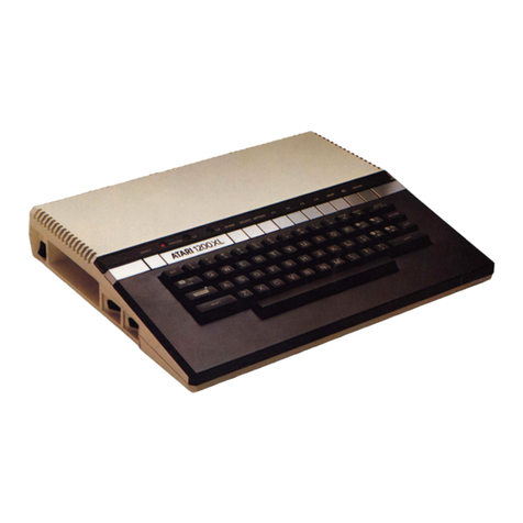
Atari 1200 XL Quick start guide

Printed in U.S. America Atari, Incorporated FD100217
February 1983 ev. by jer/eightbitter
2014

Atari believes that the information described in this manual is accurate and reliable,
and much care has been taken in its preparation. However, no responsibility, financial
or otherwise, shall be accepted for any consequences arising out of the use of this
material. Information contained herein I subject to change. Revisions may be issued
to advise of such changes and or additions.
Correspondence regarding this document should be forwarded to Manager of Technical
Support, Consumer Product Service, Atari, Incorporated, 845 W. Maude Avenue, Sunnyvale,
CA 94086

TABLE OF CONTENTS
Section Title Page
INTRODUCTION V
1 THEORY OF OPERATION ~ 1-1
User Interface 1-2
Mechanical Description 1-3
Digital Hardware 1-5
6502 (Modified) CPU Microprocessor 1-5
Alphanumeric Television Interface Controller 1-6
(Antic Display Processor)
Graphics Television Interface Adaptor (GTIA) 1-7
POT Keyboard Integrated Circuit (POKEY) 1-8
Peripheral Interface Adaptor (PIA) 1-9
Memory (ROM and RAM) 1-11
Memory Management Unit (MMU) 1-11
RF Modulator 1-11
Power Supply 1-11
System Interface 1-11
Serial Input Output (SIO Interface) 1-12
Keyboard Interface 1-13
Controller Jack Interface 1-14
Cartridge Interface 1-15
Monitor Interface 1-16
LED Board Interface I-16
2 SCHEMATICS AND SILKSCREENS 2-1
Drawings 2-2 to 2-12
3 TESTING 3-1
Overview 3-1
Equipment Needed 3-1
Self Test 3-1
MEMORY TEST Screen 3-2
AUDIO VISUAL TEST Screen 3-2
KEYBOARD TEST Screen 3-3
ALL TESTS 3-3
Using the SALT 2.05 Diagnostic Cartridge 3-3
COLOR BAR TEST 3-6
ANY VIDEO TEST 3-7
GRAY BAR TEST 3-g
DISPLAY OPTIONS 3-9
RAM TEST 3-9
1200XL Home Computer III

Field Service Manual
TABLE OF CONTENTS (Cont)
Section Title Page
4 SYMPTOM CHECKLIST 4-1
Adjustments & Replacements 4-3
Console Disassembly 4-3
Console Assembly 4-3
Keyboard Removal Replacement 4-4
RF Modulator Adjustment 4-4
Sound Adjustment 4-4
Color Adjustment 4-4
5 1200XL PARTS LIST 5-1
6 SERVICE BULLETINS 6-1
TABLE OF ILLUSTRATIONS
Figure Title Page
1-1 1200XL Left Side Panel 1-1
1-2 1200XL Back View 1-2
1-3 1200XL Functional Block Diagram 1-4
1-4 6502 (Modified) CPU Pin Assignments 1-6
1-5 ANTIC Display Processor Pin Assignments 1-7
1-6 GTIA Pin Assignments 1-8
1-7 POKEY Pin Assignments 1-9
1-8 PIA Pin Assignments 1-10
1-9 SIO Interface Pin Assignments 1-13
1-10 Keyboard Interface Pin Assignments 1-13
1-11 Controller Jack Interface Pin Assignments 1-14
1-12 Monitor Interface Pin Assignments 1-14
1-13 Cartridge Interface Pin Assignments 1-15
3-1 SALT Header 3-4
3-2 SALT Menu 3-4
3-3 COLOR BAR Test Screen 3-5
3-4 ANY VIDEO Test Screen 3-6
3-5 GRAY BAR Test Screen 3-7
3-6 Display Option Screen 3-7
3-7 RAM TEST Screen 3-9
4-1 1200XL Console and RF Shield 4-2
1200XL Home Computer
Field Service Manual IV

INTRODUCTION
The Atari 1200XL Computer Field Service Manual is a reference guide for the service
technician.
This Field Service Manual is organized in six sections:
•THEORY OF OPERATION - Overview of how the 1200XL works and what its basic
assemblies look like.
•SCHEMATICS AND SILKSCREENS - Electrical drawings and layouts of the 1200XL
printed circuit board.
•TESTING - Review of Diagnostic Tests available for diagnosing 1200XL problems.
•SYMPTOM CHECKLIST - Failure information to assist the experienced technician
arrive at a rapid diagnosis of 1200XL pcoblems.
•PARTS LIST - Detailed breakdown of all parts used in the 1200XL.
•SERVICE BULLETINS - Section to be used to hold Field Change Orders, Upgrade
Bulletins and Tech Tips.
1200XL Home Computer V
Field Service Manual

SECTION 1
THEORY OF OPERATION
The Atari 1200XLTM is an enhanced version of the existing Atari computer systems. It can be
used with any existing Atari peripheral devices which are compatible with the 400TM 800TM
computer, although not all are necessary.
The console contains 64K of RAM and has an operating system which contains two 8K X 8
ROMs. The console also contains the keyboard with a HELP key, four application function
keys, a single cartridge slot, connector jacks for adding peripherals and hand controllers, a
detachable (RF) TV interface cable and three status LED's.
Use Figures 1-1 and 1-2 as reference for the following discussion.
Figure 1-1. 1200XL Left Side Panel
1200XL Home Computer
Field Service Manual 1-1

Figure 1-2. 1200XL Back View.
User Interface
The Atari 1200XL is a general purpose microcomputer which uses a 6502 (modified)
microprocessor. The 1200XL console is the central processing unit for its respective system.
The left side panel (refer to Figure 1-1) contains the power ON OFF switch, one cartridge slot
and two controller jacks. The controller jacks accept the X-Y joystick and the paddle controllers
available from Atari.
The rear panel (refer to Figure 2-1) contains the Serial Input Output (I O) jack, the RF cable
jack, the monitor jack, the channel 2-3 switch, and the Power Jack.
The console has a full stroke 54 key alphanumeric keyboard, which includes special characters
and controls, a space bar, three LED indicators, and 11 function keys.
The 11 function keys above the keyboard are made of brushed and formed aluminium
nameplate material. A translucent plexiglass strip above the function keys indicates the
operation (function) and covers the three LEDs.
1200XL Home Computer
Field Service Manual 1-2

From left to right the function keys and LED indicators are:
RESET - Interrupts and restarts the operating system or cartridge.
POWER - Lights when Power to the unit is ON.
L1 - Lights if the keyboard is disabled.
L2 - Lights if the International character set is selected. START - Starts the game or program.
SELECT - Selects different games.
OPTION - Allows the player to choose among the variations of a program.
F1-F4 - User programmable function keys. The following functions are only applicable when
software, such as BASIC; is inserted.
Press F 1 to move cursor up.
Press F2 to move cursor down.
Press F3 to move cursor left.
Press F4 to move cursor right.
HELP - Press to display self-test options.
- Inverse Video
BREAK - Used for interrupt of program.
Mechanical Description
The 1200XL computer console contains a single motherboard which houses all the chips of the
system and provides connectors for interfacing external modules to the console. It includes the
CPU, RAM, ROM Operating System and power supply, and includes all functions except for
the keyboard and LED display. The motherboard uses a common address bus, data bus and
clock lines. The sixteen-line address bus allows the microprocessor to directly address 64K of
memory locations. The eight-line data bus provides the communication and data path between
the functional modules. The various power requirements are routed from the power supply
throughout the console.
The keyboard is connected to the PC Board by a 15-conductor ribbon cable terminating in a
molex connector. The LED board is connected to the PC Board by a 5-conductor ribbon cable.
Figure 1-3 is a block diagram of the functional flow of the 1200XL.
1200XL Home Computer
Field Service Manual 1-3
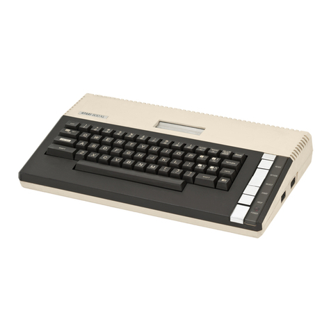
Figure 1-3. 1200XL Functional Block Diagram.
1200XL Home Computer
Field Service Manual 1-4

Digital Hardware
The digital hardware consists of:
•The 6502 (modified) CPU microprocessor
•The Alphanumeric Television Interface Controller (the ANTIC Display Processor)
•The Graphics Television Interface Adaptor (GTIA)
•The POT Keyboard Integrated Circuit (POKEY)
•The Peripheral Interface Adaptor (PIA)
•The Memory (ROM and RAM)
•Miscellaneous Iogic
•Memory Management Unit (MMU)
•Delay Line
6502 (modified) CPU Microprocessor
The 6502 (modified) CPU microprocessor contalns register flags, interconnections, arithmetic
logic, control logic, and all recognized operation codes. The characteristics of the
microprocessor are:
•Byte-oriented structure
•151 opcodes
•Decimal and binary arithmetic modes Seven addressing modes
•True indexing Stack pointer
•Two interrupt levels 64K address range
•Integral clock circuit
•Single +5 volt DC power Requirement
Figure 1-4 is an illustration of the 6502 (modified) CPU Pin Assignments.
1200XL Home Computer
Field Service Manual 1-5

Figure 1-4. 6502 (Modified) CPU Pin Assignments
Alphanumeric Television Interface Controller (The ANTIC Display Processor
The ANTIC Display Processor is a custom display microprocessor with an instruction set
customized for graphics generation. It also has the ability to control bus and RAM REFRESH.
Figure 1-5 is an illustration of the ANTIC Display Processor pin assignmens.
1200XL Home Computer
Field Service Manual 1-6

Figure 1-5. Antic Display Processor Pin Assignments
Graphics Television Interface Adaptor (GTIA)
The GTIA interfaces with the ANTIC processor on one side and with the video summation
circuitry on the other. Its primary task is to generate color and luminance signals from the
display information bit stream it receives from the ANTIC Display Processor.
Figure 1-6 is an illustration of the GTIA pin assignmens.
1200XL Home Computer
Field Service Manual 1-7

Figure 1-6. GTIA pin assignments
POT Keyboard Integrated Circuit (POKEY)
The POKEY is a Custom Large Scale Integrated Circuit (LSI) chip. It is used for audio
generation, Serial Input Output (SIO) control, controller interface scan and keyboard scan.
Figure 1-7 is an illustration of the POKEY pin assignmens.
1200XL Home Computer
Field Service Manual 1-8

Figure 1-6. POKEY pin assignments
Peripheral Interface Adaptor (PIA)
The PIA is a general purpose Input Output (I O) chip.
Figure 1-7 is an illustration of the PIA pin assignmens.
1200XL Home Computer
Field Service Manual 1-9

Figure 1-8. PIA pin assignments
1200XL Home Computer
Field Service Manual 1-10

Memory (ROM and RAM)
The 1200XL operating system is resident to two 8K X 8 ROMs. The ROMs input CPU address
lines AO through A12 and the chip selects from the address decoding circuitry and generates
data on CPU data lines DO through D7. RAM is organized as 8-64K x 1 chips, one for each data
line. 48K RAM is directly available.
Memory Management Unit (MMU)
The Memory Management (Address Decoding) circuitry consists of a Hard Array Logic
(HAL), one 3 to 8 decoder and a few gates. The input to this circuitry are the address lines A8
thru A15 and control signals like ROM enable (From PIA) and Refresh. The outputs of this
circuitry are GTIA chip select, POKEY chip select, PIA chip select, O.S. ROM selects, RAM
selects, cartridge selects and COMM A, COMM B, COMM C.
The RF Modulator
The RF Modulator inputs the composite video from the video summation circuitry and the
monoaural audio signals and produces a modulated signal suitable for the television.
The modulated signal will have the following characteristics with a 75Ω termination:
Maximum Voltage: 2 mV
Minimum Voltage: 1 mV
Audio Sound Carrier Frequency: 4.5 MHz
Frequency Response:
Ch. 3 61.25 MHz ± 0.5
Ch. 2 55.25 MHz
Power Supply
The 1200XL has a linear power supply. The power supply electronics is resident on the
motherboard. The power supply accepts a 9VAC input through the power jack. An external
step-down transformer accepts 115 VAC from the power line and steps it down to 9VAC. The
9VAC input is rectified by a bridge rectifier and then regulated power outputs from the
regulators are bussed on separate power rails to power distinct sections of the motherboard. All
power rails have a common ground.
The DC. output of each regulator is 5V ±5% (1.7A Max). Input voltage is 9 VAC. Input power
is 31 VA.
SYSTEM INTERFACE
The 1200XL provides the following interfaces:
•The Serial Input Output (SIO) interface
•The keyboard interface
•The controller jack interface
•The cartridge interface
•The monitor interface
•The LED board interface
1200XL Home Computer
Field Service Manual 1-11

Serial Input Output (SIO) Interface
The Atari 1200XL communicates with peripheral devices over an asynchronous serial port
(19.2K Baud RAte Max). Data is transmitted and received as 8 bits of serial data (LSB sent
first) preceded by a logic zero start bit and succeeded by a logic one stop bit. The serial data out
is transmitted as positive logic. The serial DATA OUT line always assumes its new state when
the serial CLOCK OUT line goes high; CLOCK OUT goes low in the center of the DATA
OUT time.
The bus protocol specifies that all commands must originate from the computer, and that
peripherals present data on the bus only when commanded to do so. Every bus operation goes
to completion before another bus operation is initiated (no overlap). An error detected at any
point in the bus operation will abort the entire sequence. A bus operation consists of the
following elements:
Command Frame (From Computer)
Acknowledge Frame (From Peripheral)
Optional Data Frame (To or From Computer)
Complete Frame (From Peripheral)
Command Frame
The serial bus protocol provides for three types of commands:
1) Data Send
2) Data Receive
3) Immediate (No Data-Command Only)
1200XL Home Computer
Field Service Manual 1-12

Figure 1-9 is an illustration of the SIO pin assignments.
PIN PIN
1 Clock In 7 Command
2 Clock Out 8 Motor Control
3 Data Into CPU 9 Proceed
4 GND 10 Ready (Computer ON)
5 Data Out 11 Audio In (175 MV)
6 GND 12 +12 VDC (Not used on 1200XL)
13 Interrupt
Figure 1-9. SIO Interface Pin Assignments (looking into jack on unit)
Keyboard Interface
Figure 1-10 is an illustration of the keyboard interface pin assignments.
The 1200XL keyboard uses a 15-pin Molex Connector, which provides inputs to POKEY,
GTIA (SO,S1,S2) and CPU (Reset).
Figure 1-10. Keyboard Interface Pin Assignments.
1200XL Home Computer
Field Service Manual 1-13

Controller Jack Interface
The 1200XL provides two controller jack interfaces. Both are functionally and electrically
identical. The controller jacks are 9-pin D-type connectors.
Figure 1-11 is an illustration of the controller jack pin assignments.
1. (Joystick) Forward Input 6. Trigger Input
2. (Joystick) Back Input 7. +5 volts
3. (Joystick) Left Input 8. Ground
4. (Joystick) Right Input 9. Pot A Input
5. Pot B Input
Figure 1-11. Controller Jack Pin Assignments (from left side of 1200XL)
Monitor Interface
The Monitor Interface is a 5-pin DIN connector.
Figure 1-12 is an illustration of the monitor interface pin assignments
Figure 1-12. The Monitor Interface pin assgnments
1200XL Home Computer
Field Service Manual 1-14

Cartridge Interface
The cartridge interface is a 30 pin edge connector.
Figure 1-13 is an illustration of the cartridge interface pin assignments.
Figure 1-13. Cartridge Interface Pin Assignments (from left side of 1200XL)
1200XL Home Computer
Field Service Manual 1-15
Other manuals for 1200 XL
4
Table of contents
Other Atari Desktop manuals