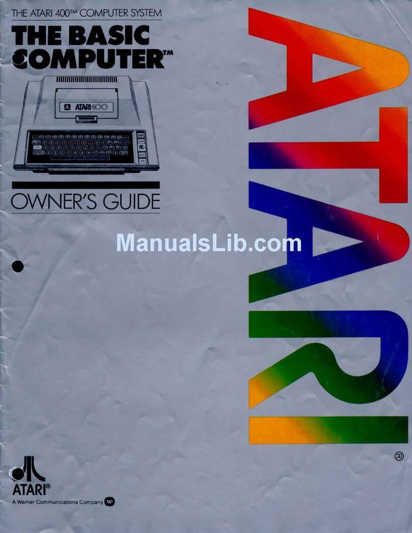
Atari 400 Quick start guide

ATARI HOME COMPUTER
FIELD SERVICE MANUAL
40/S

ATARI believes that the information described in this manual is accurate and reliable,
and much care has been taken in its preparation. However, no responsibility, financial
or otherwise, shall be accepted for any consequences arising out of the use of this
material. Information contained herein is subject to change. Revisions may be issued
to advise of such changes and/or additions.
Correspondence regarding this document should be forwarded to Manager of Technical
Support, Consumer Product Service, ATARI, Incorporated, 1312 Grossman Road,
Sunnyvale, CA 94086, U.S. America.

TABLE OF CONTENTS
Section Title Page
INTRODUCTION ix
1THEORY OF OPERATION l-I
Overview l-l
User Interface 1-2
*00/S00 Mechanical Description 1-3
Motherboard 1-4
Central Processing Unit 1-5
ROM Personality PCB 1-5
RAM PCB 1-5
Keyboard 1-6
Power Supply 1-6
Program Cartridge 1-6
*00/800 Electronic Discussion 1-7
Central Processing Unit 1-7
CPU 6502 Integrated Circuit 1-7
Alphanumerical Television 1-S
Interface Controller
Color Television Interface 1-10
Adaptor
Grcphic Television Interface 1-10
Adaptor
I/O Decoder 1-10
Composite Video 1-10
Motherboard Console -*00 l-l 1
Pot Keyboard Integrated 1-11
Peripheral Interface Adaptor I-1
1
Key-In Key-Out Integrated 1-12
Circuit
Memory Map Decoder 1-12
I/O Decoder 1-13
Motherboard Console -800 1-U
Bi-directional Data Buffer l-U
ROM Personality Board 1-15
Power Supply 1-16
ROM Cartridge 1-17
Accessories 1-17
AC Power Adaptor 1-17
TV Switch Box 1-17
'BASIC Program Cartridge 1-17
2SILKSCREEN AND SCHEMATICS 2-1
3TROUBLESHOOTING AND TESTING 3-1
Overview 3-1
Tests ^3-1
Equipment Needed 3-1
Testing With and Without 3-2
the SALT II Cartridge
ATARI Home Computer iii

TABLE OF CONTENTS (Cont)
Section Title Page
Overview of Tests 3-2
Power-Up Test 3-2
Keyboard Test 3-2
RAM and ROM Test 3-2
SALT nMenu 3-5
Color Bar Test 3-6
Any Video Test 3-7
Gray Bar Test 3-S
Keyboard Test ,. . .»3-9
Switch Test 3-9
Tone Test 3-9
Display Options 3-10
Port Test 3-10
Verify ROM Test =3-11
RAM Test 3-12
MTest ...-•. 3-15
Star Raider Test 3-16
Shake Test 3-16
Bumin 3-16
Description of the Other Functions 3-17
Production Test 3-17
Boot B3-17
Examine 3-17
Adjust 3-17
Summary 3«1
7
if DISASSEMBLY/ASSEMBLY MAINTENANCE i^-i
ATARI *00 Home Computer Console -Disassembly .»..,.. ^1
Keyboard and Power Supply Access «if-1
Keyboard Removal if-3
Power Supply Removal ti~4
CPU, RAM and Motherboard Access ^6
CPU and RAM Removal if-6
ATARI 800 Home Computer Console -Disassembly ^-S
Access to RAM Boards and if-S
ROM Board
Access to Power Supply and ^9
Keyboard Assembly
Remove Top Cover if-9
Remove the PCB Module ^-10
Remove the Power Supply „..i^-i 1
Access to CPU Printed Circuit Board if-1
2
Access to Motherboard ^-13
Keyboard Removal i^-l /f
ATARI Home Computer iv

TABLE OF CONTENTS (Cont)
Section Title Page
ATARI WO Home Computer Console -Assembly ^15
Module Assembly Reassembly it~l5
Keyboard Installation *-I6
Power Supply Installation ^^-16
Top Cover Installation i^-17
ATARI 800 Home Computer Console -Asc^mbly H~i7
Keyboard Assembly ^17
Motherboard Installation ,i^-^7
CPU PCB Installation i^-lS
Power Supply Installation *-l 8
Module Assembly Installation Into Top Cover *-19
Bottom Cover Installation t^iS
RAM and ROM Installation *-20
Cartridge Door Assembly f^-20
PCB Contact Cleaning and Lubricating ^20
Tools Required i^-20
Procedure ^21
Visual Inspection f^-21
5WO DIAGNOSTIC FLOWCHARTS 5-1
6WQ/800 SYMPTOM CHECKLIST 6-1
7800 DIAGOSTIC FLOWCHARTS 7-1
8GAME CONTROLLERS 8-1
Joystick (X-Y Controller) S-i
Joystick (X-Y ControUer) Check 8-3
Equipment Needed 8-3
Procedure 8-3
Game Paddle 8-4
Game Paddle Controller Check 8-5
Equipment Needed 8-5
Procedure 8-5
9PARTS LIST g.l
*00 Computer 9-2
800 Computer 9_7
10 SERVICE BULLETINS lO-l
ATARI Home Computer

LIST OF ILLUSTRATION
Figure Title "Page
1-1 ATARI *00 Home Computer Console 1-1
1-2 ATARI 800 Home Computer Console 1-2
1-3 MPU Pin Assignments 1-8
i-4 ANTIC Pin Assignments 1-9
1-5 CTIA/GTIA Pin Assignments 1-10
1-6 POKEY Pin Assignments l-ll
1-7 PIA Pin Assignments 1-12
1-8 WO Motherboard Flow Diagram 1-18
1-9 *00 Power Supply 1-19
I-IO 800 Motherboard Flow Diagram 1-20
1-1
1
800 Power Supply Flow Diagram 1-21
1-12 800 Personality Board 1-22
1-13 CPU Board Flow Diagram 1-23
I-U 8K Dynamic RAM Flow Diagram 1-2^
1-15 16K Dynamic RAM Flow Diagram 1-25
1-1
6
Game Cartridge Flow Diagram 1-26
1-17 ATARI Home Computer System 1-27
Block Diagram
2-1 WO Motherboard Siikscreen 2-3
2-2 *00 Motherboard Schematic 2-4
2-3 400 Power Supply Siikscreen 2-6
2-^ *00 Power Supply Schematic 2-7
2-5 800 Motherboard Siikscreen 2-9
2-6 300 Motherboard Schematic 2-10
2-7 800 Power Supply Siikscreen 2-12
2-8 800 Power Supply Schematic 2-13
2-9 800 Personality Board Siikscreen 2-U
2-10 800 Personality Board Schematic 2-15
2-1
1
CPU Board Siikscreen 2-16
2-12 CPU Board Schematic 2-17
2-13 8K RAM Board Siikscreen 2-18
2-U 8K RAM Board Schematic 2-19
2-15 16K RAM Board Siikscreen 2-20
2-16 16K RAM Board Schematic 2-21
3-1 Special Graphics Test 3-3
3-2 SALT Header 3-/*
3-3 SALT II Menu 3-5
3-A Color Bar Test Screen 3-6
3-5 Any Video Test Screen 3-7
3-6 Gray Bar Test Screen 3-8
3-7 Port Test Screen 3-10
3-8 RAM TEST Screen 3-13
ATARI Home Computer vi
LIST OF ILLUSTRATION (Cont)
Figure Title Page
*-l ATARI *00 Console, Bottom Cover Screw Location *-2
^-2 ATARI *00 Console, Top Cover Removal *-3
*-3 ATARI *00 Console, Keyiaoard Removal *-4
*-* ATARI *00 Console, Power Supply Removal ^5
*-5 ATARI *00 Console, Module Assembly *-7
*-6 ATARI 800 Console, Cartridge Door -*-9
Assembly Removal
^'7 ATARI 800 Console, Bottom Cover Removal i^-10
if-S ATARI 800 Console, Module Assembly Removal *-l 1
*-9 ATARI 800 Console, Power Supply Removal (^-12
if-lO ATARI 300 Console, CPU Printed Circuit -*-13
Board Removal
'f-l 1ATARI 800 Console, Motherboard Removal ^--15
*-12 ATARI 800 Console, Keyboard Removal ifr-l5
5-1 Keyboard Connection Chart 5-38
5-2 Defective RAM Boards 5-39
7-1 Keyboard Connection Chart 7-38
7-2 Defective RAM Boards 7-39
8-1 Joystick (X-Y ControUer) 8-2
8-2 Joystick Schematic 8-3
8-3 Game Paddle 8-4
8-4 Game Paddle Schematic 8-5
LIST OF TABLES
Table Title Page
1-I Memory Map Selected Lines 1-13
1-2 I/O Decoder Select Line 1-14
3-1 Port Test Legend 3-12
3-2 Defective RAM Boards 3-U
3-3 Defective RAM Identified 3-15
5-1 Clock Circuit 5-36
5-2 Defective RAM Boards 5-39
5-3 Port Test Legend 5-40
7-1 Clock Circuit 7-36
7-2 Defective RAM Boards 7-39
7-3 Port Test Legend 7-40
ATARI Home Computer vii

INTRODUCTION
The ATARI ^00/800 Home Computer"^^ Field Service Manual is organized in 10
Sections:
iTHEORY OF OPERATION -overview of how the *00 and 800 Home
Computers work-
2SILK5CREEN5 AND SCHEMATICS -electrical layouts and drawings for
major components.
3TESTING AND TROUBLESHOOTING -overview of tests which assist in
diagnosing malfunctions.
*DISASSEMBLY/ASSEMBLY -detaUed instructions to completely
disassemble and assemble both units.
5WO DIAGNOSTIC FLOWCHARTS -detailed procedures for
troubleshooting and repairing the *00 Computer.
6*00/800 SYMPTOM CHECKLIST -quick reference for troubleshooting
each computer.
7800 DIAGNOSTIC FLOWCHART -detailed procedures for
troubleshooting and repairing the 800 Computer.
8GAME CONTROLLERS -overview of hand controller construction and
recommended test procedures.
9PARTS LIST -detailed breakdown of all parts used in each unit.
10 SERVICE BULLETINS -section to be used to hold Field Change Orders,
Upgrade Bulletins, and Tech Tips.
This manual is designed for use by both the experienced and inexperienced service
technician. The Diagnostic Flowcharts (Sections 5and 7) provide detailed
diagnostics and repair procedures for technicians not completely familiar with the
ATARI *00/800 Home Computers. The Symptom Checklist (Section 6) provides a
rapid repair reference for the more experienced technician.
ATARI Home Computer ix

SECTION I
THEORY OF OPERATION
OVERVIEV
The Atari *00 Computer Home Console contains the central processor unit (CPU) and
memory in the form of the Operating System (read-only-memory (ROM)) and 8K or
16K of user programmable random access memory (RAM). The console contains the
keyboard, cartridge slot, controller jacks, and serial input/output (I/O) port for
connecting peripheral devices (see Figure l-U.
rawci
oNforr
SWITCH
KiirmsAL
CONNECTOa
JACK
SYSTIM RESET
SWITCH
Figure 1-1. ATARI ^00 Home Computer Console
ATARI Home Computers 1-1

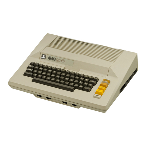
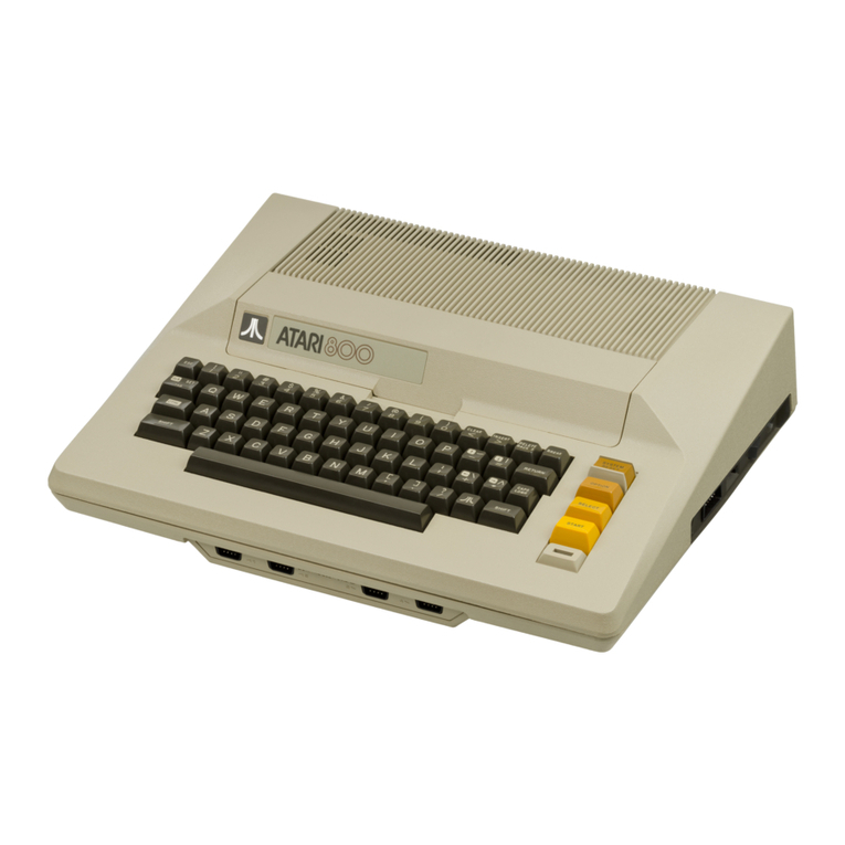
The ATARI 800 Home Computer Console contains the CPU and memory in the form of
the Operating System (iOK of read-only-memory (ROM)) and SK to i6K (standard) of
user programmable random access memory (RAM); plus two expansion sockets for
additional RAM modules (maximum ^8K). The console also contains the keyboard,
cartridge slots (2), controller jacks and aserial I/O port for connecting peripheral
devices (see Figure 1-2).
HAND
CONTtOUn
tACKS
SYSTEM HSCT
SWITCM
Figure 1-2. ATARI 800 Home Computer Console
USER INTERFACE
The ATARI *00/8G0 Home Computer Consoles are general purpose microcomputers
using the 6502 microprocessor. The ATARI i^OO/800 Consoles are the central
processing units for their respective systems. Each console comes standard with a
built-in typewriter style keyboard, 8K/16K of RAM, ROM operating systems,
connector jacks for adding peripherals and hand controllers, and a15-foot Radio
Frequency (RF) cable for connection to the user's television set.
The controller jacks on the front of both consoles accepts the X-Y (joystick) and
paddle hand controllers available from ATARI.
ATARI Home Computers 1-2

The right side panel of the Atari *00 Computer Console contains aperipheral jack,
power ON/OFF switch, and apower jack. The channel 2/3 switch is located on the
back of the console. This switch changes the console transmission frequency to either
channel 2or channel 3(refer to Figure 1-1).
The right side panel of the Atari 800 Home Console contains amonitor jack, a
peripheral jack, achannel 2/3 switch, apower ON/OFF switch, and apower jack (refer
to Figure 1-2),
Both Console keyboards provide afull alphanumeric character set, cursor controls, and
special purpose keys- The alpha keys when used in conjunction with the Control
(CTRL) key become special graphic symbols. To the right of the keyboard is the power
ON light and four special control keys (refer to Figure 1-1 and Figure 1-2).
From the top to the bottom they are:
SYSTEM RESET -Interrupts whatever the computer is doing and restarts the
Operating System or Program Cartridge.
OPTION -Interrupt used by the Program Cartridge to choose among
the variations within agame or program.
SELECT -Interrupt used to select one of several games or programs
on the Program Cartridge.
START -Interrupt used to Start the game or program selected from
the Program Cartridge.
»00/800 MECHANICAL DESCRIPTION
The Atari WO/SOO Computer Home Consoles are made up of seven major functional
modu es they are:
Motherboard
Central Processing Unit (CPU) Printed Circuit Board
ROM Personality Printed Circuit Board (Operation System) (300 Only)
RAM Printed Circuit Board(s)
Keyboard
Power Supply Board
Program Cartridge
ATARI Home Computers 1-3

The Printed Circuit Boards (PCBs) piug into sockets on the motherboard, using a
common Address Bus, Data Bus and clock lines. The various power requirements are
routed from the power supply through the motherboard to all printed circuit boards.
The keyboard connects directly to the motherboard through aribbon connector. The
sixteen-Une Address Bus allows the microprocessor to directly address 64K of memory.
The eight-line Data Bus provides the communication and data path between the
functional modules.
Figures 1-8 thru 1-17 at the end of this section provide function block diagrams of
PCBs in the *00/800 systems.
Motherboard
The motherboard ties all components of the computer system together. It also
performs avariety of logic functions. All PCBs and connector cables plug into the
motherboard and allow communication between the functional blocks of the '^OO and
SOO Computer Consoles. The motherboard also performs the following:
•Generates a3.58 MHz master clock for the Central Processing Unit's PCB.
•Generates the Power-ON RESET for the Central Processing Unit PCB and
the peripherals.
•Provides the driving circuitry for the Key-Press signal from the Central
Processing Unit PCB to the Console speaker.
•Converts signals from the various hand controllers into recognizable data
for the microprocessor.
•Buffers and drives the data lines between the Central Processing Unit PCB,
the RAM PCBs, and the remainder of the system.
•Does the first memory map decoding of the possible 64K address locations
into 8K blocks for the microprocessor.
•Generates control signals for the peripheral devices.
•Receives video data from the Central Processing Unit PCB, converts it
into acomposite video and routes it to the power supply PCB.
•Combines the sound from the Computer system and the audio track of
prerecorded cassettes.
•Develops the sound subcarrier for the television audio as part of the
composite video.
ATARI Home Computers 1-^

Central Processing Unit
The Centrai Processing Unit (CPU) PCB is the controller of the entire Console system.
The CPU PCB contains the 6502 microprocessor, and the ANTIC and CTIA (or GTIA)
chips. The CPU PCB controls the Console system and its peripheral devices through
address lines (to select which device it needs to communicate with) and data lines (to
transmit and/or receive data from aselected device) common to the entire system.
Operating instructions for the microprocessor come from the ROM Operating System
on the Personality PCB, Additional functions of the CPU PCB are:
•deceives the master clock from the motherboard and generates Phase 1(/I
or Ph 1) and Phase 2(/2 or Ph 2) clocks used to synchronize the entire
system.
•Transmits aREFRESH signal at least every 2miliseconds to refresh the
dynamic RAM chips on the RAM PCB(s).
•Receives the four TRIGGER lines from the fire button on each of the hand
controller accessories.
•Receives the lines from the four control switches located to the right of
the keyboard-
•Generates video signals to be processed by the motherboard before they
are sent to the RF module on the Power Supply PCB.
ROM Personality PCB
The ROM Personality PCB contains information in Read-Only Memory (ROM), the
program of operating instructions for the microprocessor. Two *K ROMs contain the
Operating System, and one 2K ROM contains the arithmatic functions used for BASIC
programming. Information is retrieved from the ROMs by addressing aparticular
location on the ROM using the Address Bus. The data contained at that location is
placed on the Data Bus to be read by the microprocessor.
The ROM Personality PCB also provides the CHIP SELECT signals used to select LSI
chips throughout the Console system and for the bi-directional data buffers on the
motherboard.
RAM PCB
The Random Access Memory (RAM) PCB performs the function of temporary data
storage for the system. The RAM is dynamic, requiring REFRESH, and is available in
SK or 16K versions.
Each RAM chip on the RAM PCB has only seven address lines. To address 16K
locations requires Uaddress lines. To accomplish this, aI*-bit address is
ATARI Home Computers 1-5

sent to the address demultiplexer, which first passes the lower seven bits to the RAM
chips as aRow Address. After an appropriate delay, the highest seven bits are passed
as aColumn Address. Data is then either put into or taken out of the location
selected. The direction of data flow is determined by the Read/Write line.
REFRESH occurs at least every two milliseconds. The REFRESH signal is generated
on the CPU Board.
Keyboard
The typewriter-style keyboard is used to generate alphanumeric characters as well as
special graphic symbols. The keyboard allows the operator to communicate with the
console system for writing programs or responding to preprogrammed cassettes or
cartridges. The keyboard consists of 57 normally open switches. The switches are
scanned at arapid rate and when aswitch is found closed, that scan pattern is sent to
the Pot Keyboard Integrated Circuit (POKEY) for encoding.
Power Supply
The Power Supply PCB receives 9VAC from an external power adaptor (transformer)
and provides +5Vdc, +12Vdc, and -5Vdc for the Console system. The Power ON/OFF
switch is mounted on the Power Supply PCB and removes input power by opening the
9Vac lines. An interlock switch breaks power to the system when the operator opens
the top panel of the Console to install or remove Program Cartridges.
The RF Module resides on the Power Supply PCB, The RF Module generates the RF
output for the video screen from the composite video signals received from the
motherboard, and is switchabie to television channel 2or 3,
Voltages:
+5Vdc A-Supply voltage for the logic PCBs.
t-5Vdc B-Specially filtered for the video circuitry,
+12Vdc and -5Vdc -Supply voltage for the dynamic RAM chips.
Program Cartridge
The Program Cartridge permanently stores the microprocessor instructions for a
particular application. It consists of two i^K ROM chips mounted on the enclosed PCB,
Information is received from the ROM chips by addressing the memory locations
assigned to the Program Cartridge slot(s). Data in the memory locations is then
placed on the Data Bus lines.
ATARI Home Computers 1-6

400/800 ELECTRONIC DISCUSSION
The remainder of this section provides adetailed discussion of the functions of the
seven major modules.
Central Processing Unit
The Central Processing Unit (CPU) PCB contains the 6502 CPU (or MPU) chip (A303),
t^c CTIA or GTIA chip (A301), the ANTIC chip (A3a2), tri-level address buffers (Z303
and Z304), and the clock generator (Z302A and Z302B).
CPU 6502 Integrated Circuit
The 6502 microprocessor contains register flags, interconnections, arithmetic logic,
and control logic, all recognized operation codes. The characteristics of the 6502
microprocessor ares
Byte-oriented structure
151 opcodes
Decima' and binary arithmetic modes
Seven addressing modes
True indexing
Stack pointer
Two interrupt levels
64K address range
Integral clock circuit
Single +5 volt dc power requirement
Figure 1-3 is an illustration of the 6502 pin assignments. The functions of the pins are
explained on the following pages.
ATARI Home Computers 1-7

vss Ci
RDY C2
^I c>
IS^ c*
N.C C'
NMI q*
YP*C c7
vcc e: S
A« e: 9
Al c10
Aa ca
A3 n12
A« c13
A3 cIt
At c15
A7 i: IC
AS n17
A9 cIS
AlO Ll»
All L20
MCSfiMZ
to JRES
39 3h
3S 3SO
37 J^(IN)
36 3N.C
33 3N.C
3* 3R/V
33 3at
32 3Dl
31 302
30 303
«JD*
21 305
27 3D6
26 307
23 3AI2
2* 1AI3
23 1Alt
22 11A13
21 [1VSS
Figure 1-3. MPU Pin Assignments
Alphgtnumenc Television Interface Controller
The primary function of the Alphanumeric Television Interface Controller (ANTIC)
chip is to fetch data from memory, independent of the processor, for display on the
video screen.
Figure 1-4 is an illustration of ANTIC Pin Assignments.
ATARI Home Computers 1-8

GROUND VSS
CTIA Data ANJJ
CTIA Data AN I
Light Pen EP
CTIA Data AN2
Interrupt Input RNMl
Interrupt Output NMl
Refresh REF
HALT HATt
Address Bus A3
Address Bus A2
Address Bus Al
Address Bus AH
Read/Write R/W
Ready RDY
Address Bus AlO
Address Bus A12
Address Bus A13
Address Bus AH
Address Bus A15
*0 D* Data Bus
39 D5 Data Bus
38 D6 Data Bus
37 07 Data Bus
36 ft^ Reset
35 FPhJf Fast Phase C
3* Phtf Phase Clock
33 D3 Data Bus
32 D2 Data Bus
31 Dl Data Bus
30 D^ Data Bus
29 Ph2 Phase 2Clock
23 A4 Address Bus
27 A5 Address Bus
26 A6 Address Bus
25 A7 Address Bus
2* AS Address Bus
23 A9 Address Bus
22 All Address Bus
21 VDD 5V Power
Figure 1-^. ANTIC Pin Assignments
ATARI Home Computer I-9

Color Television Interface Adaptor
The Color Television Interface Adaptor (CTIA) chip retrieves graphics data from
memory vU the ANTTC DMA process- This data is routed to the CTIA eraohics
registers. Figure 1-5 illustrates the pin assignments for the CTIA and GTIA,
Address Bus
Address Bus
Ground
Data Bus
Data Bus
Data Bus
Data Bus
Trigger
Trigger 1
Trigger 2
Trigger 3
Console Sw
Console Sw 1
Console SW 2
Console SW 3
PAL Color Delay
Color Delay
Alphanum. Data
Alphanum. Data 1
Alphanum. Data 2
Al 1
A^ 2
V5S 3
D3 4
D2 5
Dl 6
00 7
T^ S
Tl 9
T2 10
T3 11
5^ 12
SI 13
S2 1*
S3 13
PAL 16
DEL 17
ANO IS
ANl 19
AN2 20
*0 A2
39 A3
38 A*
37 D*
36 D5
35 D6
3* D7
33 R/W
321 C5I
31 CS2
30 PH2
29 FPHO
23 OSC
27 VDD
26 hAlT
25 -CSYNC
21- LUM2
23 LUM 1
22 LUM 2
21 COL
Address Bus
Address Bus
Address Bus
Data Bus
Data Bus
Data Bus
Data Bus
Read/Write
Chip Select 1
Chip Select 2
Phase 2Input
Clock Out
Oscillator Input
Power
HALT
Output Sync
Luminance 2Output
Luminance 1Output
Luminance Output
"Color
Figure 1-5. CTTA/GTIA Pin Assignments
Graphics Television Interface Adaptor
The Graphic Television Interface Adaptor (GTIA) is an extended capabilities version of
the CTIA, having additional high-resolution modes-
I/O Decoder
The I/O Decoder integrated circuit (ZiOl) is aone-eight decoder demultiplexer. The
Iv^?^®^®^ "** ^"^*^ '^ *® *^° ^<^ 200' but is labeled ZlOl in the 800 Console and
Z1Q5 in the WO Console.
Composite Video
J^^.'tP^T ,^? ^.°° Motherboards route the Composite video signals (COMP CHROMA,
COMP LUM, MOD, and COMP VIDEO) to the Power Supply to build the RF videtJ
output.
ATARI Home Computers 1-10

Motherboard Console -^QO
The *00 Console Motherboard contains the Pot Keyboard (POKEY) (AiOl) chip ,the
Peripheral Interface Adaptor chip (PIA) (A102), the ROM Personality chips {A1Q3 thru
A105), the Keyboard Key-In/Key-Out analog multiplexers, the Memory Map Decoder
(Z103), the controller jacks (JlOl thru JIO*), the CPU connector jack (JllO), the
Keyboard connector jack, RAM connectors and Cartridge connectors-
Pot Keyboard Integrated Circuit
The Pot Keyboard Integrated Circuit (POKEY) provides the Interface between the
Keyboard, the Serial I/O ports, and the microprocessor. It also contains four semi-
independent audio channels, each with its own frequency, noise, and volume control.
Figure i-6 shows the pin assignments of the POKEY.
Ground
Data Bus
Data Bus
Data Bus
Data Bus
Data Bus
Phase 2Clock
Put Scan
Pot Scan
Pot Scan
Pot Scan
Pot Scan
Pot Scan
Pot Scan
Pot Scan
Keyboard Scan
5VPower
Keyboard Scan
Keyboard Scan
Keyboard Scan
VSS
D3
D*
D3
06
D7
02
P6
P7
P*
P5
P2
P3
PO
PI
K^
VDD
kJ
K3
*0 D2
39 Di
3S DO
37 AUDIO
36 AO
35 Al
34 A2
33 A3
32 R/W
31 CSl
30 CSQ
29 IRQ
28 SOD
27 OCLK
26 BCLK
25 KRl
2* SID
23 KO
22 m
21 K2
Data Bus
Data Bus
Data Bus
Audio Out
Address Bus
Address Bus
Address Bus
Ac^iiress Bus
Read/Write Control
Chip Select
Chip Select
Interrupt Request
Serial Output Data
Serial Output Clock
Bidirectional Clock
Keyboard Scan
Serial Input Data
Keyboard Scan
Keyboard Scan
Keyboard Scan
Figure 1-6. POKEY Pin Assignments
Peripheral Interface Adaptor
The Peripheral Interface Adaptor (PIA) (6520) has two 8-bit programmable I/O ports
and two control bits for each port, for atotal of ten lines per port. Figure 1-7 shows
the pin assignments of the PIA.
ATARI Home Computers l-ll

^l—
PAT fc 2
PAl c3
PA2 c*
P« c5
PA* c«
PW c7
PA« qS
p^r
9
10
PBI cn
PB2 c12
PBS c13
PB« c1«
PM c1^
PW c1«
PB7 17
IS
L
-c 1»
vcc mc: 20
MCSU20
40
39
3S
37
3«
33
3*
33
32
31
30
2f
2S
27
2S
23
2*
23
22
21
n**—^cAi
^»• CA2
—J ,„„ ^iR^
3^iRQB
3-^ RSI
n-* M»
>
3
J.
1
3
n
3
3
3^
3-»-
3^
3^
3^
DO
Dt
D2
D3
D*
D3
Dt
07
ENABLE
CSl
CS2
R/ir
Figure 1-7. PIA Pin Assignments
Key-In Key-Out Integrated Circuits
These two *051 (ZlOl and Z102) integrated circuits are used to scan the Keyboard for
input data on the '^00 and 800 Computer Consoles. The *051 integrated circuits are
analog multiplexers controlled by the input lines A, B, Cand X.
Memory Map Decoder
The Memory Map Decoder integrated circuit (Z103) on the 400/800 Motherboard is a
one-of-ten decoder. Four input lines (pins 12, 13, and U, and 15) determine which
output line is selected. The 400/800 Computer Console uses only three of the input
lines (pins 13, 14, and 15 and pin 12 being grounded) for atotal of eight selected output
lines (SO -S7), Refer to Table l-I for the line selected for each input combination.
ATARI Home Computers 1-12
Other manuals for 400
14
This manual suits for next models
1
Table of contents
Other Atari Desktop manuals

Atari
Atari PC3 User manual

Atari
Atari 520STE Quick start guide

Atari
Atari 400 User manual

Atari
Atari 800 XL ROSE Quick start guide

Atari
Atari 800 User manual

Atari
Atari 400 Use and care manual

Atari
Atari ST Use and care manual

Atari
Atari 800 User manual

Atari
Atari 1200 XL Quick start guide

Atari
Atari 400 User manual

Atari
Atari 1200 XL Quick start guide

Atari
Atari STACY User manual

Atari
Atari 400 The Basic Computer User manual

Atari
Atari 600XL Product information sheet

Atari
Atari Faicon030 User manual

Atari
Atari 130XE User manual

Atari
Atari 850 User manual

Atari
Atari 1200 XL User manual

Atari
Atari 800 XL ROSE User manual

Atari
Atari MEGA STe User manual