ATC iLifestyle User manual

INSTRUCTIONS FOR INSTALLATION AND USE
A73023520 - 2022-01
Wi smart uid electric thermal radiator

THIS PAGE INTENTIONALLY LEFT BLANK

3
A73023520
IMPORTANT:
- In order to avoid overheating, do not cover the radiator.
The radiator itself is marked with the standard
“Do not cover” symbol.
- Do Not sit on the radiator.
- This appliance is not intended for outdoor use.
- If the power cord is damaged, it must be changed by the
manufacturer, their after-sales service or persons qualied
to do so, to avoid possible danger.
- The radiator must not be located underneath an electrical
connection. The electric supply line should be protected with
a high sensitivity dierential device (RCBO).
- The radiator must be installed so that around it there is
sucient space for proper circulation of hot air, always
respecting the minimum distances indicated in the LOCATION
section. Anyone who is in the bathtub or shower must not
have access to the switches and other power operation
devices, respecting 0.6 m distance between the radiator and
the bath or shower.
- Mounting is an important part of safety. To perform the correct
installation, go to MOUNTING section.
- This heating apparatus holds a specic amount of special oil.
Repairs where it is necessary to open the oil tank must only
be made by the manufacturer, which should be contacted in
case of any oil leakage.
- This appliance can be used by children aged 8 years and
above and persons with reduced physical, sensory or mental
abilities or lack of experience and knowledge, if they have

4A73023520
been given supervision or appropriate training regarding the
use of the device in a safe way and they understand the
dangers involved. Children must not play with the appliance.
Cleaning and maintenance must not be performed by
unsupervised children.
- Children under 3 years should be kept out of reach of the
appliance unless they are constantly supervised.
- Children between age 3 and younger than 8 years old should
only turn on / o the device whenever it has been placed or
installed at its normal operating position provided they are
supervised or have received instructions concerning use of
the appliance safely and understand the risks that the device
has. Children from 3 years and under 8 years old should not
plug in, regulate, clean the appliance or perform maintenance.
CAUTION - Some parts of this product can become hot
and cause burns. Pay particular attention when children
and vulnerable people are present.
- If the radiator is discarded, ensure it is recycled responsibly
and follow any local provisions concerning recycling of oil.
- Do not use this heater in the immediate surroundings of a
bath, a shower or a swimming pool.
- Do not use this heater if it has been dropped or if there are
visible signs of damage to it.
- Do not install Radiator covers of any kind over the heater
- Do not use this heater in small rooms when they are occupied
by persons not capable of leaving the room on their own,
unless constant supervision is provided.

5
A73023520
- To reduce the risk of re, keep textiles, curtains or any other
ammable material a minimum distance of 1 m from the air
outlet.
CONTENTS
1x ATC iLifestyle Smart Radiator
2x Metal Brackets
2x Plastic Covers (top)
2x Locking Plastic Covers
4x Grey Wall Plugs
4x Hex-Head Fixings
1x Instruction Manual
1x Quick Start Guide
1x Quick Start guide for WiFi connection
1x Quick Start Guide for Voice Assistants
Please contact Sales@ATC.ie if any of the above are missing
DESIGNED AND MADE IN SPAIN

6A73023520
INDEX
1. INTRODUCTION........................................................................................................................ 7
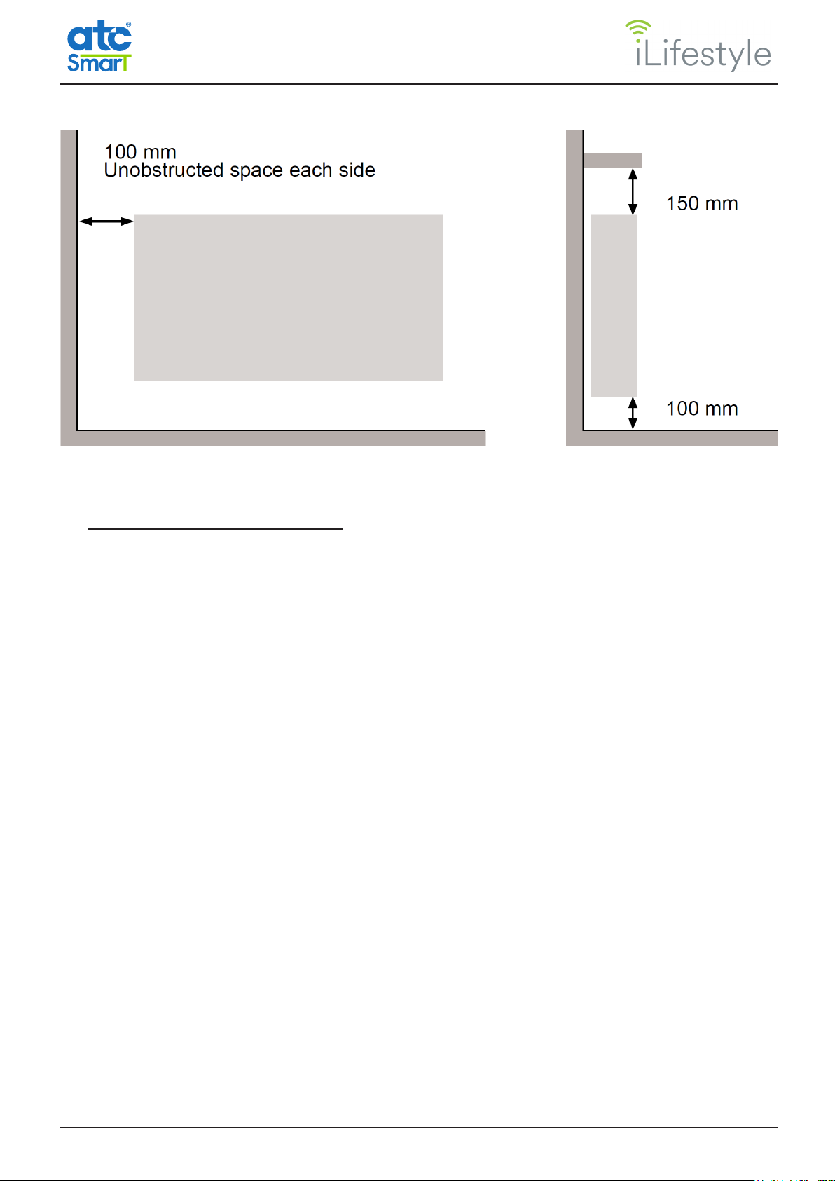
2. LOCATION ................................................................................................................................. 7
3. ELECTRICAL CONNECTION................................................................................................... 8
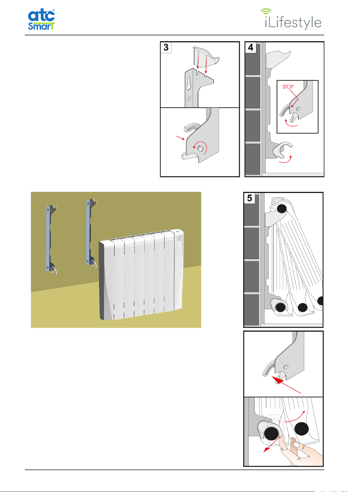
4. MOUNTING ................................................................................................................................ 9
5. OPERATION............................................................................................................................. 11
5.1 CONTROL PANEL............................................................................................................ 11
5.2 TURNING THE RADIATOR ON AND OFF....................................................................... 11
5.3 LINKING THE RADIATOR TO THE WiFi NETWORK..................................................... 12
5.3.2.1 Linking a radiator to a WiFi network................................................................ 14
5.3.4.1 WiFi Radiator Name........................................................................................ 15
5.3.4.2 WiFi Radiator Code......................................................................................... 15
5.3.4.3 Link WiFi ......................................................................................................... 16
5.3.4.4 WiFi Network................................................................................................... 17
5.3.4.5 WiFi Info.......................................................................................................... 19
5.3.4.6 Firmware Update ............................................................................................ 19
5.4 SELECTING THE OPERATING MODE ........................................................................... 20
5.4.5.1 Energy Meter Type.......................................................................................... 23
5.4.5.2 Rate ................................................................................................................ 24
5.4.5.3 Reset............................................................................................................... 25
5.4.6.1 Brightness level at rest.................................................................................... 26
5.4.6.2 Maximum brightness Time ............................................................................. 27
5.4.6.3 Setting the time ............................................................................................... 27
5.4.6.4 Power Limitation ........................................................................................... 27
5.4.6.5 Open Windows ............................................................................................... 28
5.4.6.6 Adaptive start control ..................................................................................... 28
5.4.6.7 Language ........................................................................................................ 28
5.4.6.8 Currency ........................................................................................................ 28
5.4.6.9 Reset factory defaults ..................................................................................... 28
5.5 HEATING AND TEMPERATURE DISPLAY...................................................................... 29
5.6 MANUAL MODE ............................................................................................................... 29
5.7 OPEN WINDOWS FUNCTION......................................................................................... 30
5.8 ADAPTIVE START CONTROL FUNCTION ..................................................................... 31
5.9 KEYBOARD LOCK........................................................................................................... 31
5.10 INTERNAL PARAMETERS CONFIGURATION................................................................ 31
5.11 EASY MODE .................................................................................................................... 33
6. CHARACTERISTICS TABLE ................................................................................................. 35
7. MAINTENANCE ....................................................................................................................... 35
8. ECODESIGN TABLE............................................................................................................... 36
9. NOTES ...................................................................................................................................... 36
10. CE DECLARATION OF CONFORMITY................................................................................. 37
11. UKCA DECLARATION OF CONFORMITY ........................................................................... 38
12. WARRANTY ............................................................................................................................. 39
13. CORRECT DISPOSAL OF THIS PRODUCT ........................................................................ 40

7
A73023520
WiFi SMART FLUID ELECTRIC THERMAL RADIATOR
1. INTRODUCTION
Before switching the radiator on, carefully read these instructions which will help to ensure correct
operation of the device. Keep the instructions for future reference
2. LOCATION
It is recommended to locate the radiator as close as possible to the coldest wall in the room.
however it is not recommended to install the radiator on external walls without any insulation. If it is
necessary to mount on an uninsulated external wall the section of wall behind the thermal radiator
must be insulated.
In bathrooms, the radiators must not be installed inside restricted areas. In the UK the radiator
must be mounted outside Zone 2, In Ireland the radiator must be mounted outside Zone 3.
The control unit switches must not be reachable, directly or indirectly, by a person in the bath/
shower or using the wash basin.
Classication of the bathroom zones
Under no circumstances may the thermal radiator be
located under an electrical outlet.

8A73023520
Choose the location of the thermal radiator following the minimum distances indicated below:
Note: If the window sill protrudes less than 20 mm, the gap above the radiator can be disregarded.
3. ELECTRICAL CONNECTION
The iLifestyle WiFi radiator must be connected to the mains supply (230V~50Hz.). It is recommended
to install a switched spur for each radiator. In addition, the following warnings must be taken into
account :
The electric radiator must not be located underneath a light switch or any location where
you need to stretch over the radiator to reach or operate the switch.
-The electrical supply circuit should be protected with a high sensitivity dierential device
(RCBO).
-It is necessary to isolate the power in the xed wiring before installation.
Connection wires:
Brown: Live
Blue: Neutral
Yellow-Green: Earth
The connection wires must be of the appropriate cross section, with regard to the length and type
of cable and the power rating of the radiator.
The radiator must be connected into a fused connection box tted with an appropriate sized fuse
for the radiator – see Technical Data on Page 35.
It is recommended that the connection box is positioned 10cm to the right of the radiator and 15cm
above the oor.
According to regulations, the radiator must be connected to the power supply by means of an all-
pole circuit breaker with a contact gap of at least 3mm or by a thermal-magnetic circuit breaker. It
is also recommended to install the radiators on a circuit protected by an RCBO.

9
A73023520
4. MOUNTING
The electric radiator should be xed to the wall by the adjustable width Metal brackets supplied
with the radiator, using the cardboard template printed on the box.
If for any reason cardboard template is missing, please follow the instructions below:
1. Place the two metal brackets provided on the oor and against the wall as shown in image 1
below. Ensure the MB stamp on the metal bracket is at the top.
2. Check Table 1 for the “A” distance between the brackets for your iLifestyle WiFi model.
3. Mark the small hole in the metal brackets on the wall with a pencil. These two marked points
determine the position of the two lower drill holes.
4. With the help of a level, position the brackets matching their lower holes with the previously
marked points and mark the upper holes with the pencil.
5. Drill the 4 marked holes. The grey plugs supplied require an 8mm hole.
6. Insert the grey plugs into the pre-drilled holes. Screw the metal brackets to the wall with the
screws provided. See Image 2
MODEL “A” (MM)
WLS500 160
WLS750 240
WLS1000 320
WLS1200 400
WLS1500 560
WLS1800 720
TABLE 1

10 A73023520
7. Attach the plastic pieces to the top
and bottom of the metal brackets
as shown in images 3 and 4
8. Hang the radiator as shown below
and in image 5
9. To detatch the radiator from the bracket:
1) Push the plastic bracket away from the metal bracket
2) Lift the plastic bracket and pull the base of the radiator
forward away from the metal bracket

11
A73023520
5. OPERATION
5.1 CONTROL PANEL
The control panel is made with a large TFT-LCD screen with white backlight and black images for
ease of legibility. There are six touch sensitive keys, the fuctions are outlined below:
TFT-LCD screen.
Multi-Function,
selection of mode,
temperatures,
parameters, day
and hour, etc.
Keyboard lock
Standby key:
Switch the
radiator between
Off and On
Mode key:
Selecting the
operating mode
Go back to the
previous mode /
menu
Conrm modes,
days, hours, etc. Manual mode
5.2 TURNING THE RADIATOR ON AND OFF
To switch the radiator on, it must be connected to the electrical supply (230 V ~ 50 Hz) as outlined
in Section 3; the standby icon or the current operating mode will appear on the screen. The
radiator can be turned o by turning o the power at the fused spur outlet.
To turn the radiator on when it is in Standby mode, touch and hold the Standby
key; a double beep will sound once the radiator is turned on.
The standby screen changes to show the welcome screen and then the radiator
will start in the last operating mode.
To Turn the Radiator “o” without turning o the fused spur touch and hold the
Standby key; there will be a long beep and the Goodbye screen will appear.
The back light will turn o after 1.5 seconds.

12 A73023520
If any key is touched when the radiator is in Standby mode, there will be a
short beep and the standby screen will appear. The radiator can be locked from
Standby (see page 31 of this manual).
If there is a power failure or the radiator is disconnected, it will always remember
the last operating mode, the temperature and the status (Standby / Operational
and locked / unlocked).
The day and time will be saved when it is disconnected from the power supply for up to 10 years,
depending on the button cell battery life (replacement cell CR2032). When the battery is depleted,
and after power loss, the day and time must be re-entered, see page 27 of this manual for
details.
If the battery is depleted and the iLifestyle WiFi radiator is linked to a WiFi Network and is online
(i.e. router turned on and radiator is connected), the day and time of the radiator will always be
automatically updated based on the radiator’s congured time zone (in the ATC CALA App).
IMPORTANT: For your safety it is recommended to use an electrican to replace the CR2032 Coin
cell once it is depleted.
Daily and weekly program and the WiFi Connection information, are never lost when disconnected
from power for long periods.
5.3 LINKING THE RADIATOR TO THE WiFi NETWORK
The iLifestyle WiFi radiator has the option to be controlled remotely. In order to operate the iLifestyle
Radiator remotely download the ATC CALA App.
Using the App, the iLifestyle WiFi radiator can be linked to a 2.4GHz WiFi network.
Scan the QR code below to install the App on either Android or iOS devices.
To manually install from either location, search for “ATC CALA”.
Once the App has been downloaded and installed, the Registration and WiFi Network Linking
process can be carried out.
5.3.1 Radiator Registration and WiFi Network Linking Process
In order to control a radiator from a mobile device the following proccess must be completed:
a) Sign up for an account using the Radiator code from the 1st radiator.

13
A73023520
b) Link the radiator to the WiFi network
Note: For the rst iLifestyle WiFi radiator acquired, the process must always follow this order.
Once the App is setup and running, additional iLifestyle WiFi radiators can be set up or connected
to WiFi in any order.
5.3.2 Setting up an account and registering the 1st radiator in the App.
Once the ATC CALA App is installed, register as a new user. Select CREATE NEW ACCOUNT
from the initial Login screen and enter the following requested information.
User details:
• Email address, this will be used to access the App.
• Password, for login security (8 Characters minimum).
iLifestyle WiFi Radiator details:
• Radiator code, identies the specic radiator.
To access this information, touch the Mode button and
select the information shown below with the arrows and the
OK button:
• Radiator name, enter a name to identiy where the radiator is
installed.
• Installation name, Choose a name for the Installation.
Example: “FAMILY HOME”
Radiators must be be added to an installation. Each installation can contain individual
radiators or groups of radiators in a “zone”. Each installation and the radiators asigned to it
will have the same Time Zone, Currency and Energy Rate.
After clicking on REGISTER, the new user account will have been created and an email message
sent with an Activation Code that will be required to Login.
To complete the account registration select LOGIN and ll in the email address and password.
The App will then ask for the Activation Code, once this is completed the App will ask to link the
Radiator to the local WiFi network.
NOTE: If the linking process is not compled at this time it can be completed later by
touching the WiFi Button within the Installations Menu of the ATC CALA App.
Note: Once an account is created in the App, other iLifestyle WiFi radiators can be added by
selecting the + button at any time.

14 A73023520
5.3.2.1 Linking a radiator to a WiFi network
There are two steps in this process, 1st link the radiator directly to the mobile device, and 2nd Link
the radiator to the local WiFi netwok,
Once registered or when
adding a radiator to the App,
it will ask to link the heater
to the WiFi network. Touch
CONTINUE to start the linking
procedure.
In step 1 the procedure to
activate the inbuilt WiFi is
shown on the screen of your
mobile device,
In Step 2, either scan the
network QR Code with
the camera on the Mobile
device or select the WiFi
settings button and select the
“ATC_01” network.
Once the network is
selected and connected
return to the App.
In Step 3 select the WiFi
network shown on the
screen that the heater will be
connected to. Note that it is
only possible to connect to
2.4Ghz Networks which oer
greater signal range.
Stronger signal stength is
shown in green, weaker
signals are yellow and red.
Once the network password
information has been entered
select continue.
The radiator is now linked to
the selected WiFi Network.

15
A73023520
5.3.3 Control of the radiator through Virtual Assistants
Once the ATC CALA App is installed and a user registered with the
App, is is possible to control the App and therefore the iLifestyle WiFi
radiators with Google assistant or Amazon Alexa
Information on the use on both of these Virtual Assistants with the ATC
CALA App and the iLifestyle WiFi radiators is available by Scanning
the following the QR code and downloading the instructions.
5.3.4 WiFi Menu
Once the radiator is Operational, in all operating modes except Manual, the
“Modes” menu is displayed by touching the Mode key once. If the heater is in
Manual mode, touch the Mode key twice to access this menu.
In the Modes menu, the desired mode is selected with the pand qkeys. To
select and enter the WiFi menu, touch the p key until you reach the rst option, and touch the OK
key.
The WiFi menu displays the information required to manage the connection to the WiFi network
that the iLifestyle WiFi radiator is connected to.
There are 4 or 5 menus within the WiFi menu depending on whether the radiator has been linked
to a WiFi network or not. Each menu item can be selected using the qand p keys and by
touching the OK key when the required menu is highlighted.
From the WiFi menu, the Mode key can be touched to return to the previous operating mode. If no
key is touched for 30 seconds, the radiator will also return to the last operating mode.
5.3.4.1 WiFi Radiator Name
At the bottom of the TFT screen of the WiFi menu, the Name
assigned to the particular iLifestyle WiFi radiator is shown if
it has been registered through the ATC CALA App and once
it has been connected to a WiFi network. The name can be
modied at any time from within the App.
If a WiFi network is linked and connected however no Name
appears in the WiFi menu, it means that the radiator is not
registered with any user in the App.
Note: The radiator can by unlinked from the WiFi network at any time and then be re-linked to
it again or to another network (see next page); in any of these cases, the Radiator Name would
continue to be displayed, as it is still registered in the App.
5.3.4.2 WiFi Radiator Code
The Radiator Code is the unique identier that is required to register the specic radiator in the
App. The “RAD. CODE” menu is the rst item shown in the WiFi menu.

16 A73023520
With RAD CODE selected touch the OK key to display the information screen
which contains the the radiator code displayed in two ways:
• A QR Code, when pairing the Radiator from the App the mobile device’s
camera can be used to register the QR Code.
• A unique 15-Character alphanumeric code that identies the radiator that
can be typed into the “Device Code” eld in the App.
From the “RAD. CODE” screen, if the OK or Mode key is touched, the radiator will automatically
return to the WiFi menu. If no key is touched for 2 minutes, the radiator will return to the last
operating mode.
5.3.4.3 Link WiFi
During registration of the ATC CALA App the rst iLifestyle WiFi radiator is normally linked to the
network. When further iLifestyle WiFi radiators are added, they must be linked to a WiFi network
to be able to be managed remotely.
First, the radiator’s own WiFi Network must be enabled; from the WiFi menu select the “Link WiFi”
option and touch the OK key.
• The iLifestyle WiFi radiator will create it’s own WiFi Network and an information
screen will appear showing the WiFi Network of the iLifestyle WiFi radiator.
The mobile device connects with the WiFi of the radiator (STEP 2 of the
Pairing Process) in one of the 2 following ways:
1 - Scan the QR directly with the camera of the mobile device.
2 - Entering the Network Name and Password shown on the screen:
NETWORK NAME: ATC_01
PASSWORD: 00012108
From the “LINK WiFi” screen, if no key is touched for 5 minutes, the radiator will return to the last
operating mode.
Once the connection process with the App has started, and while the Link WiFi
screen is active, if an error occurs in the process due to:
- An unexpected interruption of the linking process with the WiFi network.
- An Incorrect WiFi password is entered from the App.
- Manual interruption of the process with the OK or Mode key.
The text “NOT LINKED” appears on the screen and the radiator returns to the
WiFi menu.
During the linking process using the App and whilst the Link WiFi
screen is active; once the link between the WiFi radiator and the
WiFi network is successfully completed the word “LINKED” appears.
The Name of the WiFi network is shown on the bottom of the screen.
Once the process is complete the the radiator will return to the last operating
mode.

17
A73023520
Once the radiator is connected to a WiFi network and for as long as it is connected, the WiFi
symbol will appear on all operating screens.
5.3.4.4 WiFi Network
This menu will only appear when the WiFi radiator already has been linked to a WiFi network. It
will continue to be selectable provided it is linked to a WiFi network.
From this menu screen there are 2 options available, which can be selected with the qand p
keys and by touching the OK key when the desired option is highlighted.
From the WiFi network menu, you can touch the Mode key to return to the WiFi menu. If no key is
touched for 30 seconds, the radiator will return to the last operating mode.
1 - DISCONNECT/CONNECT
• Once linked to a WiFi network, the DISCONNECT option will appear at the beginning.
• By touching the OK key, disconnection of the linked WiFi network will be carried out and the
following is shown:
- The disconnect option will then change to CONNECT, you can reconnect to the
same network by selecting Connect and touching OK.
- The network connection symbol at the bottom will change its state to crossed out:
2 - UNLINK WiFi
This option completely disconnects the Radiator from the connected WiFi network.
This leaves the radiator without a WiFi network and it can then be added to another dierent WiFi
network. This is also used if there has been an error when linking to the original WiFi network.
Note: To link a new WiFi network (or re-link it to the same one) it is not necessary to unlink it rst.
When choosing Unlink WiFi with the OK key, the query screen “UNLINK WiFi
NETWORK?” will appear with two options, which can be selected with pand q,
as shown in the image on the right:
- To exit the screen without unlinking, select the CANCEL option and touch
OK, the Radiator will then return to the WiFi Network menu.
- To Unlink, select the OK option, touch OK and the word “UNLINKED” will
appear on the screen, conrming the disconnection. This forgets the WiFi
network that the radiator had been linked to and returns to the WiFi Menu.
The WiFi Network menu will disappear within the WiFi menu.
- If no key is touched for 30 seconds, the radiator will return to the last
operating mode.
The WiFi Network information will appear at the bottom of the screen:
• Network Connection symbol: Connected Disconnected

18 A73023520
• WiFi Symbol:
The WiFi symbol is shown to the right of the Network Connection symbol. It
represents the range or connectivity of the WiFi radiator with respect to its linked
WiFi network. It will only appear if the linked WiFi network is actually connected.
The symbol is a copy of the WiFi symbol that appears on the operation screens
and only shows once the WiFi network is linked and connected.
Every time the iLifestyle WiFi radiator sends any data or status to the WiFi network, to be shown
in the ATC CALA App (e.g: The initial data at the time it is linked to the WiFi network), as well as
each time the network WiFi sends data to the iLifestyle WiFi radiator from the App (e.g: when it is
remotely controlled to change the set point temperature), the WiFi symbol changes to show the
sequence below, to conrm correct communication:
When the iLifestyle WiFi radiator is linked to a WiFi network and correctly registered in the ATC
CALA App, all operational functions as well as their setpoints can be managed directly by the App
without having to use the radiator’s control panel.
If the radiator has received any change from the App, the TFT screen will not change the level of
brightness, nor will it emit any sound, so as not to disturb occupants of the room.
Any changes applied from the App can be overridden or changed directly from the radiator’s
control panel. This way, in any operating mode, status or conguration applied on the radiator
through the control panel, will be displayed in the App. The status of the radiator is updated in both
the App and control panel if the connectivity is correct.
When the radiator is operational, it periodically sends its room temperature to the ATC CALA App.
In the event that the WiFi network is disconnected or the radiator is without connectivity
the radiator will notify that the communication was lost by showing a crossed out WiFi
symbol:
After reconnecting to the WiFi network or recovering connectivity
to it, the iLifestyle WiFi radiator will show a connected WiFi
symbol and both the app and radiator be synchronised with the
latest information from the ATC CALA App or the local control
panel. The control panel on the radiator has priority over the
information entered from the App.
• Network Name:
The full name or SSID of the linked WiFi network will appear at the bottom of the WiFi Network
menu screen.
This data is used to see which WiFi network the WiFi radiator is linked to in the event of a problem.

19
A73023520
5.3.4.5 WiFi Info
This is an information screen which displays the following content:
1. MAC ADDRESS:
Displays the unique MAC address of each radiator provided by the WiFi module.
2. IP ADDRESS:
The following is shown on the screen:
- IP Address of the radiator on the WiFi network to which it is linked.
-OR-
- IP Address “empty” (...) and the text “NO CONNECTION", when:
• No WiFi network is linked.
• There is a linked WiFi network, but it is disconnected.
• There is a linked WiFi network, but the connectivity is unsuccessful.
In this information screen, touch the OK or Mode key to return to the WiFi menu. If no key is
touched for 30 seconds, the radiator will return to the last operating mode.
5.3.4.6 Firmware Update
The iLifestyle WiFi radiator allows the remote update of the rmware for the electronics, this is
congurable through the last menu within the WiFi menu.
In this menu screen there are 2 options available, select the required option with the qand p
keys and touching the OK key.
Touch the Mode key to return to the WiFi menu. If no key is touched for 30 seconds, the radiator
will return to the last operating mode.
Option 1 - AUTO - 02:00 AM
The rst option allows disabling or enabling the rmware remote
update automatic check for the iLifestyle WiFi electronics, this
setting is enabled by default.
When this option is selected, touching the OK key will disable
or enable the rmware update automatic check.
If the option is enabled, the update automatic check will be carried out daily at 02:00 AM. Also with
the the option enabled,if there is a restart of the WiFi, 10 minutes after the restart the radiator will
check if there is a rmware update.
Option 2 - CHECK UPDATES
In addition to the automatic check, it is possible to check if there is any rmware update available,
regardless if the automatic check is enabled.

20 A73023520
By choosing the second option and touching the OK key, the
query screen “CHECK UPDATES?” is shown with two options:
- If no key is touched for 30 seconds, the radiator will return
to the last operating mode.
- To exit the screen without accepting the action, select
CANCEL and touch OK, the radiator returns to the Firmware
Update menu.
- To proceed, select the OK option and touch the OK key, the
“CHECKING FIRMWARE UPDATES...” screen will appear,
and search for available rmware updates for the current
version of the electronics within the iLifestyle WiFi radiator.
If the update search is run without WiFi network connectivity, either because:
- There is no WiFi network linked.
- The linked WiFi network is disconnected.
- The linked WiFi network is out of connectivity, or too far away.
The search process stops and the “NO CONNECTION” screen is shown, the
radiator then returns to the Firmware Update menu.
If the radiator is linked to a WiFi network, and it cannot nd any upgrades for
the current rmware version of the iLifestyle WiFi radiator, the screen “NO
FIRMWARE UPDATES FOUND” will appear and the radiator will return to the
Firmware Update menu.
If the Mode key is touched once the search process has started, the search
will stop, and the “NO FIRMWARE UPDATES FOUND” will be shown and the
radiator will return to the Firmware Update menu.
If new rmware is found, the data will download and at the end of this process
the radiator will update the rmware. The “FIRMWARE UPDATED” screen will
be shown and then re-start the WiFi Module with the new rmware version. Once
complete the radiator will return to the last operating mode.
At the bottom of the Firmware Update menu screen, the current Firmware Version of the radiator
as well as the Radiator Identity Code are shown. If the rmware update is successful the rmware
version will be updated with the new version number.
5.4 SELECTING THE OPERATING MODE
In the Modes menu, the desired operation mode can be selected
with the pand qkeys. Select and enter the operating mode
and touch the OK key.
The radiator will return to the last operating mode if the Mode
key is touched, or after 30 seconds without touching any other
keys.
Other manuals for iLifestyle
1
Table of contents
Other ATC Heater manuals

ATC
ATC Sun Ray RF Series User manual

ATC
ATC PH1000T User manual

ATC
ATC DPH500-Eco User manual

ATC
ATC SUNRAY PLUS User manual

ATC
ATC Sun Ray Neptune Operating instructions

ATC
ATC Toledo FPH1000T Instruction manual

ATC
ATC LIFESTYLE 500 Technical manual

ATC
ATC Lifestyle User manual

ATC
ATC Smart Merida RF User manual

ATC
ATC iLifestyle User manual