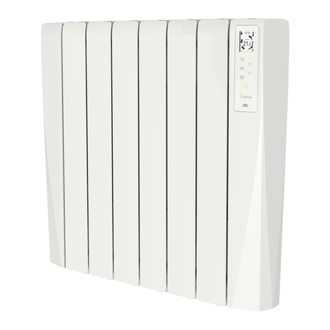
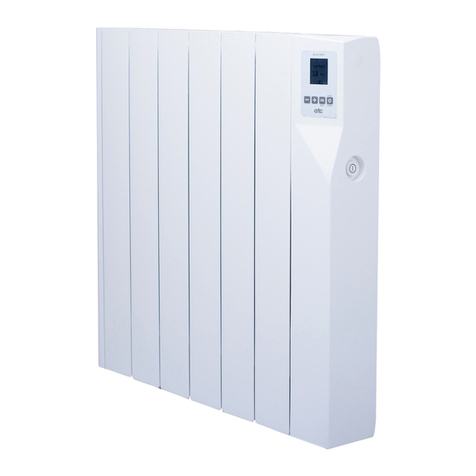
ATC VARENA 500 Technical manual

VARENA
Digital Electric Radiators – Daily and weekly programming
INSTRUCTIONS FOR USE & INSTALLATION
A7302
3342 – 2021-05


VARENA
A73023342 3
IMPORTANT:
- In order to avoid overheating, do not cover the heater.
The heater itself is mar ed with the standard
"Do not cover" symbol.
- You must not sit on the radiator.
- This appliance is not intended for outdoor use.
- If the power cord is damaged, it must be changed by the
manufacturer, its after-sales service or persons qualified to do
so, to avoid possible danger.
- The radiator should not be located underneath an electrical
connection. The electric supply line should be protected with
a high sensitivity differential device (RCBO).
- The radiator must be installed so that around it there is
sufficient space for proper circulation of hot air, with a
minimum distance of 100 mm to curtains, furniture, etc.
Anyone who is in the bathtub or shower should not have
access to the switches and other power operation devices.
Always eep at least 0.6 m between the radiator and the bath
or shower (UK: Outside zone 2, Ireland: Outside zone 3).
- Mounting is an important part of safety. To perform the
correct installation, go to Mounting section.
- This heating apparatus holds a specific amount of special
oil. Repairs where it is necessary to open the oil tan , must
only be made by the manufacturer or ATC. ATC should be
contacted in case of any oil lea age.

VARENA
4 A73023342
- A Fused Spur Switch must be included in the wiring to the
heater according to the wiring rules.
- This appliance can be used by children aged 8 years and
above and persons with reduced physical, sensory or mental
abilities or lac of experience and nowledge, if they have
been given supervision or appropriate training regarding the
use of the device in a safe way and they understand the
dangers involved. Children should not play with the appliance.
Cleaning and maintenance should not be performed by
unsupervised children.
- Children under 3 years should be ept out of reach of the
appliance unless they are constantly supervised.
- Children between age 3 and younger than 8 years old
should only turn on / off the device whenever it has been
placed or installed at its normal operating position provided
they are supervised or have received instructions concerning
using the appliance safely and understand the ris s
associated with the device. Children from 3 years and under
8 years old should not plug in, regulate, clean the appliance
or perform maintenance.
CAUTION - Some parts of this product can become hot
and cause burns. Pa particular attention when children
and vulnerable people are present.
- If the radiator is discarded, ensure it is recycled responsibly
and follow any local provisions concerning recycling of oil.
request.

VARENA
A73023342 5
This product is in conformit with the Directive 2012/19/EU.
The symbol of the “crossed-out wheelie bin” shown on the appliance indicates
that, at the end of its wor ing life, the product must be treated separately from
domestic waste and must be disposed of in a selective collection
centre for electrical and electronic appliances or must be returned to the
distributor upon purchasing an equivalent new appliance.
Users are responsible for disposing of appliances at the end of their wor ing life in established
collection centres. The correct collection of the appliance, allowing for the appliance to be
recycled at the end of its wor ing life, its treatment and its environment-friendly dismantling
help prevent any negative effects on the environment and on public health and favour the
recycling of the product components.
For more detailed information on the collection systems available, contact the local collection
facilities or the distributor where you made your purchase.
Pac ing List:
1x Varena Radiator
2x Metal Brac ets
2x Plastic Covers (top)
2x Loc ing Plastic Covers
4x Grey Wall plugs
4x Hex-Head Fixings
Please contact [email protected] if
any of the above are missing.
NOTE
A qualified electrician must carry out the electrical installation of
this radiator. The Electrical installation must comply with the
current UK and Irish regulations. Any claim on the warranty could
be invalid if these requirements have not been met
.

VARENA
6 A73023342
Contents
VARENA ...................................................................................................................................... 1
1.
INTRODUCTION .................................................................................................................. 7
2.
LOCATION ........................................................................................................................... 7
3.
ELECTRICAL CONNECTION ............................................................................................... 7
4.
MOUNTING .......................................................................................................................... 8
5.
OPERATION ....................................................................................................................... 10
5.1.
Control panel .......................................................................................................... 10
5.2.
Turning the radiator on and off ............................................................................... 11
5.3.
Operating modes .................................................................................................... 11
5.4.
Temperature display ............................................................................................... 13
5.5.
Edit day, time and program .................................................................................... 13
5.6.
Manual mode .......................................................................................................... 14
5.7.
Open Window function ........................................................................................... 15
5.8.
Adaptive Start control function ................................................................................ 15
5.9.
Keyboard loc ......................................................................................................... 16
6.
ERROR NOTIFICATIONS .................................................................................................. 16
7.
MAINTENANCE AND CARE .............................................................................................. 16
8.
CHARACTERISTICS TABLE .............................................................................................. 17
9.
ECODESIGN TABLE .......................................................................................................... 17
10.
WARRANTY ..................................................................................................................... 20

VARENA
A73023342 7
VARENA DIGITAL ELECTRIC RADIATORS
1. INTRODUCTION
Dear customer,
Than you for choosing ATC VARENA electric radiators, with their modern design, state-of-the-
art technology, great reliability and great quality construction.
ATC VARENA electric radiators and all their materials and components have passed strict
controls to ensure their quality.
Before installing and operating your heater, please read these instructions carefully as they will
ensure the correct wor ing order of the appliance features and ease of use. Keep them in a safe
place for future reference.
2. LOCATION
The radiator should be fitted in the part of the room where the client wants it, depending on the
space available, although preferably on or near outside walls, leaving enough space around the
heater for correct hot air circulation and at least 100 mm, from curtains and furniture, etc. The
distance should be at least 100 mm from the floor.
In bathrooms, the electric heater should be located outside of the protected area (Zone 1 & 2), as
indicated by Figure 1. Keep the fitting away from bath and showers.
Figure 1: Areas of the bathroom
3. ELECTRICAL CONNECTION
The Varena radiator must be connected to the mains supply (230 V ~ 50 Hz).
The maximum permissible impedance of the mains at the connection point will be:
Z
max
= 0.18 Ω.
It is required to install a switched spur for each heater. In addition, the following warnings must
be considered:
• The electric radiator should not be located underneath a light switch where ou need
to stretch over the heater to reach or operate the switch.
• The electric line should be protected with a high sensitivit differential device
(RCBO).
• It is necessar to de-energise or disconnect the power from the fixed wiring before
installation.
0,6 m
0,6 m
ZONE 1
ZONE 2
ZONE 3

VARENA
8 A73023342
Connecting wires:
Brown: Live
Blue: Neutral
Yellow-Green: Earth
The connecting wires must be of the appropriate cross section, with regard to the length of cable,
type of cable and power rating of the appliance.
The appliance must be connected into a fused connection box fitted with an appropriately sized
fuse for the radiator (see Characteristics Table on page 15). We recommend that the connecting
box is positioned 10 cm to the right of the appliance and 40 cm above the floor.
According to regulations, the appliance must be connected to the power supply by means of an
all-pole circuit brea er with a contact gap of at least 3 mm or by a thermal-magnetic circuit
brea er. It is recommended to install the heaters on a circuit protected by an RCBO.
4. MOUNTING
The electric radiator should be fixed to the wall by the adjustable brac ets supplied with the
radiator, using the cardboard template printed on the box.
If for any reason cardboard template is missing, you can follow the instructions below:
1. Place the two metal brac ets provided on the floor and against the wall as shown in image
1 below. Ensure the MB stamp on the metal brac et is at the top.
2. Chec Table 1 for the “A” distance between the brac ets for your VARENA model.
3. Mar the small hole in the metal brac ets on the wall with a pencil. These two mar ed
points determine the position of the two lower drill holes.
4. With the help of a level, position the brac ets matching their lower holes with the previously
mar ed points and mar the upper holes with the pencil.
1
Model A (mm)
VARENA 500 160
VARENA 750 240
VARENA 1000 320
VARENA 1200 400
VARENA 1500 400
VARENA 1800 720
Table
1

VARENA
A73023342 9
5. Drill the 4 mar ed holes. The grey plugs supplied require
an 8 mm hole.
6. Insert the grey plugs into the pre-drilled holes. Screw the
metal brac ets to the wall with the screws provided.
7. Attach the plastic pieces to the metal brac ets:
8. Hang the heater as shown:
3 4
STOP
5
2

VARENA
10 A73023342
TFT-LCD Screen
9. To detach the heater from the brac et:
5. OPERATION
5.1. Control panel
The control panel is composed of a large TFT-LCD screen with orange bac light and white images
for ease of legibility, and five eys as outlined below:
Standby key: switches the
radiator between Standby
and operational.
Exit Open Window ode
**The Standby key has a raised
bump to easily identify it by
touch.
Te perature, day, hour
Para eters selection
Keyboard lock
Edit day, ti e and progra
Selection of operating
ode
Confir day, ti e
Progra para eters
Copy the progra
Manual ode
1) Push the plastic
brac et away from
the metal brac et.
2) Lift the plastic
brac et and pull the
base of the heater
forward away from
the metal brac et.

VARENA
A73023342 11
5.2. Turning the radiator on and off
Once the radiator is connected to the power supply (230 V ~ 50 Hz), the
radiator is turned on by the switched spur; the standby icon or current
operating mode will appear on the display. It is turned off by the switched
spur.
If the radiator is in standby mode, to set it to operational, press the Standb ey. The screen will
light up and change from the standby screen to the previous operation mode.
To set it to Standby, press the Standb ey; the standby icon will appear on the screen and the
bac light will fade after 1.5 seconds. When the heater is in standby mode, if you press any ey
the standby screen will appear for 10 seconds. It is also possible to loc the radiator in Standby
mode (see Keyboard loc section of this manual).
The Standb ke is distinguished b its central position and the raised bump on its
surface. Use to switch the radiator between Standb and Operating mode.
In case of any power failure or disconnection, the radiator will always remember the previous
mode of operation, the temperature, and the state (Standby / operational and locked / unlocked .
If it is the first time that it is plugged in or has been disconnected for more than 4 da s, it will be
necessary to set the da and time again. If the disconnection is for less than 4 da s, the time
and da of the week will be saved.
Daily and wee ly programs are never lost even when disconnected from power for long periods.
5.3. Operating modes
By repeatedly pressing the mode ey the radiator is changed from one mode to another.
To identify the mode, a mode screen is displayed for 2 seconds.
COMFORT:
ECONOMY:
The first ode of operation that appears when the radiator is connected for the
first ti e, and changed fro Standby to operational, is "comfort".
In this ode, the desired roo te perature is selected by - and + keys, between
12 °C and 3 °C in steps of 0.5 °C (if the keys are held, the te perature changes
faster). When the te perature reaches either the axi u or ini u value it
will stop.
Typical co fort te perature is 20-21 °C. The co fort ode is nor ally used during
the hours the roo is o
ccupied.
The next ode that appears is "economy", which auto atically sets a te perature
between 0.5 °C and 4.5 °C less than the selected co fort te perature (the
difference can be directly set by the user with the - and + keys). When the co fort
te perature is raised or lowered, the ECO te perature auto atically rises or falls
by the sa e set a ount.
While the co fort te perature can be set fro 12 °C to 30 °C, the ECO
te perature is fro 7.5 °C to 29.5 °C, but always between 0.5 °C and 4.5 °C below
the co fort te perature.
MODE

VARENA
12 A73023342
ANTI-FROST:
PROGRAM:
CONFIGURATION:
To show the user that the radiator is heating there is a symbol of a thermometer being filled as
follows:
When the room temperature is below the temperature set point the radiator will turn the element
on to raise the room temperature.
In this ode, the te perature setting is 7 °C and is factory set.
Anti-frost is usually used as an off set point and for long periods
of absence when you want to avoid freezing.
In Program ode, the radiator auto atically switches between the 3 ode
te peratures according to the daily and weekly program set by the user.
The bar chart is displayed per anently and displays the 24-hour progra divided
into one-hour intervals.
Each one-hour interval can be progra ed as comfort, eco or heating off.
The bar showing the current ti e flashes to indicate to the user what the current
set point is.
Econo y ode is used for short absence periods to prevent the te perature
fro falling excessively.
The configuration screen is at the end of the odes sequence, before entering the
initial co fort ode.
You can configure 4 para eters; the active para eter is flashing:
1 – Screen backlight level at rest, from to maximum (1 %)
2 – Screen backlight ti e from 1 s to 24 s
3 - Open Window Function ON or OFF
4 - Adaptive start control function ON or OFF
To odify a para eter, use the - and + keys. To ove fro one para eter to the
next, press the OK key. The syste exits this ode by pressing the mode key at
any ti e, by waiting 30 seconds without pressing any key or by pressing the OK
key on the last para eter.
MODE
MODE
MODE

VARENA
A73023342 13
5.4. Temperature displa
The room temperature is normally displayed on the TFT display. The set point temperature is only
displayed when the user attempts to change it; after the setting has been adjusted the display will
revert to the room temperature:
The comfort and eco set point temperatures can be modified both from comfort and economy
modes. The comfort and eco mode can be changed within program mode if they are active at the
time (the anti-frost set point can never be modified).
5.5. Edit da , time and program
To edit the day, time and program, press and hold the mode ey for 2.5 seconds (from any mode)
until the cloc icon appears on the screen:
Editing of the day of the wee , time and program starts. This screen will also
be automatically displayed when the radiator loses the time after being
disconnected from the power supply for more than 4 days.
First, the day of the wee is selected with the - and + eys (indicated by a
flashing box). To confirm and set the day, press the OK ey and the radiator
now as s for the hour of the day by flashing the hour digits.
To change the hour, use the - and + eys. To confirm and set the hour, press
the OK ey. When the minute digits are flashing, change to the appropriate
time with the - and + eys and confirm by pressing the OK ey. The radiator
will now edit the program. *
Note: If the radiator had simply lost the time and day, it does not enter the
program, but returns to the last active mode
.
In the program editing screen, information about the selected interval and its set point temperature
are displayed at the top.
For example "PROG. D: 1 00h-01h" indicates day 1 of the wee and
hour from 00h to 01h.
"18.0 °C" indicates the set point temperature of day 1 from 00h to 01h,
which in this case is the eco set point. The "00h-01h" interval is flashing
to indicate that it can be modified with - and + eys.
At the bottom of the screen a 24 bar chart is displayed corresponding to one full day divided in
the 24 intervals of 1 hour. The bar of the selected interval has a small triangle just above it and is
flashing to indicate that it can be modified with the mode ey. The length of each bar indicates
the mode:
Tall bar= Comfort. Mid length bar = Econom . Short length bar = Heating off.

VARENA
14 A73023342
On the left axis of the bar chart are the 3 mode icons; the mode chosen for the interval being
programmed also flashes at the same time as the bar. To change the mode (comfort, economy,
Off) of each interval, press the mode ey. To move to the next or previous hour, press + or -
respectively.
By pressing the OK ey, the current program is saved and the program advances to the next day.
B pressing and holding the OK ke the program of the current da is copied to the next
da . After Day 7, when confirming with OK ey, the radiator exits the program edition, and returns
to the mode in which it was in prior to commencing editing the time and program.
To finish editing the program at any time you can press and hold the mode ey for 2.5 seconds.
5.6. Manual mode
The manual mode allows the user to manually operate the radiator and override the current
setting. It can boost the heater to heat (On) or not (Off) for a set amount of time. After the time
expires the radiator will return to the previous mode of operation.
The manual mode is designed to allow a user to override the Program mode
without having to change the program itself. For example, if you arrive when
the heater is normally unheated, you can heat the space to a comfortable
temperature, and then have the heater return to its normal mode without
changing the program.
To enter Manual mode press and hold the OK ey for 2.5 seconds, then using
the - and + eys enter the amount of time you want to force the radiator to heat
or not.
The editing is circular, from half an hour to 365 days; after 365 days the radiator
reverts to 00:30. The steps are:
- Half an hour from 00:30 to 12:00 hours
- 1 hour from 12:00 to 1 d
- 1 day from 1 d to 365 d
To confirm the time required, press the OK ey.
The desired temperature can then be set using the - and + eys; any
temperature between 7 °C to 30 °C (in steps of 0.5 ºC) can be entered.
Unheated mode (Off) can be entered from either 7 °C or 30 °C by entering - or
+ eys once from each extreme.
Unheated is indicated by the standby icon and 4 dashes on the screen (----). If
no ey is pressed within 30 seconds before final confirmation, the radiator will
return to the previous mode of operation.
When the desired temperature is entered confirm with the OK ey.
“ON” will be displayed.
The selected time will remain on the display and count down until it is finished,
and with the standby or sun icon depending on whether temperature set point
or unheated mode has been selected. The actual room temperature will be

VARENA
A73023342 15
shown when forcing the heating on. Although you cannot change the set time, it is possible to
change the set point temperature during the operation of manual mode using the - and + eys.
Once the set time has elapsed, the radiator will automatically return to the previous mode of
operation.
To exit manual mode at any time, press the OK ey. “OFF” will be displayed.
5.7. Open Window function
When the Open Window function is enabled in the configuration menu the
radiator automatically stops heating when it detects a sudden drop in
temperature (4 °C in 20 minutes). This is normally caused when a window or
door is opened to the outside without turning off the radiator.
When the Open Window function has been activated it is indicated on the display by a single
screen with an open window. In order to enable the heating again the user must press the
Standb ey. The radiator will then return to the previous mode of operation.
Note: In installations where this function is activated very frequently, it may be appropriate to eep
it disabled.
* This function is considered b Directive 2009/125/EC regulations and will give the unit
more efficienc during operation.
5.8. Adaptive Start control function
When the Adaptive Start control function is enabled in the configuration
menu, the radiator automatically starts heating prior to the
programmed time (a maximum of 2 hours before), to ensure that the
next “on” set point is at the required temperature on time.
The radiator analyses the next two hours, and if there is a set point
higher than the current room temperature within that time period, and
nowing the heating speed of the unit, the software calculates when it
needs to start heating. This calculation is made each 5 minutes.
This function only runs when the radiator is in Program mode. When Adaptive Start is running, a
flashing cloc icon is displayed next to the thermometer symbol. The function will only run on
temperature rise e.g. from heating off to eco / comfort, or from eco to comfort.
When Adaptive Start is running the radiator progressively increases the set point temperature
until the next programmed set point is reached.
* This function is considered b Directive 2009/125/EC regulations and will give the unit
more efficienc during operation.

VARENA
16 A73023342
5.9. Ke board lock
The user can loc the eyboard on the Varena radiator by pressing and holding the - and + eys
for 2.5 seconds. The unloc is performed in the same way. When the eypad is unloc ed or
loc ed, the screens are displayed:
This is possible in all modes of operation except in Configuration. The radiator can be also loc ed
when is on Standby. When the radiator is loc ed, the padloc icon will appear in the upper left
area of the screen:
6. ERROR NOTIFICATIONS
There are 3 types of errors that the electronics can detect; if an error is detected one of the codes
below will be displayed on the screen until it is resolved:
ERROR CODE DESCRIPTION
ERROR1 Failure in microcontroller or RTC ( roblems with the current time)
ERROR2 Failure of the NTC tem erature robe (e.g. disconnected, short-circuited, etc.)
ERROR3 Failure of the EPROM memory
When recovering from an error, the radiator will always go to Standby mode; the radiator will not
retain any previous mode or state.
If the radiator goes to Standby without any specific reason, it may have recovered from an error.
7. MAINTENANCE AND CARE
The Varena radiators require very little maintenance.
The surfaces of the radiator must not be cleaned with an abrasive product or those containing
granular substances. We recommend regular cleaning with PH neutral products.
In order to clean the radiator, it is recommended that the electric power is switched off.
Failure to eep the Varena radiators clean may result in dust becoming burnt and depositing on
the wall above the heater in the form of dar strea s or patches. This type of mar ing is expressly
due to failure to eep the heater and surrounding area clean.
ATC take no responsibilit for an such damage caused.

VARENA
A73023342 17
8. CHARACTERISTICS TABLE
Model
No.
elements
Power
(W)
A
(mm)
Wei ht
(k )
Volta e
Class
Index of
protection
Type of
radiator
VARENA 500 3 500 335 6
230 V ~
50 Hz I IP2X FLUID
VARENA 750 5 750 495 8.7
VARENA 1000
6 1000 575 10.1
VARENA 1200 7 1200 655 11.6
VARENA 1500
9 1500 815 14.2
VARENA 1800 13 1800 1135 19.8
A
100
581
9. ECODESIGN TABLE
Models VARENA
500
VARENA
750
VARENA
1000
VARENA
1200
VARENA
1500
VARENA
1800
Heat output
Nominal heat out ut (P
nom
) 0,5 kW 0,8 kW 1,0 kW 1,2 kW 1,5 kW 1,8 kW
Maximum continuous heat out ut (P
max,c
) 0,5 kW 0,75 kW 1,0 kW 1,2 kW 1,5 kW 1,8 kW
Auxiliary electricity consumption
At nominal heat out ut (el
max
) 0,000 kW 0,000 kW 0,000 kW 0,000 kW 0,000 kW 0,000 kW
At minimum heat out ut (el
min
) 0,000 kW 0,000 kW 0,000 kW 0,000 kW 0,000 kW 0,000 kW
In standby mode (el
SB
) 0,0013 kW
Type of heat output/room temperature control Electronic room tem erature control lus week timer
Other control options
Room tem erature control, with o en window detection
With ada tive start control
ATC Electrical & Mechanical
ATC House, Broomhill Drive, Tallaght, D24 EF99, IRELAND
T: 00 353 1 4678 301 UK T: 0203 564 9164
F: 00 353 1 4520 887
Email:
sales@atc.ie

VARENA
18 A73023342
NOTES
_________________________________________________________________
_________________________________________________________________
_________________________________________________________________
_________________________________________________________________
_________________________________________________________________
_________________________________________________________________
_________________________________________________________________
_________________________________________________________________
_________________________________________________________________
_________________________________________________________________
_________________________________________________________________
_________________________________________________________________
_________________________________________________________________
_________________________________________________________________
_________________________________________________________________
_________________________________________________________________
_________________________________________________________________
_________________________________________________________________
_________________________________________________________________
_________________________________________________________________
_________________________________________________________________
_________________________________________________________________
_________________________________________________________________
_________________________________________________________________
_________________________________________________________________
_________________________________________________________________
_________________________________________________________________
_________________________________________________________________
_________________________________________________________________
_________________________________________________________________
_________________________________________________________________
_________________________________________________________________
_________________________________________________________________
_________________________________________________________________
_______________________________________________________________

A73023342 19

20 A73023342
10. WARRANTY
www.atc.ie www.atcelec.co.u
IE: 0353 1 467 8302 UK: 0044 0203 564 9164
MADE IN SPAIN
USER SELLER
Name Name
Address Address
Date of sale Stamp and signature of the distributor
WARRANTY CERTIFICATE
GUARANTEE: ATC with address ATC House, Broomhill Drive, Tallaght, D24 EF99 Dublin, IRELAND
PRODUCT: This warranty is applicable to the products contained in this manual.
WARRANTY: 24 months from Date of Purchase (Proof of sale required)
ATC assures the electronics in the control panel have a warranty of 2 years from the date of purchase.
ATC assures the aluminium elements that ma e up the heater body are guaranteed for 10 years. There are excluded in this
period the other components.
Unless proven otherwise, it shall be presumed th at if not shown within six months of delivery that the product was fine when
delivered.
There is a parts warranty of two years from the date of delivery of the appliance, apart from the aluminium frame which is
guaranteed for 10 years.
This warranty applies, only and exclusively, to equipment sold and installed in Ireland and the United Kingdom.
Repairs will be carried out in the wor shops of ATC or its nominated agent.
The material replaced in warranty becomes property of ATC.
SCOPE OF WARRANTY
Unless there are event(s) or object(s) that prove to the opposite, it will be assumed that the products acquired are suitable and
good for the purpose that they are purchased for and that always happens
under the following conditions:
- The guaranteed unit shall correspond to the manufacturer intended exclusively for Ireland and the United Kingdom and should
be installed in Ireland and the United Kingdom.
- The spare parts which are necessary to replaced, will be determined by our qualified service and in all cases, shall be original
products from the manufacturer.
- The warranty is valid provided that normal maintenance operations described above in the instructions provided with the
equipment have been carried out.
- The consumer must inform ATC of the lac of conformity of the goods, in a period of less than two months of them learning of it.
The warrant does not cover incidents caused b :
- The power supply of insufficient capacity or equipment with generators or any other system that is not a stable power supply.
- Products whose repairs have not been conducted by ATC qualified service personnel or their authorised agents.
- Corrosion, deformation, etc., caused by improper storage.
- Handling of the product by other personnel not employed by ATC during the warranty period.
- Installation not in accordance with the instructions provided with the equipment.
- Installation of equipment by unqualified personnel.
- Defects in electrical, hydraulic facilities, or by lac of flow, etc.
- Defects caused by improper treatment.
- Anomalies caused by atmospheric agents (ice, lightning, flooding, etc.) as well as erratic current or voltages.
- Improper maintenance, neglect or misuse.
- Damages caused to premises caused by lac of cleaning of the radiator (blac strea s on walls).
Transport damages must be claimed b the user directl from the carrier.
VERY IMPORTANT: Radiators must be correctl sized for each room the are to heat. There is sizing information available
on the website www.ATC.ie.
Draught and badl insulated rooms will cause the radiator to use more power to reach the set temperature. Undersized
radiators ma not reach the set temperature and are costl to run.
To claim on the warranty here recognized, it will be required that the appliance is used as intended for household and commercial
use only. Also, it will be necessary to deliver the radiator to the technical personnel of ATC at their premises or the premises of
their nominated agent. A clear and legible copy of the invoice or receipt for the radiator together with the delivery slip must be
supplied.
Note: All our technical assistance service officers have the corresponding accreditation by ATC.
A7302
3342 – 2021-05
This manual suits for next models
5
Table of contents
Other ATC Heater manuals

ATC
ATC Alfresco ALH1800 Instruction manual
ATC
ATC PH1000T User manual

ATC
ATC Sun Ray RF Series User manual

ATC
ATC Lifestyle User manual

ATC
ATC iLifestyle WLS1800 User manual

ATC
ATC iLifestyle User manual

ATC
ATC iLifestyle User manual
ATC
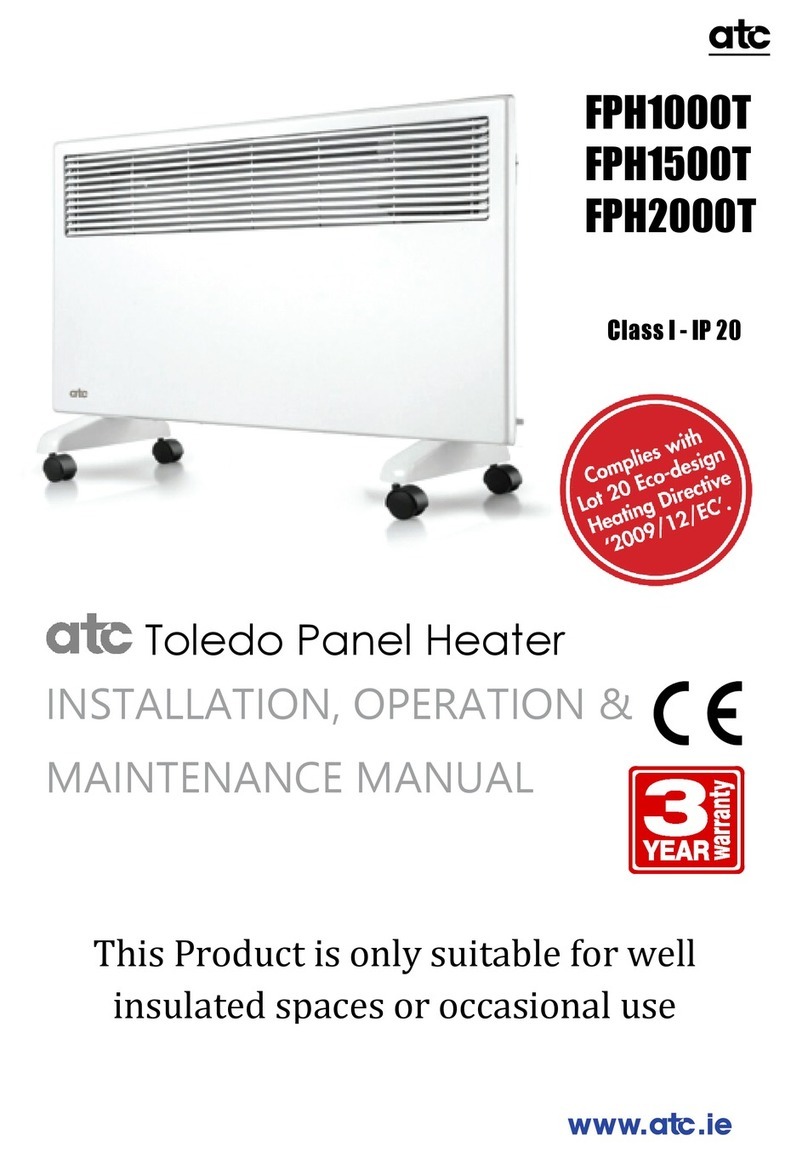
ATC Toledo FPH1000T Instruction manual

ATC
ATC LIFESTYLE 500 Technical manual

ATC
ATC Smart Merida RF User manual