ATC ATC-2000WF User manual

QuickStart Guide
Wi-FiTO RS-232/422/485
CONVERTER
MODELATC-2000WF
(Version 2.0)
1
1
1.Check Package Content
ATC-2000WF unit 1Pcs
RS-232DB9Female Crossing configuration cable
1Pcs
monopole Antenna (2dBi RP-SMA) 1Pcs
Software CD 1Pcs
Ext power adapter1Pcs
Printedversionof thisATC-2000WF QuickStart Guide
1Pcs
2
2.HardwareInstallation
Connect RS-232DB9Female Crossing configuration cable
toATC-2000WF unit on RS-232side.
Connectingthe Power Adapter to ATC-2000WF power jack.
Whenthe power isproperly supplied. The Link LED will
contioustoflashand PWR LED will light inredwhensystem
isready.
RS-232/422/485 Pinouts
RS-232Pinout(DB9 Female )
PIN RS-232Input/Output
2RXD I
3TXD O
5GND -
7RTS O
8CTS I
RS-422/485 Pinout(SIX Terminal from Left)
PIN RS-422RS-485
1T+ 485+
2T-485-
3R+ NC
4R- NC
5VIN+VIN+
6VIN- VIN+
3
3.LED indication
LINK ---- IndicateWLAN status
DIS ---- IndicateWLAN status
ACT ----It will flashwhen transmit thedatafromWLAN to
serial or from serial toWLAN.
PWR ----Indicate thePower supply
Detail for LINK,DIS Led indicate
LINK DIS Status
ON solidNotAssociated
Connectedover TCP
Fast Blink- No IP Address(enter
Command mode)
Slow Blink Associated,
NoInternet IP AddressOK
4
4.SoftwareInstallation
Insert the software CD andsearchforsuchasF:/Tool/
pcommlite folder torun Settup.exe.Note: Besureyou have
administrative rights &disable firewalls in windowsXP
5
5.Configure the ATC-2000WF
Serial Console (9600, n, 8, 1)
Before configuringthe ATC-2000WF viathe serial console,
turnoff thepoweranduse a serial cable to connect the
ATC-2000WF toyour computer sserial port. We suggest
usingPCommTerminal Emulator, which isavailableinCD
driverto carryout theconfigurationprocedure. Firstlyinstall
PCommTerminal Emulatoron your computer.
Connect ATC-2000WF RS-232serial port directly to your
computer smale RS-232serial Port with RS-232DB9Female
CrossConfigurationcable
FromtheWindowsdesktop, clickon Start # Programs #
PComm Lite # Terminal Emulator.
Whenthe PComm Terminal Emulator window opens,
firstclickonthe PortManager menuitemand select Open,
orclickon the Open icon.
The Property window opensautomatically. Fromthe
Communication Parameter page,
select the appropriate COM port for the connection, COM1 in
thisexample, and 9600 for
BaudRate, 8 for DataBits, None for Parity, and 1 for Stop
Bits.

Fromthe Property window.s Terminal page, select ANSI
or VT100 for Terminal Type,andclickon OK. If youselect
Dumb Terminal asthe terminal type, someof the console
functions—especially the.Monitor. function—maynot work
properly.
Uponpowerup, the devicewill bein datamode. Toenter
commandmode, exactlythe three characters $$$ mustbe
sent. Thedevice will respond with CMD.
While incommandmode,thedevicewill accept ASCII bytes
ascommand. Toexit commandmode,send exit<cr>. The
device will respond with “EXIT”todatamode.
Parameters,such asthe SSID, channel, IP address, Serial
Portsettings,and all othersettings canbe viewedand
configuredin commandmode. ASCII characters canbesent
throughaterminal emulator connectedtotheUART orvia
Telnet. When usingthe UARTcommunicationssettings
should matchthe settingsused when ATC-2000WF connects.
for example:thedefault is9600 baudrate,8bits,NoParity, 1
stopbit, andhardwareflow control disabled.
Start by configuring theIP address and WLAN under
MS-DOS Command Mode. section for instructionsonhow to
configure therest of theIP settings.
Choosing theProperOperation Mode
6
6.FactoryDefaultWLAN &IP Address
Default Configuration Settings
COMM Parameters
Close string: *OPEN*
Openstring:*CLOS*
Remote string:*HELLO*
FlushSize:16
MatchByte : 0
FlushTimer:2
IdleTimer:0
IP Parameters
DHCP: 1(enabled)
Protocol: TCP-Server
Address:0.0.0.0
Local port:2000
Net Mask: 255.255.255.0
Gateway: 0.0.0.0
Host: 0.0.0.0
Remote port: 2000
Ftp 208.109.78.34( rovingdefault updateserver )
(port fixedat 21)
System Parameters
Sleep timer:0
Waketimer:0
Trigger: 1(SENS0pin wakesup thedevice)
Autoconnect: 0
IOMask:0xFC( 3,4,5,6,7,8 outputs).
Print Level: 1(printsenabled)
Time Server Parameters
Enable: 0= disabled
Address: 158.152.1.76
Port: 37( NIST TIME protocol )
Zone: 7(PacificUSAtime)
UARTParameters
Baudrate:9600
Parity:n(none)
Flow :0=disabled
WLAN Parameters
Channel: 0Mode:infrastructure
SSID: roving1:Rate: 1(1=1Mbit)
7
7.Summaryof Commands
(These commandsare explainedmore detailed functioning
inCD ATC-2000WFCommand Reference.)

ATC-2000WF CommandReference
(Version 2.0)
1.0 Configuration
1.1 Entering Command Mode
Upon power up, the device will be in data mode. To
enter command mode,exactlythe three characters $$$
must be sent. The device will respond with CMD.
While in commandmode, the device will acceptASCII
bytesascommands.Toexitcommand mode, send
exit<cr>. The device will respond with “EXIT”.
Parameters,suchasthe SSID, channel, IPaddress,
Serial Port settings,andallothersettingscan be
viewed and configured in command mode. ASCII
characters can be sent through aterminal emulator
connectedto the UART or via Telnet. When using the
UART communicationssettings should match the
settings used when ATC-2000WF connects,
for example: the default is 9600 baudrate ,8 bits, No
Parity,1stop bit, and hardware flow control
disabled.
Run your favorite terminal emulator, You can find on
CD/tool/pcommlite.
Type $$$ on your terminal emulator.You should see
“CMD”returned to you. This will verifythat yourcable
and comm. settings are correct. Mostvalid commands
will returnan “AOK”,response, and invalid ones will
return an”ERR”description.
To exit command mode, type exit <cr>.
NOTE: Youcan entercommand mode locallyoverthe
serial port at anytime when not connected, and also
when connected if the appropriatesettings are enabled.
Remote configuration using ADHOC mode
Using adhoc mode to configure the device eliminates
the need forthe module to be associated with a
networkaccesspoint. In adhocmode the module
createsit own “on demand”networkthat you can
connect to via your computer likeyou would to any
other network.
To enable adhocmode via hardware set innerSW1
DIP1 to ON(Default isOFF).(You should open the
ATC-2000WF metal case).The module will creates an
adhoc networkwith the following
SSID: WiFly-GSX-XXwhere XX is the final two bytesof
the devicesMAC address
Channel: 1
DHCP: OFF
IP address: 169.254.1.1
Netmask: 255.255.0.0
From yourcomputer, connect to the WiFly-GSX-XX
network. This is an open networkwhich does
not requirea passphrase or pass key. Note: currently
the WiFlyonlysupports OPEN mode for
creatingadhoc networks.
NOTE: It maytake a couple of minutes for Auto IP in
Windowsto assign an IPaddress and connect
to the network. You can checkIPaddressof your
Windowscomputer byrunning the ipconfig
command in the command window. If connected,this
command will show you the IPaddress and net
maskfor your computer.
The IPaddressassigned byAuto IPmust be on the
subnet 169.254.1.X otherwise the WiFlyGSX
module will not be accessible.
NOTE: If your machine hasbotha wireless and wired
interface hardware you will need to disable the
wired LAN interfacehardware before connecting to the
adhocnetwork. If the wired LAN is enabled
the computerwillassign anIP addressthat is not on
the samesubnet asthe WiFlymodule.
Once connected and you have a good IPaddress,
telnet into the WiFlymodule on port 2000
telnet 169.254.1.1 2000
You should see the response “*HELLO*”
You can now enter command mode and configure the
module.
2.0 ATC-2000WF Command Reference
2.1 Command Syntax
Commandsbegin with akeyword, and have optional
additionalparameters,generallyspace delimited.
Commandsand options are case sensitive. Hexinput
data can be upper or lowercase. String textdata, such
as SSID is also case sensitive.
The firstcommand is fullydecoded and must be
complete. Other command parameters can be shorted
byusing onlythe firstcharacter.
For example,
setuart baudrate 115200 is valid,
setuart b 115200 is also valid,
setu b 115200 is alsovalid, however,

suartbaudrate 115200 isNOT valid.
Numberscan be entered as eitherdecimal, (like
115200 above) or HEX.To enter HEX, use 0x<value>.
For example, the HEXvalue FFwould be entered as
0xFF.
2.2 Command Organization
Commandsfall into 5 general categories:
·SET COMMANDS -Take effect immediately,
permanently(save command issued).
·GET COMMANDS -Retrieve the permanentlystored
information for displayto user.
·STATUSCOMMANDS -See what isgoing on with the
interface, IPstatus, etc.
·ACTION COMMANDS- Perform action suchas scan,
connect, disconnect, etc.
·FILE IO COMMANDS - Upgrade, load and save
configuration, delete files, etc.
NOTE: You mustsave the configuration orthe
module willload the previous settingsupon reboot or
power up.
When the system boots, all configuration data is loaded
into RAM variables from the file called “config”.The
set commandsactuallyonlymodifythe RAMcopyof
variablesin the system. This allowstemporary
change ofparameters “on the fly”to test features,
minimizespower usage and saves on flash re-write
cycles.
Once all configurationiscomplete, the usermustsave
the settings usingthe save command to storethe
configuration data,otherwiseit will nottakeeffectupon
reboot or reset. Multiple configurations can be stored
byusing the save<filename> command, and these
configurationscan be loaded using the load
<filename> command. Thesefilescan be upload to
remote FTPsite, such that once adesired configuration
is created, it can quickly be copied into additional
devices(cloning).
3.0 SET Commands
These commands begin with “set”.Thereare 6 major
categories.
·ADHOC -controls the adhocparameters
·BROADCAST - controls the broadcasthello/heartbeat
UDP message
·COMM -communication and data transfer, timers,
matching characters
·DNS -DNS host and domain
·FTP -FTPhost address and login information
·IP -IPsettings
·OPTION - optional and notfrequentlyused parameters
·SYS -systemsettings such assleep and wake
timers
·TIME -timer serversettings
·UART -serial portsettings such as baudrate and
parity
·WLAN- wirelessinterface settings, suchas ssid,
chan, securityoptions
3.1 ADHOC Parameters
set adhoc beacon <ms>
setsthe adhoc beacon interval in miliseconds. Default
is 100.
set adhoc probe <num> setsthe adhocprobe retry
count. Default is 5. Thisisthe numberof consecutive
probe responsesthat can be lost before declaring.
“ADHOC islost”and disabling the network interface.
3.2 BROADCAST Parameters
setbroadcast address <addr>
sets the address to which the UDPhello/heartbeat
message issent. The default addressis
255.255.255.255
setbroadcast interval <value>
sets the interval at which the hello/heartbeat UDP
message issent. Interval isspecified in seconds. The
value is a maskthat is compared to a free running
seconds counter. For example if interval= 0x7, a packet
will be sent every8 seconds.The minimuminterval
value is 0x01 (every2 seconds)and maxvalue is 0xff
(every256 seconds).Setting the value to zero turns off
the UDP broadcast. The default intervalis7.
setbroadcast port <port>
sets the port number to which the UDP hello/heartbeat
message issent. The defaultport is55555.
3.3 COMM Parameters
setcomm close <string>
sets the ASCI string that issent to the local UART
when the TCPport isclosed. If no string isdesired, use
0 asthe <string> parameter. Maxstringlength is 32
characters. Defaultis *CLOS*
setcomm open <string>
sets the string that issent to the local UART when the
TCP port is opened. If no string is desired, use 0 asthe
<string> parameter.Max string length is32 characters.
Default is *OPEN*
setcomm remote <string>
sets the string that issent to the remote TCP client
when the TCPport isopened. Ifno string is desired,

use 0 as the <string> parameter. Max string length is
32 characters. Default is *HELLO*
setcomm idle <secs>
sets the Idle TimerValue. This isthe number of
seconds with notransmit or receivedata before the
connection is closed automatically.Default is 0, never
disconnecton idle.
setcomm match <value>
sets matching character initiateforwarding data across
the TCP/IPconnection. The value isentered asthe
decimal value of the of the ASCII character.Default is 0,
disabled. For more information see section 1错误!未找
到引用源。.4
setcomm size <value>
sets the Flush Size value. This isthe number of bytes
to receive on the UART before forwarding. 0 disables
forwarding based on byte count.Default is64 bytes(at
9600). Maximum value = 1420 bytes.
NOTE: This value isset automaticallywhen the
baudrate isset, in an attempt to optimize the link. It is
assumed that higherbaudrates suggest larger buffer
sizes and hence the size will increase at higher
baudrate settings.
setcomm time <num>
sets the Flush Timer.Thisisthe numberof 1
millisecond intervalsafterthe last UART byte is
received before the data is sent over Wifi.1 isthe
minimum value.Default is 10 (10 milliseconds). Setting
thisvalue to 0 will disable forwarding based on time
delay.
3.4 DNSParameters
setdns address <addr>
setsthe IPaddressof the DNS sever.This isauto-set
when usingDHCP,and needsto be set in STATIC IP
or Auto-IP modes.
set dns name <string>
setsthe name of the host for TCP/IP connections.
set dns backup <string>
setsthe name of the backup host forTCP/IP
connections.
3.5 FTPParameters
set ftp filename <file>
setsthe name of the file transferred when issuing the
“ftp u”or “ftp g”commands.
set ftp addr <addr>
setsthe ftp server IP address.
set ftp remote <port>
setsthe ftpserverremote port number (default is 21).
set ftp user <name>
setsthe ftp user name for accessing the FTPserver.
set ftp pass <pass>
setsthe ftp password for accessing the FTPserver.
3.6 IPParameters
set ip address <addr>
setsthe IPaddress of the ATC-2000WF.If DHCPis
turned on, the IPaddress isassigned and overwritten
during association with the access point.IPaddresses
are “.”delimited.
Example: set ip a 192.168.1.10”
set ip backup <addr>
setsa secondaryhostIPaddress.
set ip dchp <0,1>
e enable/disable DHCP mode. Ifenabled, the IP
address, gateway,netmask, and DNSserver are
requested and set upon association with access point.
Anycurrent IPvaluesare overwritten.DHCP Cache
mode can reduce the time it takes the module to wake
from deep sleep thussaving power. In cache mode, the
lease time ischecked and if not expired the module
usesthe previous IP settings. If the lease hasexpired
the module will attempt to associated and use DHCPto
get the IP settings. DHCP cached IPaddressdoesnot
survive a power cycle or reset.
the default setting )
setip flags <value>
Set IPrelated advancedfunctions. Valueis a bit
mapped flag register. Default = 0x7.
Bit
Value
Protocol
0 DHCP OFF, use stored staticIP address
1 DHCP ON, get IPaddress and gateway
from AP
2 Secure (onlyreceive packets with IP
address matchesthe store host IP)
3
DHCP cache mode,Uses previous IP
address if lease isnot expired (lease
survives reboot)
4 Reserved forfuture use

setip gateway <addr>
sets the gatewayIPaddress,If DHCPis turned on, the
gatewayIPaddress is assign and overwritten during
association with the access point.
setip host <addr>
sets the remote hostIP address.This command is
used for making connectionsfrom the ATC-2000WEto
a TCP/IPserverattheIPaddress<addr>.
setip localport <num>
sets the local port number.
setip netmask <value>
sets the networkmask.IfDHCPis turned on, the net
maskis assign and overwrittenduring association with
the accesspoint.
setip protocol <value>
sets the IPprotocol. Value is a bitmapped setting.To
connect to the ATC-2000WF module overTCP/IPsuch
as Telnet the device must havethe use the TCP Server
protocol / bit 2 set. To accept both TCP and UDPuse
value = 3 (bit 1 and bit 2 set)
setip remote <value>
sets the remote host port number.
3.7 OPTIONAL Parameters
setopt jointmr <msecs>
Join timer isthe time in milliseconds (default=1000) the
join function willwait for thean accesspoint to
complete the association process.This timer isalso the
timeout for the WPA handshaking process.
set opt replace <char>
replacement characterfor spaces. The replacement
characteris used when entering SSID and pass
phrasesthat include space.This is used bythe
ATC-2000WFcommand parser only.Each occurrence
of the replacement characterischanged into a space.
The default is “$”(0x24)
set opt deviceid <string>
Configurable DeviceID - can be used for storing serial
numbers,productname or other device information.
This information is sent aspart of the broadcast hello
packet that is sent asa UDP.The current valuecan be
shown with the “get option”or “show deviceid”
commands. Max string size is32 bytes. The default is
“WiFly-GSX”.
set opt password <string>
TCPconnection password. Used to challenge the
remote device to authenticate the connection. When
set all incoming connections will bechallenged and the
first characterssent must match the stored password or
the connection will be closed. When the password is
set the WiFlymodule willsend the string “PASS?”to
the remoteconnection. All characters in the string must
be sentin one TCPpacket. Maxstring sizeis32 bytes.
To disable the password feature use string=0which is
the default.
3.8 SYSTEM Parameters
set sys autoconn <secs>
TCPmode: setsthe autoconnect timer.This command
causesthe module periodicallyconnect to the host.
The timer <secs> determineshowoften to connect to
the stored remote host. If set to 1, the module will only
make one attempt to auto connect uponpower up. If set
to 2 orgreaterauto connect will re-openthe connection
after the connection isclosed. Default=0 disables.
setsys autosleep <num *10ms>
Sets the auto-sleep timer. 0 disables. If the protocol is
set to UDP ONLY, thistimeris used as a quicksleep
function. Device will sleep <num> ms after transmission
of the first UDP packet.
setsys iofunc <value>
sets the IO portalternate functions.Bit-mapped value.
For
more details see section 10.5
setsys mask <mask>
sets the IO port direction mask.Bit-mapped value. For
more information see section 1错误!未找到引用源。.5
setsys printlvl<value>
sets numerousprint functions.0=quiet 1=connect
information Defaultis 1.
setsys output <value> <mask>
sets output PIOpins to HIGH orLOW.
Bit-mapped value. Optional maskonlysetsa subset of
pins.
Bit
Function
0 TCP stackcopies RX bufferbefore
sending
1 BypassNagle algorithm and use
TCP_NODELAY
2 TCP application level single retryenabled
3 RETRY multi -retries4 times
4 DNShost addresscaching enabled
5 ARPtable caching enabled
6 Reserved
Bit
Value
Protocol
0 UDP
1 TCP Server &Client (Default)
2 Secure (onlyreceive packetswith IP
addressmatchesthe store host IP)
3 TCPClientonly
4 Future Use

setsys sleep <secs>
sets the sleep timer.0 disables.
NOTE: If not using Sensor pinsto wakethe module, be
sure to set the waketimer beforeissuing the sleep
timer orthe module will not wakeup. See section 8.1
for more details on using system timers
setsys trigger<value>
sets the sensor input(s) to wake on (1-4). Bit-mapped
value. 0 disables.
setsys wake <secs>
sets the auto wake timer. 0 disables. See section 错误!
未找到引用源。 formore details on using system timers
3.9 TIMEServer Parameters
settime address <addr>
sets the time server address. (SNTPservers)
settime port <num>
sets the time server port number.Defaultsto 123 which
isalmostalwaystheSNTP serverport.
settime enable <value>
Enable or disable fetching time from the specified sNTP
time server.Default=0= disabled. A value or 1 gets time
onlyonce on powerup. Anyvalue >1 gets time
continuouslyevery<value>minutes.
3.10 UART Parameters
setuart baud <rate>
set the UART baud rate. Valid settings are {2400, 4800,
9600,19200, 38400, 57600,115200, 230400, 460800,
921600}.
Example : “set u b 9600”sets the baud rate to 9600
baud.
setuart instant <rate>
This immediatelychanges the baudrate. This is useful
when testing baudrate settings, or switching baudrate
“on the fly”remotelywhile connected over TCP. This
setting does not affectconfiguration.Returns the AOK
response, and thenthis command will exit
command mode.
set uart raw<rate>
setsa RAWUART value. Used to setnon-standard
rates. The lowest possiblebaud rate is 2400.
Example : “set u r 7200”sets the baud rate to 7200
baud.
set uart flow<0,1>
setsthe flowcontrol mode. Default=0=off, 1= hardware
RTS/CTS.
NOTE: once flowcontrol is enabled, it is importantto
properlyDrive the CTSpin (active LOWenabled) If
CTSisHIGH, data will NOT be sentoutthe UART, and
further configuration in command mode will be
problematic as no response will be received.
set uart mode<value>
setsthe UART mode register. This is a bit-mapped
value.
set uart tx <0, 1>
Disablesor enables the TX pin= PIO10 of the UART.
Disable willset PIO10 to an INPUT with weak
pulldown.
NOTE:Due to an issue in the UART hardware, the
UART does not support even or odd, parity.
4.11 WLAN Parameters
setwlan auth <value>
Sets the authentication mode. Not needed unless using
auto join mode 2. i.e. set wlan join 2
Note: During association the WiFlymodule interrogates
the Access Point and automaticallyselects the
authentication mode.The current release of 2000WF
firmware supportsthese securitymodes:
•WEP-128 (open mode only, NOT shared mode)
•WPA2-PSK (AES only)
•WPA1-PSK (TKIP only)
•WPA-PSK mixed mode (some APs,not all are
supported)
setwlan channel <value>
sets the wlan channel, 1-13 is the valid range fora
fixed channel.If 0 is set, then scan is performed, using
the ssid, for all the channels set in the channelmask.
setwlan ext_antenna <0, 1>
determineswhich antenna is active, use0 for chip
antenna, 1 for UF.L connector. Default = 0. Onlyone
antenna is active at a time and the module must be
power cycled after switching the antenna.
Bit
Value
Function
0 NO ECHO - disables echo of RXdata
while in command mode
1 Reserved for future RAWmode protocol
2 Reserved for futureRAWmode protocol
3 Enable Sleep on RX BREAK signal
Value
Authentication Mode
0 Open (Default)
1 WEP-128
2 WPA1
3 Mixed WPA1 &WPA2-PSK
4 WPA2-PSK
5 Not Used
6 Adhoc, Join anyAdhocnetwork

setwlan join <value>
sets the policyfor automaticallyjoining/associating with
networkaccess points. Thispolicyis used when the
module powers up,including wake up fromthe sleep
timer.
setwlan hide <0, 1>
Hidesthe WEP keyand WPApassphrase. When set,
displaying the wlan settings shows ****** for these
fields. To unhide the passphraseorpasskey, re-enter
the keyor passphrase using the set wlan keyor set
wlan passphrasecommand. Default = 0, don t hide.
wlan key <value>
sets the 128 bit WEP key. Ifyou are using WPA or
WPA2 you should enter a passphrase with the set
wlan passphase command. Keymust be EXACTLY13
bytes (26 ASCII chars).Dataisexpected in HEXformat,
“0x”should NOT be used here.
Example : “set w k112233445566778899AABBCCDD”
Hex digits > 9 can be eitherupperorlower case.
The ATC-2000WF onlysupports “open”keymode, 128
bit keys for WEP.WEP-128, shared mode is not
supported as it is known to be easilycompromised and
has been deprecated from the Wi-Fi standards.
set wlan linkmon <value>
setsthe linkmonitor timeout threshold. If set to 1 or
more, ATC-2000WFwill scan once persecond for the
AP it isassociated with.The value is the threshold of
failed scansbefore the ATC-2000WF declares “APis
Lost”,de-authenticates. TheATC-2000WFwill retrythe
association based on the join policyvariable. A value of
5 is recommended, assome APs will not always
respond to probes. Default is 0 (disabled). Without this
feature, there is no wayto detect an AP is no longer
present until it becomes available again (if ever).
set wlan mask <value>
setsthe wlan channel maskused forscanning
channelswith the auto-join policy1 or 2,used when the
channel isset to 0. Value isa bit-map where bit 0 =
channel 1. Input forthis command can be entered in
decimal or hex if prefixed with 0x. Default value is
0x1FFF (all channels)
set wlan num <value>
setsthe default WEP keyto use. 1-4 is the validrange.
Example : “set w n 2”sets the default keyto 2.
set wlan phrase <string>
setsthe passphrase forWPA and WPA2 security
modes.1-64 chars.The passphrase can be alpha and
numeric, and is used along with the SSID to generate a
unique 32 byte Pre-shared key(PSK), whichis then
hashedinto a 256 bit number. Changing either the
SSID or thisvalue re-calculatesand storesthe PSK.
If exactly64 chars are entered, it isassumed that this
entryis alreadyan ASCII HEX representation of the 32
byte PSKand the value is simplystored.
For passphrases that contain spacesuse the
replacement character $ instead of spaces. For
example “mypassword”would be entered
“my$pass$word”. The replacement charactercan be
changed using the optional command set opt replace
<char>.
Example : “set w p password”sets the phrase.
setwlan rate <value>
sets the wireless data rate. Lowering the rate increases
the effective range of the ATC-2000WF module.The
value entered is mapped according to the following
table.
Value
Policy
0 Manual, donot try to joinautomatically
1
Try to join theaccess point that matchesthe
stored SSID, passkeyandchannel. Channel
canbe set to 0 for scanning. (Default)
2
JoinANY access point withsecuritymatching
thestoredauthenticationmode. Thisignores
thestoredSSID and searches fortheaccess
point withthe strongest signal.The channels
searched canbelimited by settingthe channel
mask.
3 Reserved –Notused
4
Create an Adhocnetwork, usingstored SSID,
IP address andnetmask. Channel MUSTbe
set DHCP should be 0 (staticIP)or set to
Auto-IP withthispolicy. (unlessanotherAdhoc
devicecanact asDHCP server)
Thispolicy isoftenusedinstead of the
hardware jumperto creat a custom Adhoc
network
Value
Wireless Data Rate
0 1 Mbit/sec
1 2 Mbit/sec
2 5.5 Mbit/sec
3 11 Mbit/sec
4-7 Invalid
8 6 Mbit/sec
9 9 Mbit/sec
10 12 Mbit/sec
11 18 Mbit/sec
12 24 Mbit/sec (default)
13 36 Mbit/sec
14 48 Mbit/sec
15 54 Mbit/sec

setwlan ssid <string>
sets the wlan ssid to associate with.1-32 chars.
NOTE: If the passphrase or ssid contain the SPACE
( ‘‘)characters, these can be entered using substitution
via the “$”character.
For example, if the ssid of the APis “yellow brickroad”
You would enter “yellow$brick$road”
Using the ‘get w”command will properlydisplaythe
value:SSID=yellow brickroad.
setwlan window<value>
sets the IPmaximum buffer window size. Defaultis
1460 bytes.
4.0 GET Commands
Thesecommandsbegin with “get”.Theydisplaythe
current values.
get adhoc displayall adhocsettings.
get broadcast will displaythe broadcast UPD
address, portand interval
get everything displaysall configuration settings,
useful for debug.
get comdisplaycomm.settings.
get dns displayDNS settings.
get ftpdisplayFTPsettings.
get ip displayIPaddressand port numbersettings.
get mac displaythedevice MAC address.
get optional displaythe optional settings like device ID
get sysdisplaysystemsettings, sleep, wake timers,
etc.
get time displaythe time serverUDPaddress and
port number.
get wlan displaythe ssid, chan, and other wlan
settings.
get uart displaythe UARTsettings.
Verreturn the software release version
5.0 STATUSCommands
These commands begin with “show”,andtheyreturn
the current values of variables inthe system.In some
cases,for example IPaddresses,the current values
are received from the network,and maynot matchthe
stored values.
shownetDisplayscurrent network status,
association,authentication, etc.
showrssi Displays current last received signal
strength.
showstatsDisplays current statistics,packet rx/tx
counters, etc.
showtime Displays numberof secondssince last
powerup or reboot
6.0 ACTIONCommands
$$$ entercommand mode Characters are PASSED
until this exactsequence isseen. If anybytesareseen
before these chars,orafter these chars, in a 250ms
window,command mode will not be entered and these
bytes will be passed on to other side.
close disconnect a TCPconnection.
exit exit command mode. Exitcommand mode.
“EXIT”will be displayed.
factory RESET
Loads factorydefaults into the RAMconfiguration.
Note thatthe RESET must be capitalized. After this
command the newsettings must be save to the config
file using the savecommand and the module rebooted
for them to take effect.
join <ssid>
joins the network<ssid>. Ifnetwork issecurityenabled
you must set the passphrase with the set wlan phrase
command priorto issuing the join command
join # <num>
join anetworkfrom the scan list. <num> is the entry
number in the scan listthat isreturned from the scan
command. If networkis securityenabled you must set
the passphrase withthe set wlan phrase command
prior to issuing the join command
leave disconnects from currentlyassociated Access
Point.
open <addr> <port>
opensaTCPconnection tothe given IP port and
address. If noarguments are provided, the device will
attempt to connect to the stored remote host IP
address and remote port number.<addr>can also be a
DNShostname and will be resolved if entered.
Ping <g / h | I |addr > <num>
ping remote host. Defaultsends1 packet. Optional
<num> sends <num> pings at 10 per second.
Ping 10.20.20.12 10 –pings IP address10 times
ping g pings the gateway, the gatewayIP address is
loaded if DHCP isturned on, otherwise it should be set
with the set ip gateway <addr> command
ping h pings the stored host IPaddress, the host IP
address can be set with the setip host<addr>
command
ping I pings a known Internet serverat
www.neelum.combyfirst resolving theURL (proves

that DNS isworking and proves the device
hasinternetconnectivity).
ping 0 terminatesa ping command
reboot forcesa reboot of the device (similar to
power cycle)
scan <time> Performsan active probescan of
access points on all 13 channels.ReturnsMAC address,
signal strength, SSID name, securitymode.Default
scan time is 200ms/ channel = about 3 seconds.time is
an optionalparameter, this is the time in msper
channel.Forexample, “scan 30”reducesthe total scan
time down toabout 1 second. This command also
works in Adhoc mode (version 2.11).
time Setsthe Real time clockbysynchronizing with
the time server specified with the time server
parameters(see section 5.9) Thiscommand sendsa
UDPtime server request packet.
7.0 FILE IO Commands
del <name> <num>
Deletes afile. Optional <num> will override the name
and use the sectornumber shown in the “ls”command.
load <name> Reads in a newconfig file.
Ls Displays the files in the system
SaveSavesthe configuration to “config”(the default
file).
save <name>
Saves the configuration data to a new file name
boot image <num>
Makesfile <num> the new boot image.
ftp get<name>
Retrieves afile fromthe remote FTPserver.If
<name> not specified, the stored ftp filename isused.
ftp update <name>
Deletesthe backup image, retrievesnew image and
updates the boot image.
8.0 Advanced Features and Settings
8.1 System Timers and Auto Connect Timers
There are 2 timers that can be used to put the module
to sleep, and performa wake up. If the sleep timer is
enabled, the module will automaticallygo into deep
sleep, low power mode once the timer counts down to
0. The sleep timer isdisabled if the module hasan IP
connection, or the module is in COMMAND mode.The
timer isreset when characters are received on the
UART.
The sleep timer is set with : set sys sleep <time>
time=decimal in seconds.
The wake timer will bring the module out of deep sleep.
The wake timer isset with: set sys wake <time>
time=decimal in seconds.
For example, if you wanted the module to wake up, join
a networkand be available to accept TCP
connections for30 secondsevery2 minutesyou would
set the timersassuch
set wlan ssid my_net
set wlan passphrase my_pass
set sys sleep 30
set sys wake 90
save
reboot
UDP sleep, and Connection timers
There isanother timerthan can be used to put the
device to sleep.
In UDP protocol mode, the autoconn timeris used as
an auto-sleep timer.
Upon the start of transmission ofthefirst UDPdata
packet this timerwill count down.
setsys autosleep <value> UDPmode: setsthe
auto-sleep timer. 0 disables
the timerisdecremented everyxx milliseconds, based
on the value of the comm flushtimer. Using a minimum
value of 2 (when the default flushtime=10 ms) is
recommended to ensure that the UDP packet gets
transmitted.For largerpacketsthe value should be
increased.
In TCP-Client mode, the auto-conn timer isused asa
connect out timer. If set,the device will
automaticallyattempta connection when the timer
expires.
set sys autoconn <secs>
In TCP-Client AND TCP-Server mode, there isalso a
disconnecttimer.
setcomm idle <secs> sets the idle disconnect timer.
This causesa disconnect ifno transmitor
receive data is seen.
8.2 UART Receiver, RTS/CTS Hardware Flow
Control
The UART receive bufferisapprox. 1024 bytes, and at
lower baudrates(9600, 19200) thesystem
can processdata into the device without need for flow
control.
If constant streaming of data into RX on the device is
required, care should be taken to setthe

comm parametersto optimize the performance. If data
hasa termination char, thiscan be used.
Also, if data hasaparticular frame size, thiscan be
used.
setcomm match <value>
sets the value of the packetterminator.
setcomm size <value>
sets the number of bytestoreceive before forwarding
0-1 forwardsimmediately. maximum value = 1460
bytes.
The commsize isautomaticallyset wheneverthe
baudrate isset, but can be modified.
Even at higherbaudrates(115Kand higher ) it is
possible to operate without flow control if packets
are uniform and a protocol is used to ensure that data
isdeliveredon the remote side before the
next packet issent.
However, given the uncertaintyofpacket delaysin a
TCP/IP networkand the affects of interference
and retriesinherent in wirelessnetworks, flow control is
usuallyrequired to guarantee no data is
lost.
Bydefault flow control is disabled. To enable hardware
flow control, use set uart flow1.
8.3 Using the Real Time Clock Function
The real time clockin the module keepstrackof the
number of secondssince the module was powered on
and the actualtime when synchronized with the sNTP
time server. Bydefault the module keepstrackof up
time but does not synchronize with the time server
since this requires being associatedwith a network that
can access the sNTPserver.
The default sNTPserver is at
ADDR=129.6.15.28:123
ZONE=7 (GMT -7)
Use the showtime command to see the currenttime
and uptime
<2.10> showt
Time=08:43:10
UpTime=10 s
Time can be set byusing the time command
<2.10> showt
Time NOT SET
UpTime=8 s
<2.10> time
<2.10> showt
Time=08:51:31
UpTime=15 s
NOTE: the WiFlymodule mustbysuccessfully
associatedwith a network for the module to contact
the sNTPserver.
Alternatively, the module can be configured to getthe
time whenever it powers upbysetting the timeenable
to 1. Anyvalue greater than 1 getstime continuously
every<value> minutes.
To configure the Wiflymodule to get timeupon power
up
<2.10> set time enable 1
AOK
<2.10> get time
ENA=1
ADDR=129.6.15.28:123
ZONE=7
To view a complete listing of the time variable use the
command
<2.10> showt t
Time=09:02:10
UpTime=653 s
Powerup=1792 s
RTC=7753271426558 ms
timera=66885
8.4 Using the UDPBroadcast function
The WiFlymodulecan be setup to automatically
generate UDPbroadcastpackets. Thisisuseful for a
number of reasons:- Some AccessPointswill
disconnectdevices that sit idle and don t send any
packets after a time.Using the UDPbroadcast informs
the APthat WiFlyisalive and wantsto stay
associated. This feature can be used byapplication
programs to auto-discover and auto configure the
WiFlymodule. If an application is listening for the UDP
broadcast, a number of useful parametersare present
in the package that can be used for auto-discovery. For
example, the IPaddress and portnumber of the WiFly
are both part of the packet, and thus the Wifly
can be connected to and configured remotelywiththis
information.
- The MAC addressof the associated AP,channel, and
RSSI value are available in this packet,
thusenabling a simple locationand tracking based
function.
Bydefault the Wiflymodule nowsendsout a UDP
broadcast to 255.255.255.255 on port 55555 at a
programmable interval. The broadcast address, port
and interval are set using the “set broadcast”
commands.
8.5 Joining Networks and Making Connections
Configuring the module to makeconnections is atwo
set process.Firstyou need toassociate with a
networkaccess point and second you needto open a
connection.Toconfigure the module over the WiFi link
isachicken and egg problem. The module must be
associated to anetwork to connectto itand program
the networksettings. Thisproblem can be solved by
configuring the module from the UARTor over the air
using adhocmode.Ifconfiguring the module using
adhocmode, see section 错误!未找到引用源。. Once in
adhocmode open up atelnetwindowon IPaddress
169.254.1.1 port 2000
If configuringthe module using the UARTmode either
using the RS232 or developmentboard, opena
terminal emulator on the COMportassociated with that
deveice. The default baud rate is 9600, 8 bitsno parity.
8.6 Associate with a network accesspoint
From within the terminalwindow,put the WiFlyGSX
module intocommandmode bytyping $$$ in the
terminal window.You should get CMD backconfirming
you are in command mode.
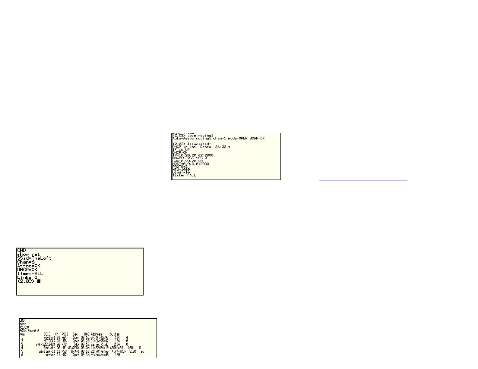
Type show net to displaythe current network settings.
Nowfinding all available networkswith the scan
command
If the networkyou re connecting to is open, youcan
simplyuse the join command to associate with the
accesspoint. From the scan listabove you can see
that roving1 isan open networkaccess point.
Type join roving1 to associate with an accesspoint.
You could alsohave specified the roving1 accesspoint
byusing the command join# 1
If the access point issecurityenabled you will need to
setthe passphrase priorto issuing the join command.
TheATC-2000 module will attempt toinquire and
determine the securityprotocol ofthe access point so
you do not have to set the authentication mode. To
setthe passphraseforWPAuse thecommand set
wlan phrase <string>.ForWEP set the keyusing the
set wlan key <num> command.
Onceyou have successfullyassociated to the network
the access point SSID isstored.Thisalongwith the
pass phrase can be savedto the config file so the
module can associatewith the networkeach timeit is
booted up.
8.7 Making connections
Tomakeaconnection into the module simplyopen a IP
socket and connect to the IPaddress of the module.
Telnetis asimple wayto test thisconnection. Fromin
Telnet type open <addr> <port>. In theexample above
the telnet command you looklike open 10.20.20.62
2000.Onceopen you can type charactersinto the
UARTwindowand see them on the Telnet window or
visa versa.
Tomakeaconnection fromthe module you will need IP
address and portnumber of youraserver application.
Asimple programto test this functionalityis a COMport
redirector.Thissoftwareopens an IP portand
transfers all data it receives to a specified COMport on
your machine. Afree com port redirectorprogram is
available from Pira at
http://www.pira.cz/eng/piracom.htm
After installingand starting this program, note the IP
address ofthe machine itis running on. This canbe
found byrunning ipconfig in the Microsoft command
window.With the ATC-2000WFmodule in command
mode type open <addr> <port>.The server will report
the connection isopen and you can type characters
into the UARTwindowandsee themon the server
window or visa versa.
8.8 Setting up Automatic Connections
Often, it isdesired on powerup (or wakeup) to
automaticallyconnect out to a remote server,send
data,and then disconnect.This can be configured to
happen automatically.
In the following example assume the network SSID and
securityhave been set correctlyand autojoin
isset to 1. This will also workin adhocmode(autojoin

4), howeverthere will be delayin connecting
to the adhocnetworkfrom the remote computerso set
the sleep timer large enough to allow the networkto get
set up and the autoconn establish a TCP connection.
When the module wakesup or ispowered on the
autoconn timer will cause the module to attempt a
connection to the storedremote IPaddressand port.
While thisconnectionis open the sleep timer
will not decrement. While data is flowing the idle timer
will not decrement. Once data stops for5seconds the
connection will beclosed. The sleeptimerwill the kick
in and put the module indeep
sleep.Finallythe wake timerwill startthe whole cycle
again one minute later.
setip host X.X.X.X ( set up theIP addressof the
remote machine )
setip remote_port num (set upthe IPportof the
remote machine )
setsys autoconn 1 (automaticallyconnect out after
READY)
setcom idle 5 (disconnectafter5 secondswith no
data activity)
setsys sleep 2 (sleep2 seconds after connection is
closed )
setsys wake 60 (wakeup after1 minute of sleeping )
save
8.9 Utilizing the Backup IP address/connect
function
ATC-2000WF containsa feature for auto-retryand
redundancy. If the first IP host addressconnection fails,
the backup IPwill be used (if set). If this fails(oris not
set) then the first DNSname will be
used. Ifthis fails (or isnot set) then the Backup DNS
name will be used.
To set the backup IPaddress, use:
set ip backup <address>
To set the backup DNS name, use:
set dns backup <string>
8.10 Firmware Upgrade over FTP
WiFlymodule has afile system for storing firmware,
web pagesand config files.Usethe ls command to
view files. File sizeisdisplayed in sectorsand the
active boot image is identified in the final message.
FL# SIZ FLAGS
1118 3WiFly_GSX-2.10
29 110 config
226 Free,Boot=11, Backup=11
Multiple firmware images and config filescan be stored
on the module file system.
FTPUpload and Upgrade
WiFlycontains a built in FTP client for getting files and
updating the firmware. The client uses
passive mode FTP, which allows operation thru
firewallsand the Internet.
To upload the latest released firmware from Roving
Networks the following setting are required:
FTPusername = roving
FTPpassword = Pass123
FTPfilename = wifly-GSX.img
FTPdirectory= ./public (thisparameter can not be
modified)
To use FTPto upgrade the firmware, enter the
following command:
ftp upload <string>(string isan optional filename, use
to bypass the default firmware filename)
The ftp upload command will retrieve the file and switch
the boot image to the new file.
<2.10> ftp update
<2.10> FTP connecting to 208.109.78.34
FTP file=30
.......................................................................
FTP OK.
The previousfirmware will become thebackup image.
Here isan example of what you should see
after a successful update:
FL# SIZ FLAGS
11 18 3 WiFly_GSX-2.05
29 1 10 config
30 18 3 WiFly_GSX-2.10
208 Free, Boot=30, Backup=11
Note the module mustbe rebooted or power cycled to
use thenew firmware. To boot adifferent
firmware use the following command:
Bootimage <num> setsthe current boot image <num>
For example to boot the previous image fromabove
use
<2.10> boot image 11
Set Boot Image 11, =OK
To upload yourown firmware orconfig file to the
module, change the stored FTPsettings: See
section 5.5 formore detailson the FTPcommands. To
upload yourfile w following command:
ftp get <string> Retrievesremote file with name

<string>
8.11 Restoring Defaultconfiguration settings:
Asof version 2.10 you can now specifya USER
configuration as the factory reset settings. Prior to
thisreleaseonlythe hardcoded factorydefaultswould
be restored.From command interface use the factory
RESET command to restore the defaults.From
hardware, setting PIO9 high on power up arms the
factoryreset functional and toggling PIO9
five (5)timesthere after causes the configuration
setting to restored to the factoryreset.
Nowhoweverif there is a config file named "user", it is
read in as the factorydefaults instead of using the
previous hardcoded defaults. Ifno "user" config file is
present, the hardcoded factorydefaultsareused.
The "user"config file iscreated using the "save user"
command which save the current configuration settings
into the “user”file.
Even if there is a “user”config file arming and toggling
PIO9 7 times will override the “user”settings
and restore the wiflymodule to the factoryhardcoded
defaults.Thisisa bypass mechanism in case
a bad configuration issaved into the “user”file.
Note: Factorydefaults should be saved to the configfile
using the save command and the module rebooted for
the new settings to take effect.
8.12 Supported Access Points
Access pointsthat are set to MIXEDmode (WPA1 and
WPA2) maycause problems during association
because some of these incorrectlyreport their security
mode.We also currentlydo not support
WPA2-Enterprise (radiusserver authentication,
EAP-TLS) The WiflyGSX should workwith any
standardAccess Point. Wehave tested the WiFly-GSX
module with the following access points
•Cisco Aeronet series
•Linksys (both standard and openWRT linux)
•NetgearWGR614 v8
•NetgearWGN54
•DLINK dir-615
•Airlink101
•AppleAirportexpress
•ADHOC MODE(Apple Iphone, Microsoft windows PC
with XP, Vista ,Ubuntu Linux)
Other ATC Media Converter manuals


Popular Media Converter manuals by other brands

Allen-Bradley
Allen-Bradley Rockwell Automation 842E-SIP Series user manual

almando
almando Multiplay Surround Decoder Installation and operating instructions

MiLAN
MiLAN MIL-140 installation guide

ADF Web
ADF Web AXIS HD67671-IP-2-A1 user manual

Reach
Reach ENC110 user manual

TerraTec
TerraTec Cameo Convert manual


