ATESS EVA-07D-SE User manual

single-phase AC charger Quick installation guide
1st Floor of Building 3 at Sector B and 3rd Floor of Building 9, Henglong
Industrial Park, Shuitian, Baoan District, Shenzhen
T +86 755 2998 8492
F +86 755 2998 5623
www.atesspower.com
Shenzhen ATESS Power Technology Co.,Ltd ATESS EVA-07D-SE/PE

This user manual is copyrighted by ATESS Power Technology Co.,ltd.
(hereinafter referred to as “ATESS”). No company or person may
extract or copy part or all of this user manual without the written
permission of ATESS Power Technology Co.,ltd. Content must not be
transmitted in any form, including materials and publications.
All rights reserved.
ATESS has the final right to interpret this user manual. The information
in this manual is subject to change without notice.
Disclaimer
EVA series intelligent three-phase AC charger is a power supply device
that uses professional and advanced technology to provide energy
supply to electric vehicles, it also has friendly man-machine interface
and versatile functions of control, billing, and communication. The
charger can be connected to a back-office server to realize the
functions of reservation and payment via Mobile phone APP. Diversified
communication options, including wired Ethernet, WIFI, 4G is available
for back-office server connection.
EVA-07D-SE has the function of not driving grounding pile, which
conforms to EN 61558-2-4 standard. Protection against electric shock is
provided by a device which disconnects the charging point from the live
conductors of the supply and from protective earth in accordance within
the 5S in the event of the voltage between the circuit protective
conductor and Earth exceeding 70 Vrms .The device will not operate if
the voltage exceeds 70 V rms for less than 4S.
We sincerely hope that this product can meet your needs and will
continuously improve the quality of our products.
Thank you for using ATESS EV charging equipment!
Menu
I. Product description ····························································
II. Packaging list ··································································
III. Installation and wiring ·······················································
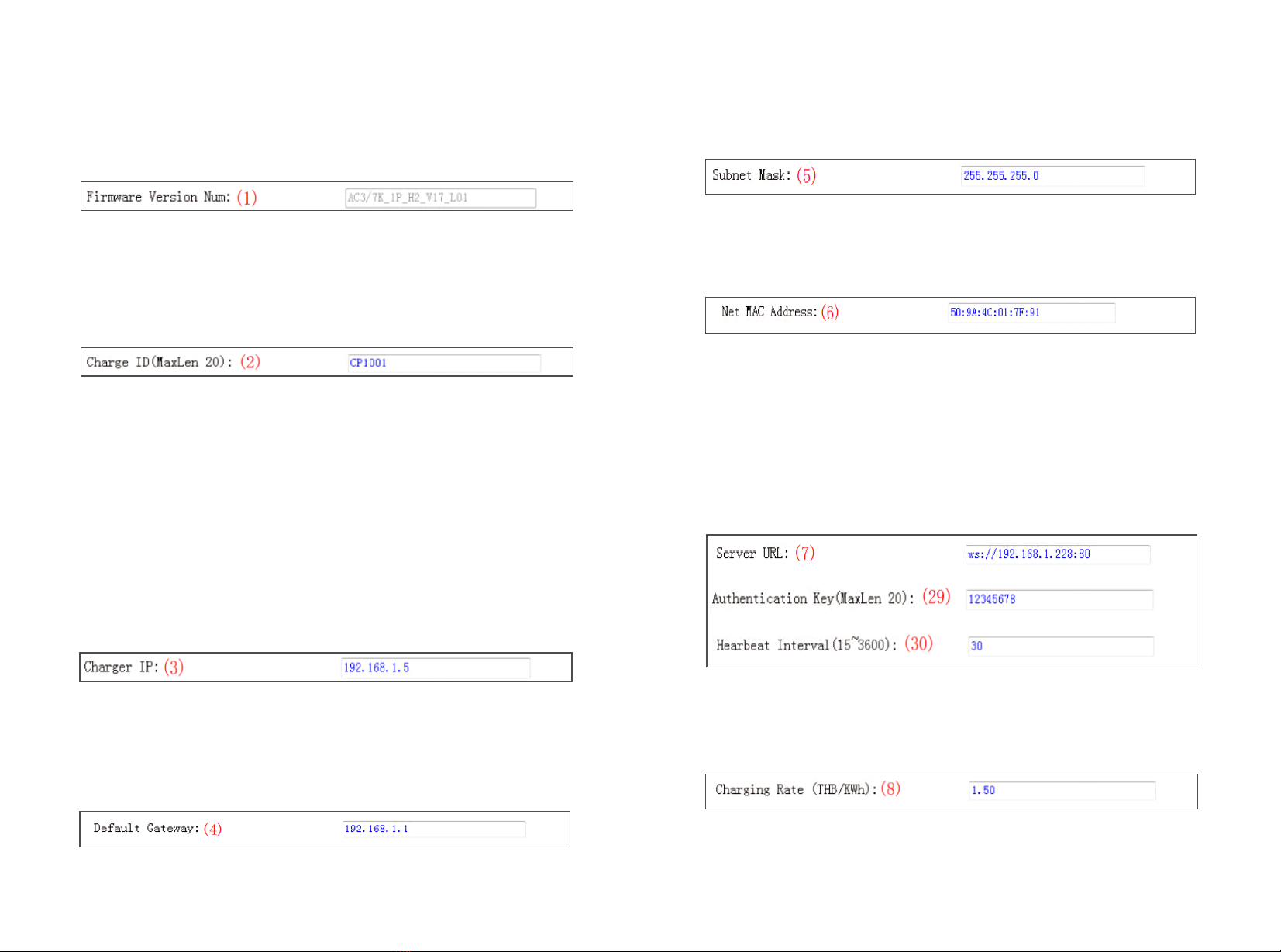
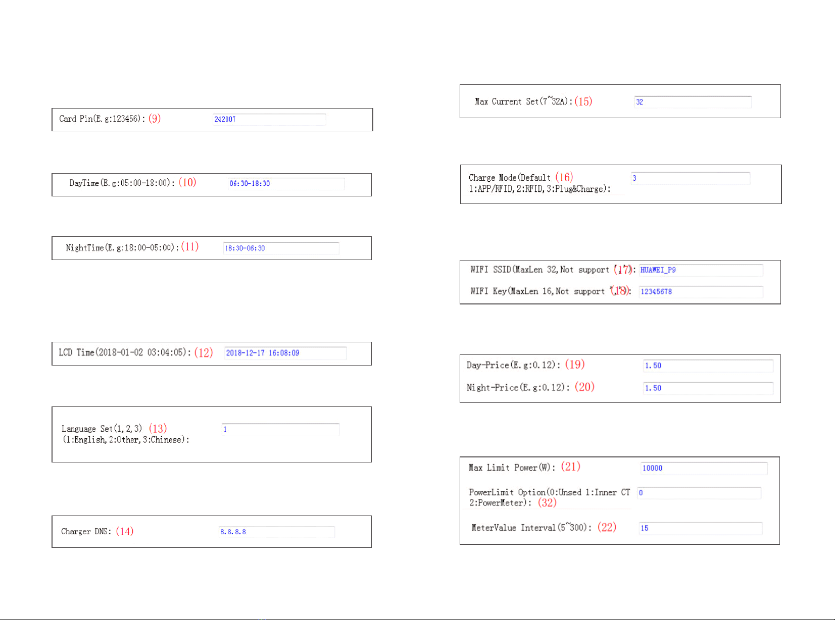
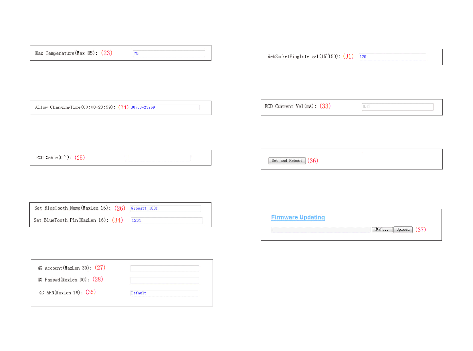
IV. Parameter setting ····························································
V. Operation instruction and LCD description ·····························
VI. Firmware update ······························································
VII. Troubleshooting ······························································
1
2
3
5
15
18
22
VIII. Intelligent power modulation ···········································
IX. Specification ·······················································
X. Annex1 ·······························································
XI. Annex2 ·······························································
32
33
46
30

I. Product description
12
1.LOGO and logo backlight
2.A/B status indictor
3.LCD display
4.Debug button/A/B gun switch
5.RFID reader
6.WIFI/4G Antenna
7.Emergency stop button
8.Socket outlet (plug holder for cabled version)
1
4
3
5
2
8
7
6
1
4
3
5
2
8
7
6
II. Packaging list
No. Name Qty Remark
1
2
3
4
1
1
1
Charger
User manual
Quality certificate
5
6
7
Cable hook
User card
M5*12 stainless
steels hex-head
self-drilling screws
2
3
4-10
For cabled version
PE cable
Chargepoint base
4 Fixed the bottom bracket
6 of 10 Pugs for cabled version,
cable hook fixing
8
9
M8*80 Plastic
expansion plugs For the bottom bracket
M4×8 Nickel
plating Pan head
cross
Pedestal
4
1
1

4
3
III. Installation and wiring
3.1.1 Open the packaging, you’ll see a charge point, a user manual, a pedestal and a bag
of mounting accessories. There is also an RFID card if the charge point is RFID version.
For cabled version, a cable hooker is also included inside.
3.1 Installation on the ground
3.1.2 The chargepoint must be installed on a hard surface, concrete surface is
recommended, it can also be mounted on a solid ground. Drill hols according to the
requirements marked on the illustration for fixing expansion bolts.
3.1.3 Fix the chargepoint onto the holes with expansion bolts. The input cables shall go
into the pole from the bottom middle area and come out of it from the area below the
cable hooker.
3.1.4 Crimp the below shown ring terminals on the end of the AC input wires and PE
wires. Connect the wires into the terminal block of the chargepoint as below.
Check the wiring and then close the switch and the door.
PE
N
L3
L2
L1
Model
11K
22K
11K
22K
≥6mm²
≥AWG9
≥16mm²
≥AWG5
L1 L2 L3 N PE
Terminal
Wire
≥6mm²
≥AWG9
≥16mm²
≥AWG5
≥6mm²
≥AWG9
≥16mm²
≥AWG5
≥6mm²
≥AWG9
≥16mm²
≥AWG5
≥6mm²
≥AWG9
≥16mm²
≥AWG5
3.2 According to different use scenarios of users, A PE wire is randomly attached to the
packaging accessories
1. For the earth free scenario, the metal shell of the charger does not need to be
connected to the PE column, and the PE line should be ignored.
2. For the scene requiring grounding, PE wire needs to be connected to PE row and PE
column.

56
After the installation and wiring is done, connect the Charger to a computer and configure
parameters via the web browser of the computer, then the Charger can be ready for use.
IV. Parameter setting
4.1 Set computer’s IP
The Charger’s default IP address is 192.168.1.5. To access the parameter setting
interface, you’ll need to first set the computer’s IP to 192.168.1.x(x can be any value
between 1 and 255 except for 5, e.g. 192.168.1.10).
To set a static IP on your Windows computer:
1. Click Start Menu > Control Panel > Network and Sharing Center. (For Windows 8 and
higher, search for and open Control Panel and select Network and Internet).
2. Click Change adapter settings.
3. Right-click on Local Area Connection and click on Properties.
4. Select Internet Protocol Version 4 (TCP/IPv4) and click on Properties.
The position of PE terminal

8
Connect the charger to a computer via a network cable. Open the web browser and type
in http://192.168.1.5:8080/ in the address field and click enter, then enter the password:
12345678 and click enter again,the parameter setting page of the charger will open up.
Parameter setting can only be done via web browser on a computer. It is suggested to
use IE or Firefox, other browser might have compatibility problem.
4.2 Configure parameters
5. Select "Use the following IP address" and enter the IP address, Subnet Mask,
Default Gateway. Click OK and close the Local Area Connection properties window.
Overview of Parameter setting page
7
Overview of Parameter setting page
enlarged view of parameter setting page_2
enlarged view of parameter setting page_1

9 10
(3) Charger IP. The default IP is 192.168.1.5. It is not suggested to change the default IP.
If you have changed the default IP and forgot the new IP, you can reset the charger to
factory setting by long press the reset button(the reset button on control board, not the red
emergency stop button) until the charger reboot. Then you can use the default
192.168.1.5 for access.
(1) Firmware version of the Charger. This item cannot be modified here on the setting
page.
Explanation of parameters:
Fig.1
(2) Charger ID, this is the unique identification of the Charger. If the charger is to be
connected to ATESS back-office server, this ID must be set as the serial number on the
nameplate of the Charger. Otherwise the Charger cannot be registered on the server.
Fig.2
Please note: After restoring the charger to factory setting, you’ll need to reset the charger
ID(same as serial number, can be found on the nameplate sticker) and server url,
otherwise the charger won’t be connected to the back-office server.
Fig.3
(4) Charger gateway. The default value is 192.168.1.1. It is not suggested to change. If
the gateway has been reset to other value and you have forgotten the new value, you can
restore the charger to factory setting by long press the reset button.
Fig.4
(5) Charger Subnet mask. The default value is 255.255.255.0. It is not suggested to
change. If the subnet mask has been reset to other value and you have forgotten the new
value, you can restore the charger to factory setting by long press the reset button.
Fig.5
(6) MAC address. This is the MAC address used for LAN cable connection. If the charger
is connected to ATESS back-office server via LAN cable and the router has MAC access
control, then you can put this MAC in the router to allow the charger to access server.
Fig.6
(7) Server URL is to set the domain name or IP address of the back office server to be
connected.
The domain name of ATESS server is “ws://ess-charge.atesspower.com:80/ocpp/ws”;
IP address is “ws://47.56.208.172:80/ocpp/ws”.
Authentication Key and Heartbeat Interval is used for testing and no need to reset.
Fig.7
(8) Charging fee per unit of electricity.
Fig.8

12
11
(9) PIN of the charger, used to verify the PIN of user card. To use a RFID card with the
charger, their PIN must be consistent. If the user card has a different PIN, then it cannot
be used on this charger. The default PIN setting of the charger is 242007.
Fig.9
(10) Peak time period. Set the time period of peak tariff.
Fig.10
(11) Off-peak time period. Set the time period of off-peak tariff.
Fig.11
(12) Time of the charger. Set according to the local time. After the charger is connected to
back-office server, the time will be synchronized with the server’s time. If the charger has
no server connection, then you’ll have to reset the time every time you turn off and back
on the charger.
Fig.12
(13)Language of LCD screen.
Fig.13
(14) Charger DNS setting, this only needs setting when the charger is to connect to
server via LAN cable.
Fig.14
(15) Set the max output of the charger.
(16) Charging mode setting. 1: APP/RFID mode; 2: RFID mode; 3: Plug&Charge mode.
Fig.15
Fig.16
(17) (18) WiFi SSID(wireless network name) and WiFi Key(WiFi password) is used for
WiFi connection.
Fig.17
(19) (20)Set peak tariff and off-peak tariff.
Fig.18
(21) (32) (22) Max power import to the property, Power sampling device selection, meter
value collection interval. These 3 parameters are used for power management setting.
Fig.19

14
13
(23) Over temperature protection value, not suggested to change.
(24) Charging-allowed time. Charging can only start within this time period. This is used
for off-peak charging setting.
If you want to charge out of this period, just press the forced on/off button at the side of
the charger.
Fig.20
Fig.21
(25) DC residual current sampling value calibration. Enter 0 and press “Set and Reboot”
to calibrate the DC RCD ring.
Fig.22
(26) (34) Bluetooth setting. Only needs setting when the charger is equipped with
Bluetooth.
Fig.23
(27) (28) (35) 4G connection setting.
Fig.24
(31) This is for communication testing, no need to reset.
Fig.25
(33) DC residual current real-time detection value.
Fig.26
(36) Press this button for the parameter change to take effect.
Fig.27
(37) This is used to upgrade firmware.
Fig.28

15 16
V. Operation instruction and LCD description
5.1 Charging mode and Operation
APP/RFID mode:
Initiate or cease charging by scanning QR code using APP or by swiping RFID card. You
can also use APP for reservation and payment provided that the back-office server
supports such functions.
APP/RFID mode operation process flow
If you are using the ATESS APP, Charging can be started/stopped by pressing the
ON/OFF button on the APP.
RFID mode:
Charging can only be initiated or ceased by swiping RFID card
RFID mode operation process flow
Plug & Charge:
When the charging gun is inserted into the electric vehicle,The charger will start to charge
auto matically . If you want to stop charging, you need to press the menu key and enter the
charging settings interface then you can select A or B.Reference part 5.2 interface
introduction.
Plug & Charge mode operation process flow

17
5.2 LCD interface introduction
Interface of stand by status.
Charging mode is displayed in the lower right
corner of the screen.
Interface of user card information
Displayed for user to check card ID and balance
when swiping RFID card while EV is not connected
Interface of charging status.
Displayed when the charging is being carried out.
There is charging time, consumed electricity,
charging cost on it, as well as real-time charging
voltage and charging current.
Interface of charging complete.
Displayed when the electric vehicle stops charging
or the charging pile stops charging.
Interface of debug
Hold down buttons A and B for 5s to enter
the debug interface and display the serial number
etc.
Iif the back-office server and APP support
reservation function and the charger is reserved,
this interface will come out showing user ID and
remaining time to
Interface of fault status.
Displayed with fault code and fault description
when fault occurs.
VI. Firmware update
There are 2 ways to update firmware for EV charger
1. Update by SD card
2. Update on parameter setting page
6.1 Update by SD card
1. Prepare a microSD card with capacity not greater than 4GB. Format the SD card using
FAT32.
The firmware file must be named as “App.bin”.
2. In the root directory of the SD card, rename the firmware file as “App.bin”. And create a
txt file with name of “UploadConfig.txt”.
18

19
20
3. Open the txt file, write “state=1” in it and save the file.
4. Turn off the charger and insert the SD card into the charger, the update will start
automatically. The indicator will first flash red and then flash green with a long beep as the
end of the update(sometimes the beep sound may not be clearly heard). After the update
is done, turn off the charger and remove the SD card.
Micro SD slot of dual output charger
5. Check the current FW version on LCD or the parameter setting page.
To check FW version on the paramete setting page
Connect the charger to computer via a network cable, the computer’s IP must be within
the 192.168.1.x segment(x is any value between 1 and 255 except 5).Open the web
browser, type in the charger’s default IP of “http://192.168.1.5:8080” and click enter, then
you can check the firmware version on the appeared parameter setting page.
6.2 Update on parameter setting page
Using this method for update doesn’t require any specific name for the firmware file.
1. Connect the charger to a computer with IP address set as 192.168.1.x(x can be any
value between 1 and 255 except 5) via a network cable. Open web browser and type in
the charger’s default IP address–http://192.168.1.5:8080, then enter the password
12345678 and click enter,you'll get into the parameter setting page.
2. Scroll down to the below field.

21 22
During the update, the LED indicator will behave as below,
First flash red and goes out with a short beep sound, during this period the firmware file is
transmitted to the charger’s flash memory from the computer;
Then flash red again for some seconds and quickly change to green light flashing. During
this period, the charger is updating the firmware to its micro controller.
When the greenlight goes out, there will be a long beep sound. That means the firmware
is successfully updated.
The beep sound may not be audible with the front cover fixed on the charger.
If the update doesn’t start after click “Upload”, Turn off and back on the charge to try
again.
4. You might see below content. If the charger is already successfully reboot after the
firmware update, close the browser and open it again to check the current firmware
version.
3. Click the “browse” button and select the firmware file. Click “Upload”, then update will
start automatically. VII. Troubleshooting
7.1 Troubleshoot by LED behavior or LCD display
If fault occurs, users can check the fault information on the LCD or by the number of
blinks of the LED indicator light. Each fault is indicated with a sequence of different
numbers of LCD blinking. A pause of 3 seconds between each sequence indicates the
beginning or end of a sequence. If multiple faults happen at the same time, each
sequence of blinking shows in chronological order at an interval of 3 seconds.
Please see the table below for detail information
No. Fault code on LCD (if available) Fault description
100
The emergency stop button is pressed
or broken
101
102
103
104
105
106
107
108
109
110
111
112
113
114
115
116
117
1000
Reserved
Reserved
Reserved
Reserved
Over voltage on phase L1
Under voltage on phase L1
Reserved
Over current
Over temperature
DC leakage current detected
RS485 communication fault
Reserved
Type A Switch Fault
Relay Fault
PE fault
PEN fault
Reserved
Other faults
2
3
4
1
5
6
7
8
9
10
11
12
13
14
15
16
17
18
19

23 24
7.2 Firmware update fails
7.2.1 Firmware update failure with SD card:
a. Check if the capacity is over 4G bytes,please use a SD card of less than 4GB to retry;
b. Check if the SD card is formatted with FAT32;
c. Check if the firmware file is renamed as App.bin;
d. Check if you have filled in “state=1” in the UploadConfig.txt file.
7.2.2 Firmware update failure with laptop:
Please try with IE browser. Or reboot the laptop to retry.
7.3 WiFi connection&APP issue
a. Check WiFi signal strength;
Signal strength on PC:
Signal strength on mobile:
b. Please check and input the correct WiFi SSID and password to retry;
If you check the WiFi setting on the APP,
please turn off and back on the charger and
connect your mobile to the WiFi emitted by
the charger for checking and setting.
c. Check if there is access control in the router, e.g. MAC filtering, port blocking, etc.
To verify this, you can use your mobile phone to create a hotspot and try to connect the
charger to this mobile hotspot. If charger can connect to the hotspot, but cannot connect
to the router, there must be access control in the router, please check with the site owner
for this.
Check if charger is connected on Device list of the hotspot setting page

25 26
1. Some routers have 2 WiFi, one is 2.4GHz, the other is 5GHz. Most homes just use the
5GHz WiFi as their default WiFi. But the charger can only connect to the 2.4GHz WiFi. So
if the charger can connect to your mobile phone hotspot, but cannot connect to the home
WiFi. Please check with the home owner or check on their router to see if you are using
the 5GHz WiFi. Please do use the 2.4GHz WiFi for charger connection.
2. When the WiFi signal strength is lower than - 75dbm, the charging point will not be able
to connect with WiFi.
(1) Download the WiFi signal strength test tool from the app store to check whether the
WiFi signal strength connected to the charging point is greater than - 75dbm.
(2) If the WiFi signal strength is weak, it is recommended to use AP repeater to increase
the signal strength, which can enlarge the WiFi signal range.
e. Check if the charger is still connected to the computer. Please unplug it from computer
otherwise the charger won’t connect to the back-office server.
f. Check if server address is correct in the“Server URL” field. The correct setting is :
ws://ess-charge.atesspower.com:80/ocpp/ws
7.4 Cannot accessparameter setting page
a. Check if you have connected the charger to your computer,
b. Check if you have change the computer’s IP to 192.168.1.x(x can be any value
between 1 and 255 except 5).
To set a static IP on your Windows computer:
(1). Click Start Menu>Control Panel>Network and Sharing Center. (For Windows 8 and
higher, search for and open Control Panel and select Network and Internet).
(2). Click Change adapter settings.

27 28
(3). Right-click on Local Area Connection and click on Properties.
(4). Select Internet Protocol Version 4 (TCP/IPv4) and click on Properties.
(5). Select "Use the following IP address" and enter the IP address, Subnet Mask, Default
Gateway. Click OK and close the Local Area Connection properties window.
c. Check what web browser is being used, it’s suggested to use Firefox or IE, Chrome
cannot be used to update firmware.
d. Check if you have input the complete content, which is http://192.168.1.5:8080, in the
address field, do not leave out the http:// or the“:8080”.
e. Sometimes you may need to restart the charger to access its parameter setting page.
f. If you have changed the charger’s IP to other value and cannot remember, you can
restore the charger to factory setting by long press the reset button. Then you can access
it using http://192.168.1.5:8080
Please note: After restoring the charger to factory setting, you’ll need to reset the charger
ID and server url, otherwise the charger won’t be connected to the back-office server.
Reset button

29 30
c. Check if off-peak charging is set and if charger’s time is correct.
If off-peak charging is set, charge can only start within the charging allowed time period.
7.5 Charging issue
If charging cannot start after the car is plugged in,
APP/RFID: Charge can only be started/stopped by APP or RFID card, and the charger
must be connected to the back office server already;
RFID: Charge can only be started/stopped by RFID card;
Plug&Charge: Charge will start automatically when car is plugged in.
a. Check if the red emergency stop button is pressed.
.
b. Check what charge mode is being used
VIII. Intelligent power modulation
Introduction
The charge point can monitor the total power consumption of the household during
charging. If the power consumption approaches the preset max value, the charge
point will reduce charge power to avoid the situation of main breaker trip due to
overload. It will adjust the charging power dynamically and in real-time thus the car
can always be charged with the maximum allowable power.
8.1 Meter is needed to detect the power import, please wire it as below:
Parameter configuration for this function
(1) Connect the charge point to a laptop with a network cable, access the
parameter setting page on the web browser of the laptop.
(2 ) S c r o l l dow n t o f i n d th e f o l l o wi n g p a r a me t e r : P ow e r D i s t ri b u t i on
Enable(0:Disable, 1:Enable) and set it to 1 to activate the power modulation
function.
(3) Select power sampling device in the field of the parameter: External Power
Sampling Wiring(0: Inner CT 1: PowerMeter). 0 means CT while 1 stands for meter.
Power Distribution
Charge(0:Disable,1:Enable)0
9 10

(4) Set the maximum power import value in the field of External Maxlimit
Power(kW). To avoid nuisance tripping of the main breaker, it is suggested to set
this parameter slightly lower than the max supply power of the property. e.g. the
max supply power is 15kW, you can set the max power import to 13kW or 14kW.
(5) Change PowerMeter Addr to the address shown on the meter, such as 002
shown in the figure below.
31 32
10
External Maxlimit Power(kW):
IX. Specification
Dimension(mm)
Weight(kg)
Display
Casing Material
Input
Voltage
Output
Voltage
Max current
IP Protection degree
Working environment temperature
Relative humidity
Altitude
Frequency
Communication
Standby power
Standard
Mounting
Certificate
Protection features
Overvoltage
Undervoltage
Overcurrent
Shortcircuit
Leakage protection
Over temperature
Lightning protection
420*270*1639(L*W*H)
22
LCD
Stainless steel& Engineering plastics& Tacrylic
AC 230V
AC 230V
32A*2
IP65
-25℃ ~ +50℃
5%~95%
≤2000m
50/60Hz
Ethernet/WIFI/4G
<8W
IEC-62196-2;EN61851
Ground
CE
260V
190V
40A
Yes
Type A+6mA DC RCD
Yes
Type II
Model EVA-07D-SE/PE
Charging mode
APP/RFID/Plug and Charge

X. Annex1
10.1. APP Introduction
10.1.1 Description
ATS Charge is an app for controlling charger. It can help you quickly and easily charge
your vehicle with a charger.
10.1.2 Main Function Of ATS Charge
(1) The user can add a charger by entering the chargepoint serial number and scanning
the QR code.
(2) The user can control the start and stop of the charger through the APP.
(3) The user can preset the charging scheme and reserve charging.
(4) The user can modify the parameter settings of the charger.
(5) Users can authorize other users to use their own charger.
(6) The user can view the charging record.
(7) Users can manage and set up their own accounts.
10.1.3 Performance
APP has good ease of use and reliability, and guarantees the security and confidentiality
of information.
10.2. Instructions
10.2.1 APP download and install
Android phone users can search and install “ATS Charge" through Google paly.
iPhone users can search and install “ATS Charge" through the App Store.
10.2.2 Registration and login
When the user has an account, you can directly enter the user name and password to log
in. If you forget the password, you can click the login page, forget the password button,
and follow the prompts to retrieve the password through the mailbox.
IF you use ATS Charge for the first time, you need to add charger in the APP to facilitate
setting and controlling the charger.
The process of adding a charger is as follows:
Click “Add” to add a charger by scanning the code or entering the charger ID.
When the user first visits, the user registration is performed by the following steps: Click
the desktop icon Login page Register.
10.2.3 Add
33 34

10.2.4 Charger switching and removal
When there are multiple chargepoint, you can switch the chargepoint by clicking on the
name of the chargepoint above. Press and hold the chargepoint name to remove the
chargepoint. You can add a new chargepoint by adding a button.
10.2.5 Start and stop control of charger
Press to turn on/off.
Note: when charger status is Preparing , you can press to start charging.
When the chargepoint status is preparing, the user can use the preset charging scheme
and the reserved charging function.
When charging, the preset charging scheme, the amount of charge, the amount of
consumption, the duration of charging, the charging rate, the current current, and the
current voltage are displayed.
10.2.6 Preset charging scheme and reservation function
Preset charging scheme:
You can make an appointment to charge according to the amount, amount of electricity,
and duration. For example, if the preset power is 20kwh, the chargepoint will automatically
stop charging when the charging power reaches 20kwh.
Only one of the three charging schemes can be selected to take effect.
①Click the cost to set the preset amount. When the preset amount is reached, the
charger stops charging.
②Click the energy to set the preset power. When the preset power is reached, the
charger stops charging.
③Click the time to set the preset time. When the preset duration is reached, the charger
stops charging.
35 36
This manual suits for next models
1
Table of contents
Other ATESS Batteries Charger manuals