ATESS EVA-11D User manual

3-phase dual output AC charging equipment
ATESS EVA-11/22D
Shenzhen Growatt Power Technology Co.,Ltd
1st Floor of Building 3 at Sector B and 3rd Floor of Building 9, Henglong
Industrial Park, Shuitian, Baoan District, Shenzhen
T+86 755 2998 8492
F+86 755 2998 5623
Wwww.atesspower.com

This user manual is copyrighted by Growatt Power Technology. (hereinafter
referred to as “Growatt Power Technology”). No company or person may
extract or copy part or all of this user manual without the written
permission of Growatt Power Technology. Content must not be
transmitted in any form, including materials and publications.
All rights reserved.
Growatt Power Technology has the final right to interpret this user
manual. The information in this manual is subject to change without
notice.
Disclaimer
EVA series intelligent single-phase AC charger is a power supply device
that uses professional and advanced technology to provide energy supply
to electric vehicles, it also has friendly man-machine interface and versatile
functions of control, billing, and communication. The charger can be
connected to a back-office server to realize the functions of reservation
and payment via Mobile phone APP. Diversified communication options,
including wired Ethernet, WIFI, 4G is available for back-office server
connection.
We sincerely hope that this product can meet your needs and will
continuously improve the quality of our products.
Thank you for using ATESS EV charging equipment!
Menu
I. Product description ·········································································
II. Packaging list ·················································································
III. Installation and wiring ···································································
IV. Parameter setting ···········································································
V. Operation instruction and LCD description ······································
VI. Firmware update ···········································································
VII. Troubleshooting ···········································································
1
2
3
5
15
19
23
VIII. Specification ···············································································
IX. Annex ···························································································
31
32

I. Product description
12
1.LOGO and logo backlight
2.Status indictor
3.LCD display
4.WIFI/4G Antenna
5.Emergency stop button
6.Settings button
7. RFID reader
8.Socket outlet (plug holder for cabled version)
II. Packaging list
No. Name Qty Remark
1
2
3
4
1
1
1
1
Charger
User manual
Quality certificate
Mounting bracket
5
6
7
Cable hook
ST6.3X40
Stainless steel hex-head
self-drilling screws
12X46
Plastic expansion plugs
1
4-7
4-7
For cabled version
4 for socket version, 7 for cabled
version(3 of the 7 screws is for
cable hook fixing)
4 for socket version, 7 for cabled
version(3 of the 7 plugs is for
cable hook fixing)
8User card 4
4
5
8
1
2
3
6
7

4
3
III. Installation and wiring
3.1.1 Open the packaging, you’ll see a charge point, a mounting bracket, a user manual and
a bag of mounting accessories. There is also an RFID card if the charge point is RFID version.
For cabled version, a cable hooker is also included inside.
3.1 Installation on the ground
3.1.2 The chargepoint must be installed on a hard surface, concrete surface is recommended,
it can also be mounted on a solid ground. Drill hols according to the requirements marked on
the illustration for fixing expansion bolts.
3.1.3 Fix the chargepoint onto the holes with expansion bolts. The input cables shall go into
the pole from the bottom middle area and come out of it from the area below the cable
hooker.
3.1.4 Crimp the below shown ring terminals on the end of the AC input wires and PE wires.
Connect the wires into the terminal block of the chargepoint as below.
Check the wiring and then close the switch and the door.

56
After the installation and wiring is done, connect the Charger to a computer and configure
parameters via the web browser of the computer, then the Charger can be ready for use.
IV. Parameter setting
4.1 Set computer’s IP
The Charger’s default IP address is 192.168.1.5. To access the parameter setting interface,
you’ll need to first set the computer’s IP to 192.168.1.x(x can be any value between 1 and
255 except for 5, e.g. 192.168.1.10).
To set a static IP on your Windows computer:
1. Click Start Menu > Control Panel > Network and Sharing Center. (For Windows 8 and
higher, search for and open Control Panel and select Network and Internet).
2. Click Change adapter settings.
3. Right-click on Local Area Connection and click on Properties.
4. Select Internet Protocol Version 4 (TCP/IPv4) and click on Properties.

8
Connect the charger to a computer via a network cable. Open the web browser and type in
http://192.168.1.5:8080/ in the address field and click enter, then the parameter setting page
of the charger will open up.
Parameter setting can only be done via web browser on a computer. It is suggested to use IE
or Firefox, other browser might have compatibility problem.
4.2 Configure parameters
5. Select "Use the following IP address" and enter the IP address, Subnet Mask,
Default Gateway. Click OK and close the Local Area Connection properties window.
Overview of Parameter setting page
7
Overview of Parameter setting page
enlarged view of parameter setting page_2
enlarged view of parameter setting page_1

9 10
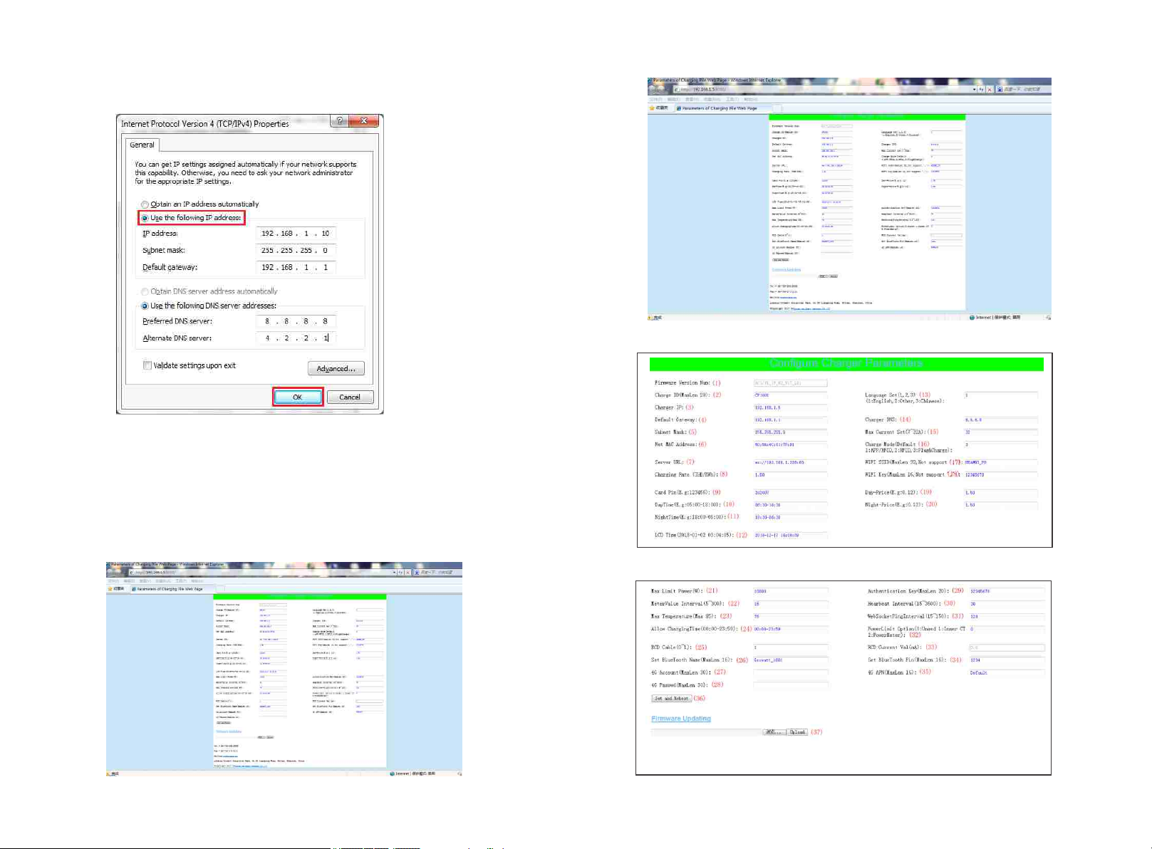
(3) Charger IP. The default IP is 192.168.1.5. It is not suggested to change the default IP. If
you have changed the default IP and forgot the new IP, you can reset the charger to factory
setting by long press the reset button(the reset button on control board, not the red
emergency stop button) until the charger reboot. Then you can use the default 192.168.1.5
for access.
(1) Firmware version of the Charger. This item cannot be modified here on the setting page.
Explanation of parameters:
Fig.1
(2) Charger ID, this is the unique identification of the Charger. If the charger is to be
connected to Growatt back-office server, this ID must be set as the serial number on the
nameplate of the Charger. Otherwise the Charger cannot be registered on the server.
Fig.2
Please note: After restoring the charger to factory setting, you’ll need to reset the charger
ID(same as serial number, can be found on the nameplate sticker) and server url, otherwise
the charger won’t be connected to the back-office server.
Fig.3
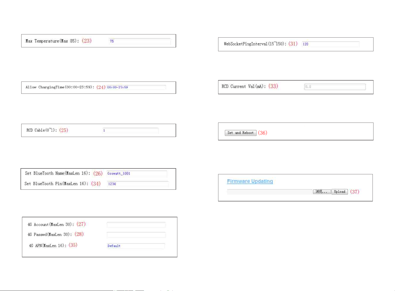
(4) Charger gateway. The default value is 192.168.1.1. It is not suggested to change. If the
gateway has been reset to other value and you have forgotten the new value, you can
restore the charger to factory setting by long press the reset button.
Fig.4
(5) Charger Subnet mask. The default value is 255.255.255.0. It is not suggested to change.
If the subnet mask has been reset to other value and you have forgotten the new value, you
can restore the charger to factory setting by long press the reset button.
Fig.5
(6) MAC address. This is the MAC address used for LAN cable connection. If the charger is
connected to Growatt back-office server via LAN cable and the router has MAC access
control, then you can put this MAC in the router to allow the charger to access server
Fig.6
(7) Server URL is to set the domain name or IP address of the back office server to be
connected.
The domain name of Growatt server is “ws://charge.growatt.com:80/ocpp/ws”;
IP address is “ws://47.254.157.66:80/ocpp/ws”.
Authentication Key and Heartbeat Interval is used for testing and no need to reset.
Fig.7
(8) Charging fee per unit of electricity.
Fig.8

12
11
(9) PIN of the charger, used to verify the PIN of user card. To use a RFID card with the charger,
their PIN must be consistent. If the user card has a different PIN, then it cannot be used on
this charger. The default PIN setting of the charger is 242007.
Fig.9
(10) Peak time period. Set the time period of peak tariff.
Fig.10
(11) Off-peak time period. Set the time period of off-peak tariff.
Fig.11
(12) Time of the charger. Set according to the local time. After the charger is connected to
back-office server, the time will be synchronized with the server’s time. If the charger has no
server connection, then you’ll have to reset the time every time you turn off and back on the
charger.
Fig.12
(13)Language of LCD screen.
Fig.13
(14) Charger DNS setting, this only needs setting when the charger is to connect to server
via LAN cable.
Fig.14
(15) Set the max output of the charger.
(16) Charging mode setting. 1: APP/RFID mode; 2: RFID mode; 3: Plug&Charge mode.
Fig.15
Fig.16
(17)(18) WiFi SSID(wireless network name) and WiFi Key(WiFi password) is used for WiFi
connection.
Fig.17
(19) (20)Set peak tariff and off-peak tariff.
Fig.18
(21)(32)(22) Max power import to the property, Power sampling device selection, meter
value collection interval. These 3 parameters are used for power management setting.
Fig.19

14
13
(23) Over temperature protection value, not suggested to change.
(24) Charging-allowed time. Charging can only start within this time period. This is used for
off-peak charging setting.
If you want to charge out of this period, just press the forced on/off button at the side of the
charger.
Fig.20
Fig.21
(25) DC residual current sampling value calibration. Enter 0 and press “Set and Reboot” to
calibrate the DC RCD ring.
Fig.22
(26) (34) Bluetooth setting. Only needs setting when the charger is equipped with Bluetooth.
Fig.23
(27)(28) (35) 4G connection setting.
Fig.24
(31) This is for communication testing, no need to reset.
Fig.25
(33) DC residual current real-time detection value.
Fig.26
(36) Press this button for the parameter change to take effect.
Fig.27
(37) This is used to upgrade firmware.
Fig.28

15 16
V. Operation instruction and LCD description
5.1 Charging mode and Operation
APP/RFID mode:
Initiate or cease charging by scanning QR code using APP or by swiping RFID card. You can
also use APP for reservation and payment provided that the back-office server supports such
functions.
APP/RFID mode operation process flow
If you are using the ProjectEV APP, Charging can be started/stopped by pressing the ON/OFF
button on the APP.
RFID mode:
Charging can only be initiated or ceased by swiping RFID card
RFID mode operation process flow
Plug & Charge:
When the charging gun is inserted into the electric vehicle,The charger will start to charge
auto matically . If you want to stop charging, you need to press the menu key and enter the
charging settings interface then you can select A or B.Reference part 5.2 interface
introduction.
Plug & Charge mode operation process flow

17 18
5.2 LCD interface introduction
Interface of standby status.
Charging mode is displayed at the bottom centre of
the screen.
Interface of user card information
Displayed for user to check card ID and balance when
swiping RFID card while EV is not connected
Interface of charging status.
Displayed when the charging is being carried out.
There is charging time, consumed electricity,
charging cost on it, as well as real-time charging
voltage and charging current.
Interface of charging complete.
Displayed when the EV stops charging, or forced
on/off button is pressed on charger side.
Interface of billing.
After scanning QR code or swiping RFID card for
billing, this interface will open up to display user
ID/charging time/cost/balance, etc.This interface will
also come out when you stop charging on the Project
EV APP or when you press the forced on/off button
or unplug the gun at Plug&Charge mode.
Interface of fault status.
Displayed with fault code and fault description when
fault occurs.
Interface of reserved status.
If the back-office server and APP support reservation
function and the charger is reserved, this interface
will come out showing user ID and remaining time to
reserved time.
Press the menu button to enter the charge
station setting interface
Interface of charge setting
In the charging setting interface,you can choose
A or B to start and stop
Interface of unlock setting.
In the electromagnetic lock failure state, you can
choose to unlock A or B
Interface of language setting.
You can choose English or Chinese
Interface of Charge mode setting.
You can set different charging control modes
( APP/RFID、RFID、Plug&Charge)

19
20
VI. Firmware update
There are 2 ways to update firmware for EV charger
1. Update by SD card
2. Update on parameter setting page
6.1 Update by SD card
1. Prepare a microSD card with capacity not greater than 4G. Format the SD card using
FAT32.
The firmware file must be named as “App.bin”.
2. In the root directory of the SD card, rename the firmware file as “App.bin”. And create a
txt file with name of “UploadConfig.txt”.
3. Open the txt file, write “state=1” in it and save the file.
4. Insert the SD card into the charger, turn off and back on the charger, the update will start
automatically. The indicator will first flash red and then flash green with a long beep as the
end of the update(sometimes the beep sound may not be clearly heard). After the update is
done, turn off the charger and remove the SD card.
Micro SD slot of dual output charger
5. Check the current FW version on LCD or the parameter setting page.
To check FW version on the paramete setting page
Connect the charger to computer via a network cable, the computer’s IP must be within the
192.168.1.x segment(x is any value between 1 and 255 except 5).Open the web browser,
type in the charger’s default IP of “http://192.168.1.5:8080” and click enter, then you can
check the firmware version on the appeared parameter setting page.

21 22
6.2 Update on parameter setting page
Using this method for update doesn’t require any specific name for the firmware file.
1. Connect the charger to a computer with IP address set as 192.168.1.x(x can be any value
between 1 and 255 except 5) via a network cable. Open web browser and type in the
charger’s default IP address–http://192.168.1.5:8080, click enter then you’ll get into the
parameter setting page.
2. Scroll down to the below field.
During the update, the LED indicator will behave as below,
First flash red and goes out with a short beep sound, during this period the firmware file is
transmitted to the charger’s flash memory from the computer;
Then flash red again for some seconds and quickly change to green light flashing. During this
period, the charger is updating the firmware to its micro controller.
When the greenlight goes out, there will be a long beep sound. That means the firmware is
successfully updated.
The beep sound may not be audible with the front cover fixed on the charger.
If the update doesn’t start after click “Upload”, Turn off and back on the charge to try again.
4. You might see below content. If the charger is already successfully reboot after the
firmware update, close the browser and open it again to check the current firmware version.
3. Click the “Browse” button and select the firmware file. Click “Upload”, then update will
start automatically.

VII. Troubleshooting
7.1 Troubleshoot by LED behavior or LCD display
If fault occurs, users can check the fault information on the LCD or by the number of blinks
of the LED indicator light. Each fault is indicated with a sequence of different numbers of
LCD blinking. A pause of 3 seconds between each sequence indicates the beginning or end
of a sequence. If multiple faults happen at the same time, each sequence of blinking shows
in chronological order at an interval of 3 seconds.
Please see the table below for detail information
No. Fault code on LCD (if available) Fault description
1
100
The red emergency stop button is pressed
or broken
2
3
4
5
6
7
8
9
10
11
12
13
14
15
16
17
18
19
101
102
103
104
105
106
107
108
109
110
111
112
113
114
115
116
117
1000
Over voltage on phase L3
Under voltage on phase L3
Over voltage on phase L2
Under voltage on phase L2
Over voltage on phase L1
Under voltage on phase L1
Under voltage on all 3 phases
Over current
Over temperature
DC leakage current detected
RS485 communication fault
Lightning protection fault
Type A switch fault
Relay adhesion fault
Reserved
Reserved
Reserved
Other faults
23 24
7.2 Firmware update fails
7.2.1 Firmware update failure with SD card:
a. Check if the capacity is over 4G bytes,please use a SD card of less than 4G to retry;
b. Check if the SD card is formatted with FAT32;
c. Check if the firmware file is renamed as App.bin;
d. Check if you have filled in “state=1” in the UploadConfig.txt file.
7.2.2 Firmware update failure with laptop:
Please try with IE browser. Or reboot the laptop to retry.
7.3 WiFi connection&APP issue
a. Check WiFi signal strength;
Signal strength on PC:
Signal strength on mobile:

25 26
b. Please check and input the correct WiFi SSID and password to retry;
If you check the WiFi setting on the APP, please
turn off and back on the charger and connect
your mobile to the WiFi emitted by the charger
for checking and setting.
c. Check if there is access control in the router, e.g. MAC filtering, port blocking, etc.
To verify this, you can use your mobile phone to create a hotspot and try to connect the
charger to this mobile hotspot. If charger can connect to the hotspot, but cannot connect to
the router, there must be access control in the router, please check with the site owner for
this.
Check if charger is connected on Device list of the hotspot setting page
d. Some routers have 2 WiFi, one is 2.4GHz, the other is 5GHz. Most homes just use the
5GHz WiFi as their default WiFi. But the charger can only connect to the 2.4GHz WiFi. So if
the charger can connect to your mobile phone hotspot, but cannot connect to the home
WiFi. Please check with the home owner or check on their router to see if you are using the
5GHz WiFi. Please do use the 2.4GHz WiFi for charger connection.

e. Check if the charger is still connected to the computer. Please unplug it from computer
otherwise the charger won’t connect to the back-office server.
f. Check if server address is correct in the“Server URL” field. The correct setting is :
ws://charge.growatt.com:80/ocpp/ws
7.4 Cannot accessparameter setting page
a. Check if you have connected the charger to your computer,
b. Check if you have change the computer’s IP to 192.168.1.x(x can be any value between 1
and 255 except 5).
To set a static IP on your Windows computer:
(1). Click Start Menu>Control Panel>Network and Sharing Center. (For Windows 8 and
higher, search for and open Control Panel and select Network and Internet).
(2). Click Change adapter settings.
27 28
(3). Right-click on Local Area Connection and click on Properties.
(4). Select Internet Protocol Version 4 (TCP/IPv4) and click on Properties.
(5). Select "Use the following IP address" and enter the IP address, Subnet Mask, Default
Gateway. Click OK and close the Local Area Connection properties window.

Reset button
c. Check what web browser is being used, it’s suggested to use Firefox or IE, Chrome cannot
be used to update firmware.
d. Check if you have input the complete content, which is http://192.168.1.5:8080, in the
address field, do not leave out the http:// or the“:8080”.
e. Sometimes you may need to restart the charger to access its parameter setting page.
f. If you have changed the charger’s IP to other value and cannot remember, you can restore
the charger to factory setting by long press the reset button. Then you can access it using
http://192.168.1.5:8080
Please note: After restoring the charger to factory setting, you’ll need to reset the charger ID
and server url, otherwise the charger won’t be connected to the back-office server.
29 30
c. Check if off-peak charging is set and if charger’s time is correct.
If off-peak charging is set, charge can only start within the charging allowed time period.
7.5 Charging issue
If charging cannot start after the car is plugged in,
APP/RFID: Charge can only be started/stopped by APP or RFID card, and the charger must be
connected to the back office server already;
RFID: Charge can only be started/stopped by RFID card;
Plug&Charge: Charge will start automatically when car is plugged in.
a. Check if the red emergency stop button is pressed.
.
b. Check what charge mode is being used

31 32
VIII. Specification IX. Annex
9.1 Electrical diagram
Fig 9-1. Main circuit diagram
Dimension(mm)
Weight(kg)
Display
Casing Material
Input
Voltage
Max current
Output
Voltage
Max current
IP Protection degree
Working environment temperature
Relative humidity
Altitude
Frequency
Communication
Payment
Standby power
Standard
Mounting
Certificate
Protection features
Overvoltage
Undervoltage
Overcurrent
Shortcircuit
Leakage protection
Over temperature
Lightning protection
386*260*1635(L*W*H)
30
LCD
Stainless steel& Engineering plastics& Tempered glass
AC 400V
16A/32A
AC 400V
16A/32A
IP65
-20℃〜+65℃
5%〜95%
≤2000m
50 Hz ±1Hz
Ethernet/WIFI/4G/485
RFID/APP
<8W
IEC-62196-2;EN61851
Ground
CE
457V
304V
20A/40A
Yes
No/Type A/Type A+6mA DC RCD
Yes
Type II
Model EVA-11/22D
9.2 Contact
Shenzhen Growatt Power Technology Co.,Ltd
Address:1st Floor of Building 3 at Sector B and 3rd Floor of Building 9, Henglong,
Industrial Park, Shuitian, Baoan District, Shenzhen, 518000, China
Website:www.atesspower.com
Service hotline:+8675529988492
E-mail:service@atesspower.com
This manual suits for next models
1
Table of contents
Other ATESS Batteries Charger manuals
Popular Batteries Charger manuals by other brands

Pro Charging Systems
Pro Charging Systems i36154815 Safety, installation and operating instructions

QuickCable
QuickCable Q600 manual

Xantrex
Xantrex Truecharge2 804-1220-02 owner's guide

F.F. Group
F.F. Group 41 323 Original instructions

MOB
MOB MO6253 user manual

Chargetek
Chargetek RTIC-2210-WP installation manual