10
9
No. Parameters Function description
1
2
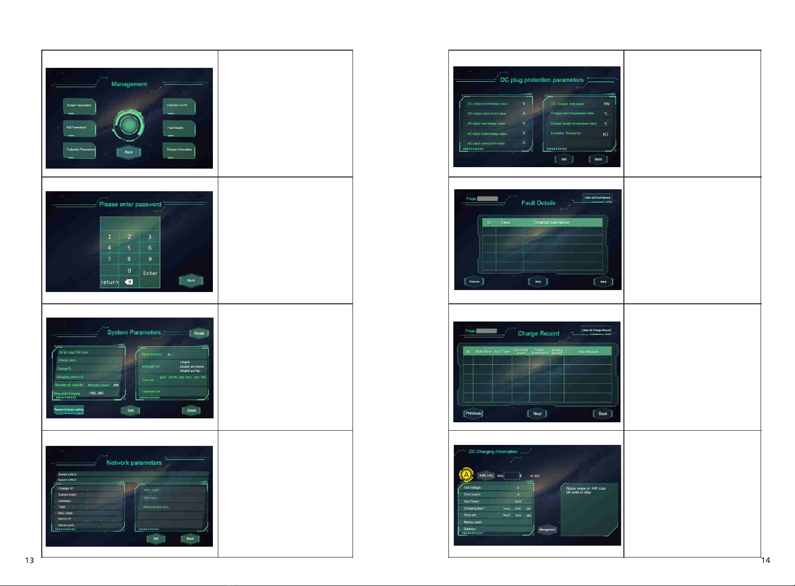
3Charger IP
Server URL2
Server URL1 Server address setting, used to set domain or IP
address of back-office server.
IP setting of the charging equipment
Address of backup server. This parameter is not
available now, reserved for future use.
4Subnet mask Subnet mask setting
5Gateway Gateway setting
6DNS DNS server address
7MAC Addr MAC address
8Server IP Server IP address
9Server port Server port number
10 WIFI SSID
WIFI SSID setting, to set the name of the wireless
network to which the charging equipment is to
be connected. A reserved function for future use
11 WIFI Key WiFi password setting. A reserved function for
future use
12 Authentication Key OCPP login authentication setting
4.3 Protection parameters
The protection-related parameters, such as voltage, current, temperature, power,
etc.
No. Parameters Function description
1
2
3
4
5
6
7
8
9
DC output overvoltage value
DC output overcurrent value
AC input overvoltage value
AC input undervoltage value
AC input overcurrent value
DC output limit power
Charger over temperature value
Charger derate temperature value
Insulation Resistance
Over voltage limit setting of DC
output
Over current limit setting of DC
output
Over voltage limit setting of AC
input
Under voltage limit setting of AC
input
Over current limit setting of AC
input
Power limitation setting of DC
output
Over temperature limit setting of
charging connector
Charging connector’s temperature
at which the charging equipment
starts decreasing output power
The min value of insulation resistance