ATESS HPS50 User manual

HPS50
Hybrid energy system User Manual
044.ZT00007-00
Shenzhen Growatt Power Technology Co.,Ltd
1st Floor of Building 3 at Sector B and 3rd Floor of Building 9,
Henglong Industrial Park, No.4 Industrial Zone, Shuitian
Community, Shiyan Street, Baoan District, Shenzhen
W: www.atessp.com
F: +86 755 2998 5623
T: +86 755 2998 8492
E: info@atesspower.com

About this Manual
Safety instructions
Product Description
Contents
1
2
3
1.1 Contents
1.2 Target readers
1.3 How to use this Manual
1.4 Symbols explanation
2.1 Installation
2.2 Operator
2.3 Inspection and storage
2.4 Transportation
2.5 Repair and maintenance
2.6 Inverter EMC and noise level
2.7 Important note
3.1 Energy Storage system
3.2 Circuit diagram of the inverter
3.3 The layout of the main components
3.4 Operation mode
3.5 Battery setting
3.6 Protection
3.7 Storage
3.8 Dimension
3.9 Packaging information
GUI instruction
6
Pilot operation
5.2 Inspection
5.4 Pilot operation completion
5.3 Power on steps
5.1 Relevant requirements
5
5.5 Power off steps
6.1 LCD display screen introduction
6.2 LCD operation
6.3 LCD display information schedule
Routine maintenance
77.1 Regular maintenance
7.2 Waste disposal
Products installation
4
4.2 Tools and spare parts required for
whole machine installation
4.4 Electrical installation
4.3 Mechanical installation
4.1 Installation condition requirements
4.5 Communication
4.6 Installation inspection
Appendix
8
8.1 Specification
8.2 ATESS Factory warranty
8.3 Contact

1 About this Manual
This chapter describes the contents of this manual, target reader, and safety
symbols, can help users to have a better understanding of the manual.
1.1. Contents
This manual applies to ATESS HPS50 hybrid energysystem, the manual
contains:
safety instruction
Product description
The role inverter plays in the energy storage system and structure, principle,
protection, operation mode, storage and package size of the ATESS HPS50.
Installation
Inverter installation conditions, tools, and the inverter mechanical and electrical
installation, the communication connection and inspection.
Commissioning
GUI(Graphic User Interface) instruction
Routine maintenance
Daily maintenance of the inverter, the replacement of some spare parts and waste
disposal instruction.
Appendix
2
Attention that needs to be paid when operating and maintaining ATESS HPS50.
Inspection before commissioning and procedure to turn on/off inverter.
Information displayed on the inverter LCD touch-screen and setting instruction.
Technical data, warranty policy and contact information.
1.2. Target readers
1) Only professional electricians or professionally qualified personnel can
transport or install this product.
2)The operator should be fully familiar with the structure and working principle
of the entire Energy Storage system;
3)The operator should be fully familiar with this manual;
4)The operator should be fully familiar with the local standards of the project.
Qualification
1.3. How to use this Manual
Read this manual before installation of the ATESS HPS50. Store this manual
where accessible at all times.
The contents of this manual will be periodically updated or revised if necessary.
However discrepancies cannot be excluded. Please refer to the product or
download the latest version of this manual on www.atessp.com.
1.4. Symbols explanation
In order to ensure the personal and property safety of the user during installation,
or optimally efficient use of this product, symbols are used highlight the
information. The following symbols may be used in this manual, please read
carefully, in order to make better use of this manual.
DANGER
Caution, risk of danger
DANGER indicates a hazard with a high level of risk which, if not avoided, will
result in death or serious injury.
CAUTION
CAUTION indicates there is potential risk, if not avoided,
could result in equipment malfunction and property damage.
1

4
WARNING
Caution,risk of electric shock
WARNING
Caution, risk of fire hazard
PE TERMINAL
Protective conductor terminal
WARNING
Risk of electric shock, Energy storage timed discharge.
3
When battery bank connecting point are exposed, there will be DC voltage in
the equipment DC side; and when output breaker is on, there is a potential
risk of electric shock.
Suitable for mounting on concrete or other non-combustible
surface only.
The inverter has to be firmly grounded to ensure the safety of
personnel.
Electrical shock danger exists in the capacitor; the cover shall
be moved at least 5 minutes later after all powers are
Safety instructions 2
Inverter installation and service personnel must be trained and familiar with the
general safety requirement when working on electrical equipment. Installation and
service personnel should also be familiar with the local laws and regulations and
safety requirements.
> Read this manual carefully before operation. The equipment will not be under
warranty if failing to operate according to this manual.
> Operation on the inverter must be for qualified electrical technician only.
> When inverter operating, don’t touch any electrical parts except for the touch-
screen.
> All electrical operation must comply with local electrical operation standards.
> Warranty service for the inverter does not contain module maintenance.
> Permission from the local utility company is required before installing the Energy
Storage system and only professional personnel are qualified for the operation.
2.1. Installation
Proper installation requires following all the instructions in the user manual
involving transportation, mounting, wiring and commissioning. ATESS does not
cover warranty for the inverter damage due to failing to use it properly.
The protection level of the inverter is IP20, which is designed for indoor
installation. Please refer to chapter 4 for installation instruction.
The installation location must be dry, including no expected condensation. The
inverter is only for use in a closed electrical operating area.
Caution, risk of fire hazard
WARNING Suitable for mounting on concrete or other non-combustible
surface only.

56
CAUTION
ATESS HPS50 can only be stored when it is stopped and all
the doors are closed in a dry room to protect the internal
circuits against dust and moisture.
2.4 . Transportation
Transportation should follow the transportation methods described in the user
manual. The inverter's weight and center of gravity should be taken into account
during transportation. The center of gravity is marked on the box.
DANGER
During transportation, lifting equipment and personnel must be
qualified. The inverter should be placed vertically and the
inclination cannot be more than 10 degrees. It is not allowed to
place the inverter upside down or transport in a horizontal
position. Incorrect lifting and transportation can lead to serious
injury, property loss and damage to the inverter.
Caution, risk of danger
Repair and maintenance can only be carried out after disconnecting the DC and
AC for at least 5 minutes.
Only professional technical personnel are qualified for the operation.
Maintenance and modification
Only personnel with ATESS authorization are qualified for the maintenance and
modification. And to ensure personal safety, use original accessories provided by
the manufacturer only. Otherwise, electrical safety and EMC might not comply with
the required standard.
Function and safety parameters
Don't change the parameters of the inverter without authorization from the local
utility and ATESS Energy Technology Co., Ltd. Otherwise, it might lead to injury or
equipment damage and the warranty of the inverter will be voided.
Risk of electric shock, Energy storage timed discharge.
WARNING
Electrical shock danger exists in the capacitor; the cover
shall be moved at least 5 minutes later after all powers are
disconnected.
2.6 . Inverter EMC and noise level
Electromagnetic compatibility (EMC) is the requirement for electrical equipment
that it can operate normally in the electromagnetic environment and does not
cause unacceptable environmental impact itself.
Disconnecting switches
Disconnect DC switch and AC switch, and make sure the inverter will not be
connected accidentally. Ensure the inverter is totally disconnected with no voltage
by testing with a multi-meter. Although the DC and AC switch has been
disconnected, there is still voltage in some components, for example capacitors.
Hence, the repair or maintenance operation can only be proceeded at least 5
minutes after the disconnection.
2.5 Repair and maintenance
2.2. Operator
Inverter installation and service personnel must be trained and familiar with the
general safety requirement when working on electrical equipment. Installation and
service personnel should also be familiar with the local laws and regulations and
safety requirements.
2.3. Inspection and storage
The inverter should be carefully checked before signing the document from the
transportation company. Check the received items against delivery note, and if
there is any defect or damage, immediately notify the transportation company. If
necessary, you can seek help from ATESS Customer Service department.

8
7
Anti-interference property from internal components.
Anti-interference property from outside.
Electromagnetic emission impact on the environment
Inverter may generate some noise and electromagnetic radiation during
operation. According to EMC emission and noise level, inverter should be used in
industrial environments. Hence, all personnel should not stay long near the
2.7 . Important note
Information
Item 1: Static electricity can cause damage to the inverter
Electrostatic discharge may cause unrecoverable damage to inverter internal
components!
When operating the inverter, operator must comply with anti-static protection
norms!
Item 2: Restriction
The inverter cannot be directly used to connect the life support equipment
and medical equipment!
Item 3: Precautions
Make sure installation tools or other unnecessary items are not left inside the
inverter before starting up.
Item 4: Maintenance notice
Maintenance can only be carried out after the inverter totally discharged.
Product description 3
ATESS HPS50 bidirectional battery inverter is designed for energy storage
system, it converts DC current generated by battery bank into AC current and feed
it into the load/grid, also it can take power from solar inverter or grid to charge
3.1 Energy Storage system
Structure of a typical energy storage system is shown as below
Figure 3-1 Grid-connected energy storage system
ATESS HPS50 bidirectional battery inverter converts DC current generated by
battery into AC current. Then the AC current is filtered into sine wave electricity
and fed into the grid through a isolating transformer. It can also converts grid
power to DC to charge battery. The circuit diagram is as below:
3.2 Circuit diagram of the inverter
Figure 3-2-1 ATESS HPS50 circuit diagram
power cable
CAN communication
Grid
Load
PV module HPS
PV Combinet
Battery
400V/AC
output
battery input
AC input
PV input

910
3.3 The layout of the main components
3.3.1 External components
Figure 3-3-1-1 Inverter appearance
No. Name Descripition
1Power indicator When power supply is normal, the indicator displays
yellow.
2Inverter malfunction indicator When inverter is faulty, the indicator displays red.
3touch Screen LCD Operation information display, receive control
command and parameters setting
4Off-on knob only control the grid-side switch, and does not
control the DC-side switch
5Emergency STOP Shut down the inverter when pressed down
6Dust screen prevent dust from entering into the inverter
Figure 3-3-1 Part description
There are two LED indicators on the inverter which is used to display the current
status of the inverter.
Figure 3-3-1-2 LED indicators
LED Description
POWER The indicator lights when power supply to the inverter is normal.
FAULT The indicator lights when there is failure in circuit system.
Figure 3-3-2 LED status
Indicator
CAUTION
The emergency stop button is only used in case of emergency,
such as: serious failure in the grid, fire, etc.
Figure 3-3-1-3 Emergency STOP
Emergency STOP
ATESS HPS30 appearance of the structure as shown in FIG. 3-3-1-1
The emergency stop button immediately disconnects the inverter from both grid
and battery, which ensure the safety of the inverter. By pressing the emergency
stop button, the device will be locked in the "off" position. Only release the
emergency stop button by rotating it clockwise and closing AC, DC breaker, can
the inverter resume working normally.
Figure 3-3-1-4 Off-on knob
Off-on knob
It is used to start or stop the inverter.

11 12
(1) When PV power is higher than load power, PV supply priority to load power,
then to the battery charge.
(2) Battery discharge automatically when PV power is lower than load power.
CAUTION
When the ambient temperature is too high, it is normal the
inverter reduces the output power. However, if this frequently
happens, check the cooling surface of the inverter or place the
inverter in better ventilation conditions place. If the inverter fan is
dirty, please clean the fan, if there is problem with the inverter
internal electrical, please seek help from professional services.
3.4.7 Fault mode
When the DC power system fails, the inverter will immediately disconnect the AC
contactor and enters into the fault mode, so as to ensure the safety of the system.
Inverter continuously monitors fault status and will not enter charge and discharge
mode until the fault is eliminated.
3.4.8 Permanent fault mode
When the DC power system is in serious failure, the inverter will immediately
disconnect the AC contactor and enters into the Permanent fault mode, so as to
ensure the safety of the system. For example: inverter module failure etc. please
contact your local dealer or ATESS directly when inverter enters permanent fault
mode, repairmen on site is not allowed without authorization of ATESS.
.Operation logic:
When grid power on, HPS can switch into on-grid mode automatically; when grid
power off, HPS can switch into off-grid mode automatically.
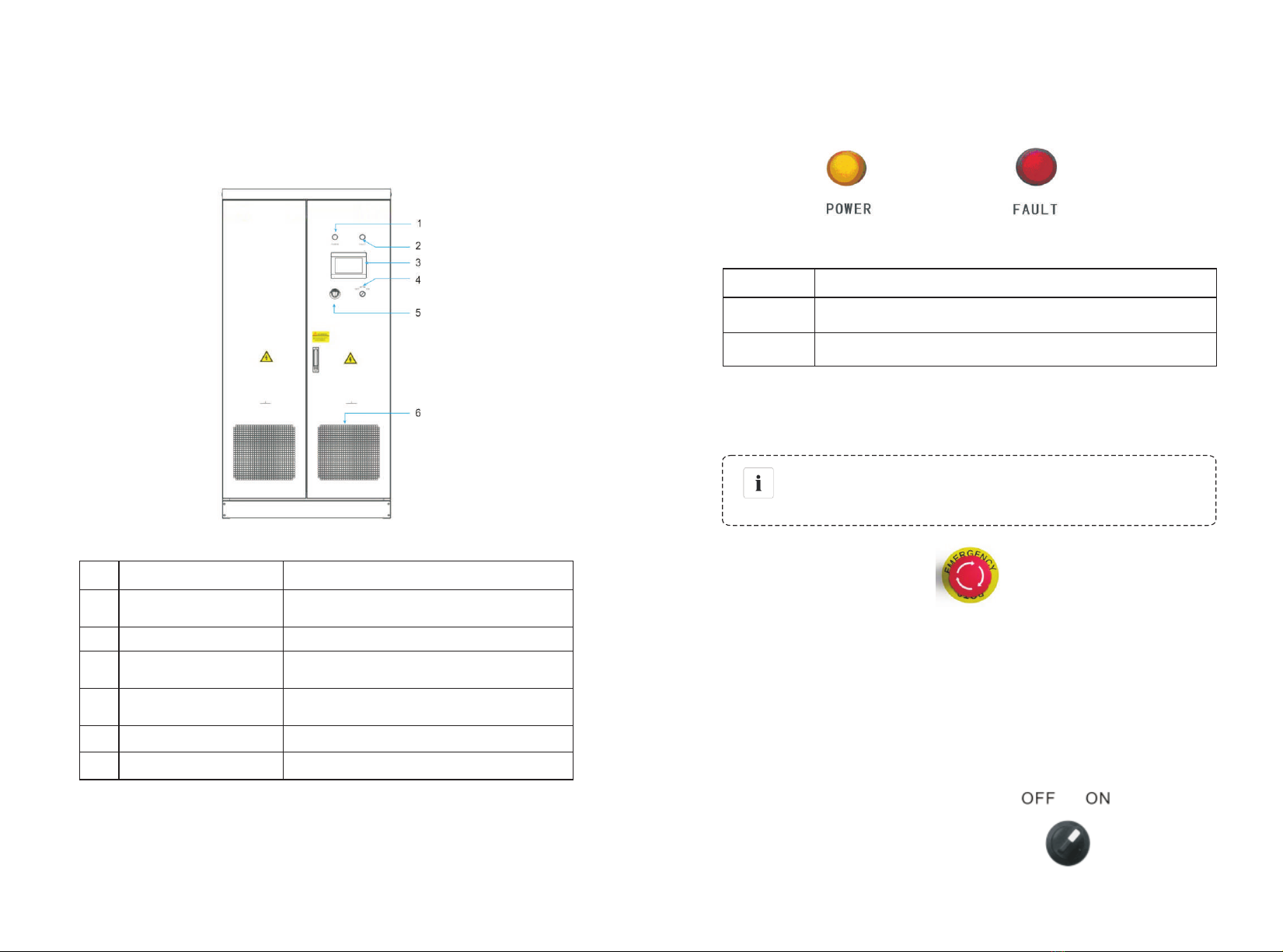
It displays the inverter’s operating parameters, power generation, and faulty
information record. Please refer to Section 6, for details.
Touch screen
3.4.5 PV charger mode
operation logic:
1) PV charges battery individually, does not affect bypass automatic switch
function.
2) After boot, HPS can switch into PV Charger mode automatically if any
anomalies detected.
3) At PV Charger mode, HPS will switch into on-grid mode when grid detected back
to be normal.
4) At PV Charger mode, when grid normal, start the inverter via the LCD, then HPS
run in off-grid mode.
5) At off-grid mode, HPS can stop the inverter and switch into PV Charger mode
3.4.6 On/Off-gird switch
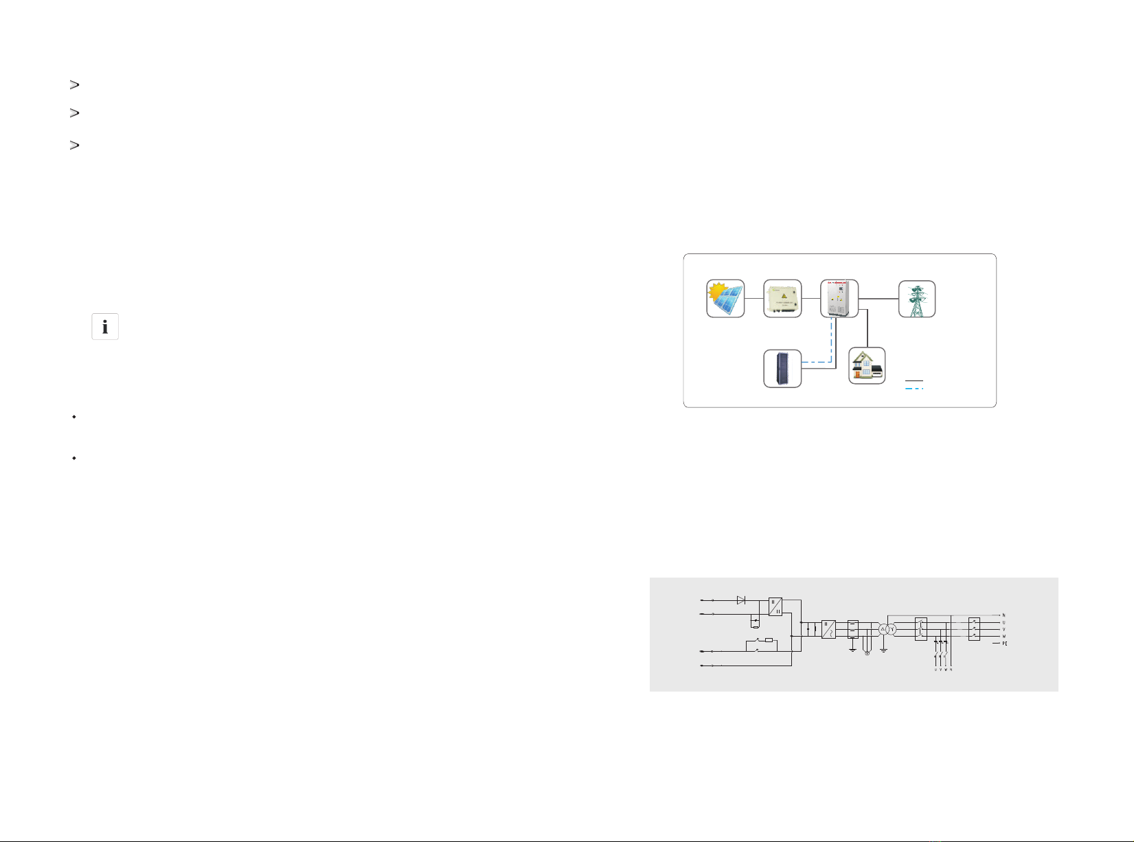
HPS50 connected to battery ,PV on the DC side, and grid,load on the AC side;
Close the ac/dc circuit breaker and start-stop knob, HPS30 enter waiting status;
operation logic:
1) Battery will not discharge when PV power is insufficient, micro-grid will supply
to load and battery
2) operation state
a. When PV power is higher than charging power; PV will supply priority to battery
and the remaining to load. Output power is limited under 50% of load power.
b. When PV power is supply priority to battery, micro-grid charge battery.
3.4.4 Micro-grid backup priority mode (generator mode)
3.4 Operation mode define
3.4.1. Off-grid mode
((1) Grid supplies power to load and charges battery when PV power insufficient.
(2)When the back-flow-prevention works, PV power can meet battery charge and
load power.
(3) operation state
A.PV supply priority to the load, the remaining to load and grid when PV power is
higher than load power
B. When PV power is lower than the charging power, PV supply priority to battery,
the grid supplies to load and battery.
3.4.2On-grid backup priority mode
(1)At this mode, the inverter can prevent the current from flowing back by default,
PV will only need to meet battery charge and load power.
(2)Valley price: working logic is the same to the backup priority mode’s. PV and
grid supply priority to battery, the remaining to load.
(3)Fair price:
A. Battery can neither discharge nor be charged by grid.
B.PV power supply priority to load, the remaining to battery when PV power is
higher than load power.
C. When PV power is lower than load power, PV and grid supply to load.
(4)Peak price:
A. Grid will not charge battery.
B. When PV power is higher than load power, PV supply to load , the remaining to
battery.
C. When PV power is lower than load power, there are two conditions:
a. When battery voltage is normal, PV and battery supply to load.
b. When the battery is under voltage, battery will not discharge, PV and grid supply
to load only, not to battery.
3.4.3On-grid economic priority mode

13
3.7 Storage
If there is a long time before installation or operation, the ATESS HPS50 should be
stored appropriately.
> The packaging should be restored to its original state;
> Retain the desiccant in the packaging.
> The ATESS HPS50 can only be stored when it is stopped and all the doors are
closed in a dry room to protect the internal circuits against dust and moisture.
> Storage temperature range: -40~55 ℃
> Storage relative humidity range: 5 %~95 %
> Operating temperature range: -25~55 ℃
> Operating relative humidity range:5 %~95%
> Max. altitude:2000 m
CAUTION
Strictly prohibited storage without packing!
Avoid storage in direct sunlight!
Keep upright and no stacking on top of the crate.
3.8 Dimension
Dimension 3-8 Inverter dimension
3.9 Packaging information
No. Name Unit quantity description
1
2
3
inverter main unit
user manual
certificate
pcs
pcs
pcs
1
1
1
Contains cabinet keys
Table 3-9 Packaging information
14
3.5 Battery setting
Battery is an important part of energy storage system, strict protection is needed
in the whole operation process. Protection threshold need to be set on HPS50 to
ensure safe operation of battery, parameters including: battery quantity and unit
quantity, capacity, charge current, discharge current, over voltage protection,
under-voltage protection and so on. Battery parameter setting need to be done by
professional personnel. Improper setting of battery will affect the normal
3.6 Protection
Anti-islanding
When the local power grid shutdown due to malfunction or maintenance of
equipment, the inverter will be physically cut off the connection to the grid, in order
to But the HPS30 will go into the off-grid mode and continue to work .There is still
high voltage ,and the staff needs to pay attention to the safety of operation.
Lightning protection
Inverter built-in lightning protection module has the DC / AC side lightning over-
voltage protection to avoid inverter from being damaged.
More protection features, please refer to the section 6.3.

16
4 Products installation
4.1 Installation condition requirements
To ensure normal operation of the machine, the installation environment is
required as follows:
> The ingress protection of inverter is IP20. Moreover, as this product is an
electronic equipment, it shall not be placed in humid environment;
> Install indoors and avoid sunlight and rain;
> Ventilation of the room shall be good;
> The installation environment shall be clean;
> As some noise will be produced in operation, this equipment shall be installed far
from residential quarters;
> The installation ground shall be even enough, and firm enough to support the
weight of inverter;
> The installation position shall be convenient for maintenance;
> Ambient temperature range: –25°C~55°C;
> Appropriate space shall be reserved for the machine to ensure ventilation and
cooling.
We suggest inverter is installed in the distribution room. The floor, wall clearance,
Ventilation equipment and precaution should be designed by professional
personnel and satisfy the following requirements.
[Foundation requirement]
Inverter is required to install on even ground with fire-retardant material as the
surface or channel steel support structure, and sag or tilt ground is prohibited. The
foundation shall be solid, safe and reliable. The foundation shall be capable of
bearing the load of the inverter. Its load bearing ability shall be concerned
throughout the installation place selection.
[Clearance space]
During installation of the inverter, appropriate space shall be left to the wall or
other equipment, in order to satisfy the requirements on narrowest maintenance
channel, emergency access and ventilation.
[Cable trench]
The cable connection of inverter adopts bottom inlet and bottom outlet. Cable
trenches are recommended.
The cable trenches are often designed and constructed by the construction side
based on relevant standards, with the equipment weight and dimensions required
to be considered. Good electrical connection is needed between different cable
trenches and GND terminals.
[Wiring specification]
Cables in the inverter can be classified into either power cables or data cables.
In cabling, the power cable shall be kept far away from, and the cable shall be kept
in right angle at cross. The cable shall be as short as possible, and an appropriate
distance shall be kept to the power cable.
The power cable and data access shall be placed in different cable trenches
respectively to avoid lengthy routing between the power cable and other cables,
so as to reduce the electromagnetic interruption caused by sudden change of the
output voltage. The distance among the power cable and data access shall be
more than 0.2m. When the cables are crossed, the cross angle shall be 90
degrees, while the distance can be reduced appropriately.
[Ventilation requirement]
In operation, inverter will produce a lot of heat. When ambient temperature is too
high, the electrical property of the equipment may be affected, the equipment may
even be damaged. Therefore, the heat release shall be fully considered in
designing the control room to ensure operation of the equipment in high efficiency.
In front of the installation place of inverter, a space of 1.5m or more shall be
ensured, the back 0.6m or more, the top 0.6m or more to ensure easy installation,
cooling and maintenance.
[Ventilation environment]
To satisfy the ventilation requirement of inverter, its installation environment shall
meet the following conditions:
※ Inverter shall be prevented from being installed in the place of poor ventilation
condition and insufficient air flow;
※ The air inlet shall have enough air supplementation.
15

17 18
[Ventilation equipment ]
To ensure safe and reliable operation of the equipment, the ambient temperature
must be within the permission range –25°C~55°C, therefore, appropriate
ventilation devices must be equipped with to release the heat generated by the
equipment. We suggest the ventilation rate is more than 3665m³/h.
·There must be ventilation equipment inside the distribution room to ensure
release of the waste heat generated by the inverter from the equipment, and allow
for maximum ambient environment temperature. This can be realized from
installation of exhaust devices;
·Another fan can be added at the air duct outlet to exhaust the air out and ensure
balanced pressure;
·The direction of the air outlet shall be selected according to the local actual wind
direction;
· Pay attention to the dustproof measures and waterproof design at the air inlet
and outlet;
· If more air ducts are required, its dimensions shall be designed by the
professionals according to the air output amount.
[Other protections]
With IP20 of protection level, inverter is appropriate to be installed in dry and
clean environment. Meanwhile, water leakage of the house shall be prevented, as
it may damage the inverter. According to EMC requirement and noise level, the
inverter shall be installed in industrial environment.
4.2 Tools and spare parts required for whole machine installation
Tools and spare parts required for installation is as follows:
· Hoisting crane, forklift or fork lift truck (with the capacity for bearing the weight of the
inverter)
· Torque wrench
· Screwdriver
· Wire stripper
· Terminal crimping machine
· Heat dryer
· Megger and multimeter
Before the inverter is moved to the designated place, we
suggest to lay the DC input cable and AC main power supply
cable. As these cables are relatively thick, they are hard to
be cabled after the inverter is installed.
4.3 Mechanical installation
【NOTE】
This inverter is transported as an integrated unit, and the user can hoist it from the
bottom with a forklift, or move it with a hoisting crane or crane.
Note 1: The inverter is integrated and cannot be dissembled either in
transportation or installation. Any fault attributed to modification unauthorized by
the ATESS is beyond the quality assurance.
Note 2: In movement, tilt, violent shake or sudden force upon the inverter shall be
prevented, such as sudden down of lifting.
Note 3: Please read carefully the labeled parameters to select an appropriate
transportation means and storage place.
CAUTION!
To keep the equipment in a better protective status, please adopt transportation
with package as much as possible, and comply with the labels printed on the
package in transportation:
4.3.1 Transportation of packaged whole machine
We suggest the user make use of forklift to move the inverter if possible.
Sign Indication
The gravity centre
Lifting logo

19 20
Inverters whose packages are not demolished can be moved with forklift, hoisting
crane or crane. In moving, attention shall be paid to the weight painted on the
package to ensure enough load capacity of the devices. As the gravity center of
the equipment locates at the lower place symmetrical in front and back and left
and right, the support point or hoisting point shall be arranged reasonably in
transportation.
The forklift transportation is the standard one. The gravity center of the cabinet in
transportation should locate between two forks of the forklift. The big-size inverter
may block driver's sight, and it shall be treated with cooperation of the aid
personnel.
Sign Indication
Face up to prohibit the inverter horizontally,
tilted or upside down
Handle with care, to avoid the transport environment
too intense collision friction damage to the inverter
Keep away from moisture
4.3.2 Movement and installation of bare machine
[Demolish the package of inverter]
Please demolish the packaged cabinet of the equipment according to the following
procedures:
Procedure 1: Demolish the wood side and roof of the packaged cabinet
Procedure 2: Demolish the out-set package material on the machine
Procedure 3: Demolish the fastening screws between the machine and the pallet
① Demolish the front and back cover lids of the pedestal;
② Screw off the hold-down nuts at the bottom of the wood pallet;
③ Remove the screws, and the inverter will depart from the wood pallet.
The inverter must be installed on the foundation or foundation plate, therefore, all
fastening points (wall anchor and bolt) must be at their correct positions before
installation. Mounting dimension of foot margin on foundation is shown in Figure.
[Movement and installation of bear machine]
NOTICE
Caution, risk of danger
We must act slowly and gently when transporting the inverter with
forklift to avoid violent vibration of the inverter or collision with
other objects.
Figure 4-3-2-1
The inverter with demolished package can be moved with forklift, hoisting crane,
slide rail or crane.
If the package demolished place is far from the final installation place, it can be
transported with forklift containing wood pallet. It is shown in Figure.
Figure 4-3-2-2

Figure 4-4-2 DC side wiring
4.4.3 AC side wiring
CAUTION!
Caution, risk of danger
When connecting the AC grid, cut off the circuit breaker at the
AC side to ensure that the AC wire connecting to terminals has
no electricity.
Connect AC grid:
1) Cut off the circuit breaker at AC side, to ensure that the AC wire connecting to
terminals has no electricity. Confirm it with a multimeter.
2)Connect the port A marked at "AC-input" of HPS50 with "L1" of the grid .
3)Connect the port B marked at "AC-input" of HPS50 with "L2" of the grid
4)Connect the port C marked at "AC-input" of HPS50 with "L3" of the grid .
5)Connect the port A marked at "AC-output" of HPS50 with "L1" of the load .
6)Connect the port B marked at "AC-output" of HPS50 with "L2" of the load .
7)Connect the port C marked at "AC-output" of HPS50 with "L3" of the load .
8) Connect "N" of the load and "N" of the grid with the "N" port of HPS50
Ensure that the wiring phase sequence at AC side is in consistent with the phase
sequence at grid side.
9) Please confirm that the wiring is fastened.
Figure 4-4-3 AC side wiring
4.4.4 Earthing
Inverter must be earthing well for safety; Please make sure of the connection
between PE in power distribution cabinet and PE copper in the inverter good; and
make sure the earthing cable more than 16mm2 and the earthing resistance must
satisfy the demand of IEC standard.
All wiring into the channel at the bottom of the inverter to be all the wiring is
completed, the connection port must be sealed with dust cotton, to prevent dust
from entering the inside of the inverter.
4.5 Communication
The inverter of ATESS PCS series has various communication methods. When the
user needs to monitor the operating status of DC power generation system, we
provide single-machine and multi-machine control programs, and diversified
communication interfaces for customer's selection.
23 24

2221
4.4 Electrical installation
4.4.1 Input and output requirements
NOTICE
Caution, risk of danger
·There is a danger of electrical shock of high voltage in
inverter ’s operation; only electricians of professional skills can
operate.
·All connections with this equipment shall be done under non-
voltage state.
·The inverter may be damaged if input or output terminal is
incorrectly plugged.
Failure of acting upon this information may cause serious
1) Battery
The positive and negative highest voltage of the battery shall not exceed 1000V,
otherwise, the equipment will be in over-voltage protection state, and cannot work
normally. Recommended battery capacity is 50kWh
Model ATESS HPS50
Recommended battery capacity 50kW.h
Battery Voltage Limit 1000V
2) Three-phase grid
Inverter will continuously inspect whether the grid satisfy the grid connected
conditions. The following is the grid limit for satisfaction of local Grid connected
Conditions (requirements in different countries may vary, the value can be setup
and please refer to local grid connected regulations for details), and the grid is
three-phase grid. Meanwhile, it shall be permitted by local power supply
department before install Grid-connected inverted power.
Model ATESS HPS50
Grid Voltage Limit
Grid Frequency Limit
310Vac~450Vac
45Hz-55Hz/55Hz-65Hz
Cable (Cu) Cable Diameter Requirements (mm²)
Model ATESS HPS30
3) Cable requirements
Aperture
PV and BAT Φ8,20N*m
1 input cable with each 35 mm²
PV and BAT 1 input cable with each 35 mm²
Grid input A B C2
1 input cables with each 50 mm
Communication Wire
0.75mm², shielded Twisted pair is recommended
/
Earth Wire More than 16 mm².Green and yellow is
recommended
2
1 input cables with each 35 mm
2
1 input cables with each 50mm
Φ8,20N*m
Φ8,20N*m
Φ8,20N*m
Φ8,20N*m
Φ8,20N*m
Grid output A B C
N Wire
4.4.2 DC side wiring
CAUTION!
Caution, risk of danger
The positive and negative of the battery shall not be connected
in reverse. A multimeter shall be used to determine the polarity
first, and then connect into the corresponding input ends of the
Specific procedures are as follows:
1) Cut off the distribution circuit breaker at the DC side, and ensure that no
voltage on the wire at DC side.
2) Determine the positive and negative with a multimeter.
3) Connect the positive of the battery to the "Battery-input +"of The HPS50
4) Connect the negative of the battery to the "Battery-input +"of The HPS50
5) Connect the positive of the panels to the "PV-input+" of HPS50
6) Connect the negative of the panels to the "PV-input-" of HPS50
7) Please be sure that all wirings are fastened.

25 26
4.5.1 RS485 communication
The inverter, through RS485 tandem, is connected with the PC for communication
through RS485/RS232 adaptor. Inside the PC, a multi-machine monitoring
software ShineNet independently developed by the ATESS is monitoring in real
time the operating status of all inverters, as shown in Figure 4-5-1. The RS485
wire should be less than 1000m.
Figure 4-5-1 RS485 Multi-machine Communication
4.5.2 Internet communication
There is an Ethernet port on the right side of LCD. Please connect the LCD and
Router with Network cable; and then router can make data interaction with serve,
and users can communicate with the inverter by internet.
Figure 4-5-2 Internet Communication
4.6 Installation inspection
Before the inverter is put into operation, it shall be inspected for installation. Two
working men or more shall inspect to ensure correct installation of all installation
according to the following table.
Inverter's bottom is fixed, and the support is stable and reliable.
Enough space is left around inverter.
The ambient temperature, humidity and ventilation satisfy requirements.
Smooth flow of cooling air.
Complete and reliable sealing protection of cabinet.
No deformation and damage to inverter.
Electrical Installation Inspection
Complete and firm grounding of inverter.
Grid voltage matching the rated input voltage of inverter.
Correct phase sequence of grid connection, and tightening torque meeting
requirements.
Correct connection of DC input anode and cathode, and tightening torque
meeting requirements.
Correct connection of communication lines, and maintaining a certain
distance to other cables.
Mechanical Installation Items Inspection
Other Inspections
All useless conductive parts tied with insulating ribbon.
No tools, spare parts, conductive dust generated from drilling or other
matters left inside the cabinet.
No condensed humidity or icing inside the cabinet.
Table 4-6 Installation Inspection List

27 28
Pilot operation 5
The chapter will introduce the procedure of pilot operation, including checking
battery voltage, input and output connecting, other preparation working.
5.1 Relevant requirements
Before pilot operation, the installation conditions of the equipment shall be
examined thoroughly, in particular whether voltages at DC and AC ends are
consistent with inverter's requirements, and whether the polarity etc. are correct.
Inspect if the system connection meets requirements in relevant standards or
codes and if the system is grounded well.
CAUTION!
Before pilot operation, all switches at AC side and DC side
shall ensure to be cut off.
5.2 Inspection
5.2.1 Inverter inspection
Before power on the inverter, please carry out inspections as the following
procedures:
Procedure 1: Inspect inverter's installation and wiring conditions based on the
Installation Inspection List in Table 4-6;
Procedure 2: Ensure the AC&DC circuit breakers are cut off;
Procedure 3: Ensure the emergency button is available and woks normally.
5.2.2 Grid voltage inspection
Inspect whether the three phases of the inverter is correctively connected with
the three phase sequence of the grid.
Inspect whether the line voltage and frequency are within the prescribed range,
and record the value.
If possible, measure the phase THD (Total Harmonic Distortion), and inspect
the curve. If distortion is serious, the inverter may fail to operate.
CAUTION!
When connecting the load,make sure that the three-phase of
the load is corresponding to the three-phase of the
HPS50,otherwise it will cause the motor to reverse.

29 30
5.4 Pilot operation completion
The following procedures shall be carried out after the inverter is normally in
operation.
Procedure 1: Inspect whether abnormity exists in the inverter, such as excessive
noise, excessive heat, abnormal smell or smoke.
Procedure 2: Measure whether inverter voltage, current and THD are stable.
Procedure 3: Operate LCD control panel and inspect whether it displays normally
and accurately.
By now, the pilot operation of inverter is fully completed, and we can enter the
daily operational maintenance.
5.5 Power off steps
CAUTION!
After the inverter is completely powered off, the general DC
switch at battery side and the Grid switch at grid side still
maintain voltage. If operations are needed, please be sure to
cut off the outer power completely, and wait for not less than 5
1. Click the OFF button on LCD or turn the off-on knob from ON to OFF;
2. Cut off DC SWITCH;
3. Cut off GRID SWITCH;
4. Cut off the switch of DC distribution cabinet or combiner;
5. Cut off the switch of AC distribution cabinet.
5.2.3 DC side voltage inspection
The DC side consists of two parts,from the confluence box or the DC distribution
cabinet to the HPS50 and from the storage battery to the HPS50.
Ensure that the direct current from the confluence box or DC distribution
cabinet is connected to the PV terminal of HPS50 and is in sequence.
Measuring the open circuit voltage of pv-input cannot exceed the allowable
maximum voltage.
Ensure that the direct current from the battery is connected to the battery input
terminal of HPS50 and the polarity is correct.
Ensure that the battery voltage is within the limits set by the HPS50,and the
battery ratio of the HPS50 is correct.
5.3 Power on steps
First power-on
Step 1: Close AC circuit breaker
Step 2: Close DC circuit breaker
Step 3: When powered ,enter the LCD home page
Step 4: Turn the off-on knob from OFF to ON. Click the start button on the screen
after fault indicator puts out. Then inverter will enter a wait state.
Step 5: Inverter will detect whether has been connected to the grid and choose on
or off grid mode
Step 6:When the Battery Storage Inverter is operating in on-grid mode. Click on
the switch button on the top right-corner of the LCD. You can switch between
battery charging and discharging state.
CAUTION!
The HPS50 itself can not switch seamlessly between on and off
grid. That is to say,Cutting into the grid when inverter working
in off-grid mode was forbidden. If intend to use the capability of
switch seamlessly between on-grid and off-grid,you need
additional equipment. If there is a demand please contact us.

31 32
6 GUI instruction
6.1 LCD display screen introduction
User can view the information of the inverter operation on the LCD touch screen,
as well as setting the operating parameters. In order to facilitate the operation, a
menu is provided below.
Table 6-1 ATESS HPS50 LCD Menu
After powering on the LCD,it will enter the home page. Then you can begin to read
the information and set the parameters.
Inverter communication state, station number and system time is displayed at the
top of each page of the LCD.
Each page has five commonly used function keys: "run data" “historical
information” "system settings" “Home” at the below of the page. The five
commonly used keys corresponding sub-menu are under the button, and it will be
marked green after selected.
6.2 LCD operation
6.2.1 Home page
When powered or Clicking “Home” button in any interface will enter into the Home
page.
The operating status of the inverter output power, safety standard, model, input
and output voltage, current information can be viewed in the page. Pressing the
following key can switch to other pages.
6.2.2 ON/OFF interface
Clicking “ON/OFF” button in any interface will enter into this interface.
There are “ON” and“OFF” button which is used to turn on and turn off the inverter.
6.2.3 System setting
Clicking “System setting” button in any interface will enter into this interface.
Submenu: language settings, time settings, inverter information, maintenance.
Pressing the left button can enter into the corresponding submenu interface. The
default one is language setting interface.
Home
Operation
Data History Info On/OffSystem Setup
Time setting
Operation
Data_1 General fault Language
Maintenance
Factory Setting
Operation
Data_2
Charge Power
Chart
Disharge Power
Chart
Energy Chart Charge Month
Generation
Disharge Month
Generation
Charge Year
Generation
Disharge Year
Generation
Charge 20Years
Generation
Disharge
20Years
Generation
HPS30

33 34
Language Settings: Select language, currently it only supports Chinese, English
(default language is Chinese).
Time settings: system time setting (if the date and time displayed on LCD is not
inconsistent with the actual date and time, they can be modified here)
Device Information: This page shows the manufacturer, inverter serial number,
hardware and software version information, and the date of manufacturing.
Maintenance: the interface requires a password to login. It is for electrician and
maintenance personnel who are fully familiar with the structure and working
principle of the DC grid system only, in order to avoid damage to personal safety
and the inverter.
6.2.4 Historical information
Clicking “historical information” can enter into the sub-menu of the "historical
information".
The submenu includes: history of failure.
History of failure: all the common history of failure details can be found by flipping
the page up and down.
The common fault information, see table 6.3.1.

35 36
6.2.5 Operation data
Clicking the “Operation data” in any interface will enter into the submenu of
“operation data”.
The sub-menu includes: real-time data, the power curve, and energy yield figure.
Pressing the left button can enter into the corresponding sub menu interface. The
default interface is the real-time data interface.
Insert USB Disk on the back of the LCD display, and the real time operation data
will be stored in the USB Disk in every minute. Inverter will create a “CSV” format
file every month in the USB disk for data storage.
Real-time data: current DC power generation parameters and real-time data
including the grid voltage, the grid frequency, the grid current, DC input voltage,
DC input current, the internal temperature of the chassis as well as the total power
generation time (updated in real time).
6.3 LCD display information schedule
6.3.1 General history failure table
No. information
1
2
3
4
5
6
7
8
9
10
11
12
13
14
15
16
17
18
19
20
21
22
23
24
25
26
27
28
29
30
31
32
32
33
DC_Inverse_Failure
IGBT_Failure
EEPROM_Write_Failure
EEPROM_Read_Failure
AC_MainContactor_Failure
AC_SlaveContactor_Failure
RISO_Failure
DC_VoltHigh_Fault
DC_CurrHigh_Fault
DC_OCP_Fault
INT_DC_OverVolt_Fault
INT_DC_OverCurr_Fault
IGBT_Module_Fault
L_OCP_Fault
AC_NoUtility_Fault
AC_GridPhaseSeque_Fault
AC_PLL_Fault
AC_Volt_Unbalance_Fault
AC_Curr_Unbalance_Fault
AC_WU_OverVolt_Fault
AC_WU_UnderVolt_Fault
AC_VW_OverVolt_Fault
AC_VW_UnderVolt_Fault
AC_UV_OverVolt_Fault
AC_UV_UnderVolt_Fault
AC_OverFreq_Fault
AC_UnderFreq_Fault
AC_GridCurr_DcHigh_Fault
AC_L_Curr_DcHigh_Fault
AC_OverCurr_Fault
AC_L_Curr_High_Fault
AC_Overload_Fault
AC_Overload_Fault
LVRT_Fault
Table of contents
Other ATESS Inverter manuals
Popular Inverter manuals by other brands

SEW-Eurodrive
SEW-Eurodrive MOVIMOT flexible MMF C/DSI Series operating instructions

Srne
Srne HES4855S100-H user manual

Hoymiles
Hoymiles HMS-800-2T Quick installation guide

Growatt
Growatt SPA TL3 BH-UP Series Installation & operation manual

Generac Power Systems
Generac Power Systems 004810-0 owner's manual

Daikin
Daikin FLXS-BAVMB Service manual