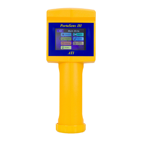
ATI Technologies PortaSens II User manual

PortaSensII
PortableGasLeakDetector
ModelC16
HomeOfficeEuropeanOffice
AnalyticalTechnology, Inc.ATI (UK)Limited
6 Iron Bridge DriveUnit1 &2 Gatehead Business Park
Collegeville, PA19426 Delph New Road, Delph
Saddleworth OL3 5DE
Ph: 800-959-0299 Ph: +44 (0)1457-873-318
610-917-0991
Fax: 610-917-0992Fax: +44 (0)1457-874-468
Email: sales@analyticaltechnology.com Email: sales@atiuk.com

PortaSensII PortableGas LeakDetector, Model C16
O& MManual
Rev-J 7/15-2 -
PRODUCTWARRANTY
AnalyticalTechnology,Inc. (Manufacturer) warrantstotheCustomerthatifanypart(s)
oftheManufacturer's equipment provestobedefectiveinmaterialsorworkmanship
withinthe earlierof 18monthsofthe dateof shipmentor12monthsofthedateofstart-
up, suchdefectivepartswillbe repairedorreplacedfree ofcharge. Inspection and
repairstoproductsthought tobe defectivewithinthewarrantyperiodwillbe completed
at theManufacturer's facilitiesinCollegeville,PA. Productsonwhichwarrantyrepairs
arerequired shall be shippedfreightprepaidtotheManufacturer. The product(s)will be
returnedfreight prepaidandallowed ifit isdetermined bythe manufacturerthatthe
part(s)failed duetodefectivematerialsorworkmanship.
Thiswarrantydoesnotcoverconsumableitems, batteries, orwearitemssubject
toperiodicreplacement includinglampsandfuses.
Gassensorscarrya12monthsfromdateofshipment warrantyandaresubject
toinspectionforevidenceof misuse,abuse,alteration, improperstorage, orextended
exposuretoexcessivegasconcentrations. Shouldinspection indicatethat sensors
havefailed duetoanyoftheabove, the warrantyshall notapply.
TheManufacturerassumesnoliabilityforconsequentialdamagesofanykind,
and thebuyerbyacceptanceof thisequipment will assumeall liabilityforthe
consequencesofitsuseormisusebythe Customer, hisemployees,orothers. A defect
withinthe meaningofthiswarrantyisanypart ofanypieceofaManufacturer's product
whichshall, when suchpart iscapableof being renewed, repaired, orreplaced, operate
tocondemnsuchpieceofequipment.
Thiswarrantyisinlieu ofall otherwarranties(includingwithout limitingthe
generalityoftheforegoingwarrantiesofmerchantabilityand fitness foraparticular
purpose), guarantees,obligationsorliabilitiesexpressed orimpliedbythe Manufacturer
oritsrepresentativesand bystatuteorruleoflaw.
Thiswarrantyisvoidifthe Manufacturer's product(s)hasbeen subject tomisuse
orabuse,orhasnotbeen operatedorstoredinaccordancewithinstructions,orifthe
serialnumberhasbeenremoved.
AnalyticalTechnology,Inc.makesnootherwarrantyexpressed orimpliedexcept
asstated above.

PortaSensII PortableGas LeakDetector, Model C16
O& MManual
Rev-J 7/15-3 -
Table of Contents
PRODUCT WARRANTY ............................................2
SPECIFICATIONS......................................................4
INTRODUCTION......................................................5
PORTASENS II........................................................... 5
PACKAGE CONTENTS .................................................. 6
REFERENCE DRAWINGS ............................................... 6
SMARTSENSOR....................................................12
CHANGING THE SENSOR ............................................ 12
SENSOR RESPONSE TIMES.......................................... 13
GAS INTERFERENCES................................................. 14
OPERATION..........................................................16
QUICK START .......................................................... 16
STARTUP SEQUENCE................................................. 17
GAS CONCENTRATION READING ................................. 18
SOFT KEYS.............................................................. 18
SHUTDOWN............................................................ 18
BATTERIES .............................................................. 19
LED INDICATOR....................................................... 20
RESPONSE TEST ....................................................... 21
INLET AND OUTLET EXTENSIONS ................................. 22
ANALOG OUTPUT .................................................... 22
OPERATING MODES ................................................. 23
Sample Mode.................................................. 23
ALARMS................................................................. 25
LOW FLOW ALARM (“PUMP TROUBLE”)...................... 26
DEVICECONFIGURATION......................................27
VIEWING THE CONFIGURATION................................... 27
CHANGING THE CONFIGURATION ................................ 27
ALARM SETTINGS..................................................... 28
Set Point (S.P.)................................................. 28
Function (FUNC).............................................. 28
DISPLAY SETTINGS.................................................... 31
Range (RANGE)............................................... 31
Blanking (BLANK)............................................ 31
Averaging (AVG)............................................. 31
SAMPLE MODE SETTINGS .......................................... 33
Sampling Time (SAMP).................................... 33
Measuring Time (MEAS)................................. 33
Clearing Limit (CLEAR)..................................... 33
SENSOR CALIBRATION.......................................... 35
ZeroCalibration (ZERO)................................... 35
Span Calibration (SPAN).................................. 35
PRESSURIZED GAS SOURCES....................................... 36
ZERO AND SPAN CALIBRATION STEPS ........................... 36
DATALOGGER...................................................... 38
DATA LOGGER OPERATION AND SETTINGS .................... 38
Clear(CLEAR).................................................. 38
Interval(INT)................................................... 38
C16LOG................................................................ 41
INSTALLATION ......................................................... 41
Installing on Windows 7& 8........................... 41
Installing on Windows XP................................ 41
RS232-to-USBAdapter.................................... 41
Connecting theDevice.................................... 41
STARTING C16LOG .................................................. 42
Version 2.0 and Higher.................................... 42
EarlierVersions............................................... 42
USING C16LOG....................................................... 42
Configure Tab.................................................. 43
Important Note forWindows, Version 7and
Higher............................................................. 43
Download Tab................................................. 45
OUTPUT FILES ......................................................... 46
MAINTENANCE..................................................... 48
Intake Pump Filter........................................... 48
TROUBLE.............................................................. 48
SPAREPARTS........................................................ 49
SMART SENSOR MODULES (MODEL H10).................... 50

PortaSensII PortableGas LeakDetector, Model C16
O& MManual
Rev-J 7/15-4 -
SPECIFICATIONS
Gas Sensor AcceptsH10“Smart Sensor” gassensormodules(not included)
RangeSensordependent (seeSmart SensorModulesonpage 50,orcontact ATI)
Display Backlighted, graphics LCD
AccuracySensordependent (typically±5%ofvalue,limited bycal. gas)
Sensitivity 1%ofsensormodule range
Repeatability ±1%ofsensormodule range
Input/Output RS-232 fortransferoflogged gasreadings
0-1 VDC analog (requiresoptionalcable)
Data Logger1, 5, 10, and15 minute intervals
12,000 samples (8 days@1 minute interval)
C16Log application fortransferring data (CD and Online)
Alarms Three levelalarms, configurable forhighorlowalarm(ordisable)
Lowbatteryalarm
Lowflowrate alarm
Alarmnotificationsprovided byLCDand beeper
Power Primary:D-cellbattery,alkaline recommended, 75 hoursoperation
Backup: Internal,rechargeable battery,6 hours operation
115VAC(std.)batterycharger(220VAC avail.)
Operating Temp. -25ºto +55ºC
Humidity 0-95%Non-condensing
Construction Glass filled nylon, PVC, and stainless steel
Accessories 10”FlexibleWand, Teflon lined
BatteryCharger
(3)Intake Filters
OutletBarbed Fitting
FlowMeter
RS-232 Cable(DB9 Female)
CD (C16Log downloader)
Storage case
Bypass-TFitting (forcalibration)
Shipping Weight 3 lbs. (1.4 Kg.)

PortaSensII PortableGas LeakDetector, Model C16
O& MManual
Rev-J 7/15-5 -
INTRODUCTION
PortaSensII
The PortaSensII isa rugged, hand-helddeviceused to detect leaksoftoxicgas, and also to
detectoxygen displacement ordeprivation.It adaptsquicklyto measure different gassesbyinsertingthe
appropriate gassensormodule. The modulesretainall ofthe calibration and configuration settingsfor
the target gas, such asthe full scale range and alarmsettings.
The device featuresabatterypowered intake pump with a flexible wand forsampling. Readings
and settingsarepresented on a backlighted, graphics LCD, with four“soft keys”,and a beeperto notify
you about alarmsand otherevents.
Readingsmaybe recorded
and transferred to aPCusing a
suppliedapplication, C16Log. The
programoutputsASCII csvfilesfor
importing into applications,like
Microsoft Excel®. The application
operateson MicrosoftWindows®
98,XP,2000, and Windows7 &8.
Formore information, see C16Log
on page 41.
Powerisprovidedfromone
primary(non-rechargeable), D-cell
battery, and switchesautomatically
to a secondary(rechargeable)
batterywhen the primaryis
removed, oritspowerdropsbelow
an acceptablelevel1.
1The internalsecondarybatteryshould be charged priorto useifit hasbeen more than three weeksafter
leaving the factory.

PortaSensII PortableGas LeakDetector, Model C16
O& MManual
Rev-J 7/15-6 -
PackageContents
The following itemsare included.
oPortaSensII GasLeakDetector(Figure1)
oSamplingWand (Figure 2)
oOutletTube BarbedFitting (Figure 2)
oSensorKeeper2(Figure6)
oFlowMeter(Figure7)
oStorage Case
oSpareAlkalineD-Cell battery
oBatteryCharger
oRS-232 Cable
oC16Log CDROM (PCversion, only)
oCalibration“T”
ReferenceDrawings
Figure1. PortaSensII, Front View (ATI-0401)
2H10 sensors are normallyordered separately.

PortaSensII PortableGas LeakDetector, Model C16
O& MManual
Rev-J 7/15-7 -
Figure2. PortaSensII,RearView (ATI-0403)

PortaSensII PortableGas LeakDetector, Model C16
O& MManual
Rev-J 7/15-8 -
Figure3. PortaSensII, Side View (ATI-0402).

PortaSensII PortableGas LeakDetector, Model C16
O& MManual
Rev-J 7/15-9 -
Table1. C16 PortPinAssignments
PinNo. Signal I/O Description DB9 Pinon Cable
03-0201
1 /CTS Input Cleartosend- assert tosuspend deviceoutput. 7
2 /RTS Output Request tosend–assertedbydevicebeforetransmit. 8
3 RX Input Receivedata - devicereceivesdata onthis pin. 3
4 Sig. Com. Signalcommon(note: sameasAOut Com.) 5
Figure4. C16 Port (8-position MINI-DIN, femalereceptacle)

PortaSensII PortableGas LeakDetector, Model C16
O& MManual
Rev-J 7/15-10 -
5 TX Output Transmit data –devicetransmitsdata onthis pin. 2
6 AOut Output Analogoutput –0-1 VDC output,proportionaltogas
concentrationreading:AOut =gas_rdg/sensor_range *
1.0 VDC
N/C
7 N/C Not connected. N/C
8 AOut Com. Analogoutput common(note: sameasSig. Com.) N/C

PortaSensII PortableGas LeakDetector, Model C16
O& MManual
Rev-J 7/15-11 -
Figure5. H10 GasSensorModule (not included)
Replace Battery every Six(6)Months
00-0981 H10 SensorKeeper
Figure6. SensorKeeper
Figure7. Flow Meter

PortaSensII PortableGas LeakDetector, Model C16
O& MManual
Rev-J 7/15-12 -
SMARTSENSOR
The PortaSensII measuresgasconcentration
levelsusing“Smart Sensor”modules,which store their
calibration and configuration settings, suchas,zero,
span, range, and alarmlevels. Thisallowsthemto be
quicklychanged to detect leaksofdifferent toxicgasses,
orto detect oxygen displacement ordeprivation.
The modulesarecalibratedbefore leaving the
factoryand require onlyroutinecalibration,which may
be performed bytrained personnelon site using
traceable gasstandardsand methods. Amore
economicalsolution maybe to return themperiodically
to the factoryforcertified calibration.ContactATI for
detailsabout the “Calibration Certification”programfor
Smart Sensormodules.
Figure8. H10 "SmartSensor"module.
Fourmodulesmaybe kept in the battery-powered,“SensorKeeper” (Figure 6on page11),which
maintainsthe electro-chemicalsensorcell, “on bias”, and readyforuse (recommended).Gassensor
modulesmust be ordered separately. Fora complete list ofmodulesand theiroperatingrange, seeSmart
SensorModules(ModelH10)on page 50.
Note
Sensors maytakeup to 12 hours to stabilize(bias) if not stored inthe SensorKeeper, ornot
installed in the device.
Changing theSensor
Referring toFigure 2 on page 7,loosen the two thumb screwsand remove the flowmanifoldlid
on the rearofthe device. Ifa sensormoduleisalreadyinstalled, grab the sideswith yourindexfinger
and thumb, and pull straight up. Slide the newmoduleinto the recess, connectorfirst, and rotate it to
align the grooveon the sensorwith the guide inthe recess. Press down onthesensorto seatthe
connector. The face ofthe sensormodule shouldbe flushwith the outersurface ofthe recess.
Replace the manifoldlidand hand-tighten the thumb screws. Start the deviceand verifyairflow
through the sampling wand usingthesupplied flow meter. See Figure7 on page 11.
Ifpowerisonwhen the sensorisremoved, the devicedisplays“SENSORMISSING”. At startup,
and whenthesensorisreinstalled with powerapplied,it displaystheentire startup sequence, asdetailed
in the Startup Sequenceonpage 17.

PortaSensII PortableGas LeakDetector, Model C16
O& MManual
Rev-J 7/15-13 -
Sensor Response Times
The tablebelow liststhe time required toobtain readingsof66%,and 90%,ofan instantaneous
exposure tovariousgasses. The timeslisted are forthe sensoronly, and do not include traveltime
through thewand ortubing,ordigitaldamping bythe device. Theyare provided onlyforestimating the
sampling period required fora representative reading.
Table2. GasResponse Times
SENSOR TYPE 66%RESPONSE 90%RESPONSE
Oxidant Sensors(except H
2
O
2
)20 seconds 60 seconds
HydrogenPeroxide 40 seconds 120 seconds
Ammonia30 seconds 120 seconds
Carbon Monoxide 10 seconds 30 seconds
Hydrogen 20 seconds 60 seconds
Oxygen 15 seconds 45 seconds
Nitric Oxide 10 seconds 20 seconds
Phosgene 70 seconds 300 seconds
HydrogenChloride 50 seconds 240 seconds
HydrogenFluoride 50 seconds 240 seconds
HydrogenCyanide 40 seconds 120 seconds
HydrogenSulfide 20 seconds 60 seconds
NitrogenDioxide 10 seconds 40 seconds
SulfurDioxide 10 seconds 40 seconds
HydrideGases 30 seconds 70 seconds
Hydrocarbon Gases 40 seconds 90 seconds

PortaSensII PortableGas LeakDetector, Model C16
O& MManual
Rev-J 7/15-14 -
Gas Interferences
Some sensors exhibit a minorsensitivitytonon-target gasesandvapors. Table3 liststhe cross-
sensitivityfactors ofsensors to various, “interference”gases. To use the table, find the sensortype along
the top, and then scan down thecolumn forthe factorcorresponding to one oftheinterference gases
listed ontheleft. Multiplying thefactortimesthe concentration ofthe interference gasproducesthe
reading that wouldbe displayed bythe device. Forexample, an SO2sensorexposed to 1 PPMofHCN
would producea reading of0.40PPM. See notesfollowingthetable foradditionalcomments.
Table3. Cross-sensitivityFactors
Sensor Type
NH3CI2O3HF HCI HCN H2S SO2CO
H2H2O2
O2
NO NO2Hydride(4)
SiH4COCl2
H-C
NH3-- -0.05
-0.005
CO 0.01 0.005
0.01 0.01 -- 0.1
0.05 -0.05(0.05) 0.08 0.3
H
2
0.002
0.01 0.01 0.0003
0.1 -- 0.03 -0.060.014 0.05
NO 0.08 1.5 0.4 0.08 0.10.09 -- (0.04) 2.0 -0.1 0.8
O2* * * * * * * * -- * * * * *
Cl
2
-0.5 -- 1 2 -0.05 -0.2 -0.4 1.0 -0.01 (-0.1) -0.2 0.1
O
3
0.05 -- 1 -0.05 -0.2 -0.4 1.0 (-0.1) -0.2
HCl -0.5 0.5 -- -0.005 0.02 -0.06(-0.01) 0.05 0.2
HCN 0.1 -0.08
-0.5 -0.1 0.01 -- 0.4 0.1-0.2 0.05(0.2) 0.2 0.5 0.1
HF --
H
2
S1.0 -0.1 -0.1 -0.3 3 -- 6 -5.0 2 2
NO20.08 0.2 0.15 0.2 0.2 0.01 -0.3 -0.1 -- -0.001(-0.1) 0.04 -1 0.1
SO2-0.1 -0.01
-0.011 0.5 0.4 0.08 -- 0.42 -0.8 (0.5) 0.1 0.2 0.4
Hydride
1.5 0.2 0.1 1 6 -3.5 -- 5 2
SiH
4
1.5 0.2 0.1 0.3 6 2 0.005(0.5) -- 2
CO2
CH4
CH
3
SH 0.3 -0.04
-0.03-0.1 1 0.3 2 -1.5 1
C
2
H
2
.0005
0.002 1.7 0.10.1
0.02 0.005
-0.020.0001(0.5) 0.05 1.2
C2H40.002 0.3 0.10.1
-0.01(0.1)0.02 1
C2H6O0.015
0.05 0.02 0.015 0.015
0.1 -0.07(0.02) 0.1 0.7
COCl
2
--
I
nterfere
n
ce
Gas

PortaSensII PortableGas LeakDetector, Model C16
O& MManual
Rev-J 7/15-15 -
Noteson Interference Table:
1. Sensors marked withanasterisk (*)in the oxygen columnare3 electrode sensors that require a minimum of 5%
oxygen tooperateproperly. Hydrogen sensors require oxygen levels at least two times themaximum percent
hydrogenvalue tobemeasured.
2. The data onthe chlorine sensoralsoapplies tobromine,chlorine dioxide,fluorine,and iodinesensors.
3. Data onthe hydridesensorreferstoarsine,phosphine,diborane,hydrogenselenide,and germanesensors.
Response is not exactly 1:1 forallhydrides. Contact ATI fordetails if exact response is needed.
4. Data in ()refers toPPM versionsof the hydride sensors relativetophosphine. Responseis not exactly 1:1 forall
hydrides. Contact ATI fordetails.
5. The sensorcolumnmarked “H-C”stands forhydrocarbonsensors.These includeETO (ethylene oxide), formaldehyde,
alcohol,acetylene,and vinylchloride sensors.
6. Data in thistablerepresentsexposures tolow PPM levels of the interfering gas. Very high concentrations of any
interfering gasmay cause eithershort term orlong term responsefrom a sensor.
7. Interferencefactors may vary oversensorlifetime. Calibrationwithinterferencegasisnot recommendedin most
cases. Contact factory formoreinformation.
8. Empty cells in table indicateinsignificant cross-sensitivity.

PortaSensII PortableGas LeakDetector, Model C16
O& MManual
Rev-J 7/15-16 -
OPERATION
Quick Start
The PortaSensII issimple to operate. Afterremoving the device fromthe storage case, installa
gassensormodule (seeChanging the Sensoron page12)and plug the sampling wand into the inlet port
ofthe manifold (Figure 2 onpage 7).
Note
The “INLET”and“OUTLET”portsonthemanifold must notbe blocked.
To start the device, press and releasebutton 1 (the green button belowthe display). You should
heara beep, and the internalpump shouldbegin run. Ifa sensorisinstalled, thedevice readsthe sensor
memory,performsan internaltest, and presentsthe sensorconfiguration on a numberofreview displays,
before reaching the main display. Otherwise, the pump motoristurned off, and the displayappears as
that shownin Figure10,below.During the startup sequence, you maypress the Skip button to advance
directlyto the main display(the sequenceisshown inStartup Sequenceon page17).
The MainDisplayappears at the end ofthestartup sequence, and isdepictedin Figure9, below.
The gasconcentration reading appears in large, numericdigits,withtheunitsofmeasurement on the
right, andthegassymboljust belowit. The example below showsan ammonia sensorisinstalled, but
the unitsand symboldepend on the installed sensor. The displayalsoindicateswhichbatteryiscurrently
powering the device (see Batterieson page 19 fordetailsaboutthisindication).
Figure9. Main displaywithammonia sensorinstalled.
Figure10 showsthedisplaywhen a sensorisnot installed. Ifa sensorisinstalled at thispoint, the device
willpresent the startup sequence, asdescribed above(and detailed inStartupSequenceon page 17).
Figure10. Sensormissing display.
Note
Aresponse testisrecommended priorto use in the field (see Response Test on page 21).
P
0
PPM
NH3
OFF MENUSMPL
P
SENSOR
MISSING
OFF

PortaSensII PortableGas LeakDetector, Model C16
O& MManual
Rev-J 7/15-17 -
Startup Sequence
The startup sequence fora typicaldevicewith anammonia sensorisshowninthetable below.
The gassymbol,range, and alarmsettingswill varyaccording to the installed sensor.
No. Display Description
D1
LOADING
SENSOR
Uploadingsensorconfigurationand calibration settings.
D2
SELF CHECK
Testinghardwareand software.
D3
SELF CHECK
PASSED
Testscompletedsuccessfully.
D4
100
PPM
NH3
HOLDNEXTMENUSKIP
Rangesetting(full scale).
The“Soft Keys” appearalongthebottomline(see Soft Keys
on page18).
D5
C
-
¯
20
PPM
NH3
HOLDNEXT SKIP
Caution set point.ThelineunderCindicates thecaution
levelisset at -20PPM;thesymbol, ¯, indicates thealarm
activatesat, orbelow, thesetpoint.Alarmoperation is
detailedonpage23.
D6
W
-
25
PPM
NH3
HOLDNEXT SKIP
Warningset point.Theset point is25 PPM, and thesymbol,
-, indicates thealarmactivates at, orabove, theset point.
Alarmoperation isdetailedonpage23.
D7
A
-
50
PPM
NH3
HOLDNEXT SKIP
Alarmset point.Theset point is50 PPM, and thesymbol,-,
indicates thealarmactivatesat, orabove, theset point.
Alarmoperation isdetailedonpage23.
D8
Range 50 PPM
to 500 PPM
HOLDNEXT SKIP
Minimumand maximumrangeofthesensor.
D9
FirmwareRev
Sensor Rev
x.xx
y.yy
HOLDNEXT SKIP
Deviceand sensorrevision levels.
D10
P
0
PPM
NH3
OFF MENUSMPL
MainDisplay showscurrent gasconcentration, unitsof
measure, and gassymbol. Thesymbolintheupperleft
indicates whichbattery isprovidingpower.

PortaSensII PortableGas LeakDetector, Model C16
O& MManual
Rev-J 7/15-18 -
Gas Concentration Reading
The gasconcentration reading appears onthedevice display
with the unitsofmeasure, and the gassymbol. The range setting of
the device determinesthe resolution ofthe reading, asshownin the
table on the right, and isindependent ofthe unitsofmeasure. It isnot
used tolimit, or“clip”, readings, but doeslimit othersettings.
Averaging isusedto stabilize the reading,and Blanking isused to filtersmall reading fluctuationsnear
zero, andsuppress negative readings. See DisplaySettingsonpage 31 fordetailsabout the operation
and configurationofthesesettings.
Soft Keys
The fourpush buttonson the front panelare context sensitive, which meanstheirfunction
changesaccording to the requirementsofthe userinterface. The device normallydisplaysalabeljust
above the button to indicate thefunctionthatwillbe performed when the button is pushed3. The button,
with itsdisplayedlabel,isreferred to asa“softkey”.Throughout thismanual, the term“key”isused most
often to referto the labeled button, and “button”isused whenno labelappears aboveit.
Forexample, during the startup sequenceabove, button 1 (the left most button)islabeled
“HOLD”. It isreferred to asthe “HOLDkey”and isused to halt the displaysequence. Button2 islabeled
“NEXT”. It isreferred to asthe “NEXTkey”and isused to advance tothenextdisplay. Finally,button 4
(the right-most button)islabeled “SKIP”. It isreferred to asthe “SKIPkey”and isused toadvance
directlyto the MainDisplay.
Shutdown
To turn off the device, press and hold the OFF keyon the Main Display,D10,untilthe device
displays, “POWER DOWN”, then release the key.
No. Display Instructions
D10
P
0
PPM
NH3
OFF MENUSMPL
Pressand holdtheOFF key until thedisplay changes to D11
(approximately 3seconds).
D11
POWER
DOWN
Release thekeywhenthisdisplay appears.
3Exceptions tothis arestartingthe device (the displayisnotyet active)and entering Configurationmode (no label
appearsabovethebutton).
Range Resolution
0.00 to 4.99 0.01
5.0 to 49.9 0.1
50 and above 1

PortaSensII PortableGas LeakDetector, Model C16
O& MManual
Rev-J 7/15-19 -
Batteries
The primarybatteryisastandard, alkaline D-cell.It ishousedinthehandle ofthe deviceand will
operate the device continuouslyforapproximately75hours. Ifthe primarybatterybecomesdischarged,
ordisconnected, a secondary(rechargeable)batterywill supplypowerforupto 6 hours. The device
indicateswhichbatteryiscurrentlysupplying powerbythe symbolthat appears inthe upperleft cornerof
the display.
…primarybattery
…secondarybattery
…batterychargerisconnected
Powerisdrawn fromthe primarybatteryfirst. When the primarybatteryislow, the‘P’symbolwill
flash forabout onehour. The devicewilleventuallybeginto beeponceperminute, before switching over
to the secondarybattery.When the secondarybatterislow, the ‘S’symbolwillflash foraboutan hour,
and again the devicewill beep once perminute, before thesecondarybatteryisdischarged. When both
batteriesaredischarged, the instrument willshut off and notrestart untilone orboth ofthe batterieshave
beenrestored.
It isnot unusualforpowerto switchbetween batteriesfora period oftime. The primarybattery
recovers afterbeing switched off, and eventually,recovers enough tobe switched backon. Thisprocess
repeatsforsome time, untilthe primarybatteryisfullydischarged.
AnA/C chargerissuppliedforthe secondarybattery. The jackislocated underthe rubberseal
on the side ofthedevice(see Figure3 onpage 8).When charging, the LEDwill lightsteady.The device
maybe operatedcontinuouslywhile charging.
Warning
Use onlythe battery chargersuppliedbyATIforthisdevice. Connecting a different chargermay
result in permanentdamage to the battery orotherelectroniccomponents.
P
0
PPM
NH3
OFF MENUSMPL

PortaSensII PortableGas LeakDetector, Model C16
O& MManual
Rev-J 7/15-20 -
LEDIndicator
The LED on the panelindicatesbatterystatus. It lightssteadywhen the charge cableis
connected. When the cable isdisconnected, the LED flashesonce everysixsecondsto indicatethe
deviceiscapableofstarting (one,orboth, batteriesare ready). Ifthe LED isoff,both batteriesare
discharged, and the devicewillnot start. In thiscondition, anysensorinstalled in the device maylose
bias,and will require severalhours to stabilizeafterrestoring batterypower.Table 4 summarizesthe
batterystatusindications.
Table4. LEDBattery StatusIndicator
On
(steady)
·Deviceisoff
·Chargecableconnected
·Secondary battery charging
Flashing ·Deviceisoff
·Chargecabledisconnected
·Battery powerisavailableforstart up
Off
(steady)
·Deviceison, or,
·Deviceisoff, chargecableis
disconnected, and no batterypower
isavailable.
Reminder
Keep the sensormodulesin theSensorKeeperwhen not in use.
This manual suits for next models
1
Table of contents
Other ATI Technologies Gas Detector manuals