ATIM Cloud Wireless MR4 User manual

ATIM Radiocommunications
Chemin des Guillets
38250 Villard de Lans
France
ATIM Cloud Wireless
Metering and Dry contacts inputs
MR4
User Guide
Concerned models:
ACW/SF8-MR4
ACW/LW8-MR4

2
ATIM_ACW-MR4_UG_EN_V1.5
Table of contents
DOCUMENT VERSION HISTORY .................................................................................................................................................... 4
DISCLAIMER ................................................................................................................................................................................ 5
TRADEMARKS AND COPYRIGHT ................................................................................................................................................... 5
DECLARATION OF COMPLIANCE................................................................................................................................................... 6
ENVIRONMENTAL RECOMMENDATIONS...................................................................................................................................... 6
A.EXPLOSIVE ATMOSPHERE .............................................................................................................................................................. 6
B.ENVIRONMENT ........................................................................................................................................................................... 6
C.RADIO ...................................................................................................................................................................................... 7
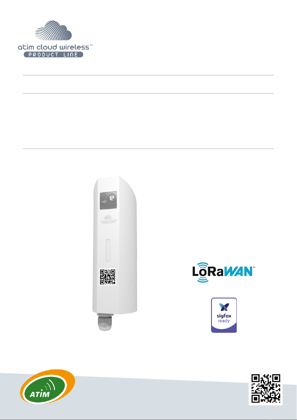
ACW-MR PRODUCT LINE ..................................................................................................................................................................... 8
TECHNICAL SPECIFICATIONS ........................................................................................................................................................ 9
PRODUCT .................................................................................................................................................................................. 9
SENSORS’FUNCTION............................................................................................................................................................................. 9
Input’s characteristics................................................................................................................................................................ 9
CASING ..................................................................................................................................................................................... 10
FOOTPRINT.............................................................................................................................................................................. 10
FASTENERS .............................................................................................................................................................................. 11
PRODUCT IDENTIFICATION........................................................................................................................................................... 11
INSTALLATION AND DISMANTLING ................................................................................................................................................. 12
INSTALLATION........................................................................................................................................................................... 12
CONNECTOR MAPPING .............................................................................................................................................................. 13
OPERATING............................................................................................................................................................................... 14
MODE OF OPERATION ................................................................................................................................................................ 14
PUTTING THE PRODUCT INTO SERVICE............................................................................................................................................ 15
SENDING A TEST FRAME.............................................................................................................................................................. 16
DEEP SLEEP.............................................................................................................................................................................. 16
RADIO MODULE ACTIVITY ............................................................................................................................................................ 16
THRESHOLD EXCEEDED ............................................................................................................................................................... 16
ANTI-FRAUD SYSTEM.................................................................................................................................................................. 17
SUBSTITUTION TO THE MAGNET.................................................................................................................................................... 17
BATTERY PASSIVATION................................................................................................................................................................ 17
ACW CONFIGURATOR................................................................................................................................................................ 18
A.COMPATIBLE CONFIGURATOR VERSION .......................................................................................................................................... 18
............................................................................................................................................................................................. 19
B.ACW-MR4 SETUP.................................................................................................................................................................... 19
Emission period and samples in the frame ............................................................................................................................... 19
Keep alive frame period ............................................................................................................................................................ 20
Frame timestamp ..................................................................................................................................................................... 20
Product clock ............................................................................................................................................................................ 21
Product versions ....................................................................................................................................................................... 21
Inputs configuration ................................................................................................................................................................. 21
Metering thresholds setup........................................................................................................................................................ 22
Meters overview ....................................................................................................................................................................... 22
Setup validation........................................................................................................................................................................ 22
C.FACTORY SETTINGS .................................................................................................................................................................... 22
D.UPDATES OF ACW.................................................................................................................................................................... 23
FRAMES FORMAT...................................................................................................................................................................... 24
SIGFOX AND LORAWAN ............................................................................................................................................................ 24

3
ATIM_ACW-MR4_UG_EN_V1.5
Classic frame............................................................................................................................................................................. 24
Measurement frame................................................................................................................................................................. 25
Specific case: In and out configured in Edge mode .................................................................................................................................26
Alert measurement frame......................................................................................................................................................... 27
Keep alive frame ....................................................................................................................................................................... 28
Error and alarm generic frame................................................................................................................................................ 29
MR4 specific frame ................................................................................................................................................................... 30
EXAMPLES OF FRAMES................................................................................................................................................................ 32
Measurement frame................................................................................................................................................................. 32
Alert measurement frame ....................................................................................................................................................... 32
DOWNLINK ............................................................................................................................................................................... 33
CONFIGURATION OF THE FRAME PARAMETERS (SENDING PERIOD,NUMBER OF SAMPLES,ETC.).................................................................. 33
INPUTS SETUP........................................................................................................................................................................... 33
THRESHOLD COUNTERS SETUP...................................................................................................................................................... 34
INPUT BOUNCE TIME CONFIGURATION ........................................................................................................................................... 34
COUNTER VALUE CHANGE........................................................................................................................................................... 35
TECHNICAL SUPPORT................................................................................................................................................................. 36

4
ATIM_ACW-MR4_UG_EN_V1.5
This user guide is applicable to the following references
Document version history
Version
Date
Description
Author
Software
version
0.1
23/01/2020
Document creation
AC
V0.0.1
0.2
28/02/2020
Current consumption addition
AC
V0.0.1
0.3
05/03/2020
Correction
AC
V0.0.1
0.4
10/03/2020
Add connector mapping
AC
V0.0.1
0.5
25/03/2020
Correction on measurement frame
AC
V0.0.1
0.6
15/04/2020
28/04/2020
Endianness modification of the fields of the
frames.
Modification of LED/Buzzer sequencies and
magnet usage
YLB/AC
V0.0.1
0.7
06/05/2020
Terminal block wiring update
Document title modification + operation mode
Error code correction
AC/YLB
V0.0.1
0.8
07/09/2020
Keep alive frame description + product error
codes addition
AC
V0.0.2
0.9
23/10/2020
Batteries passivation description
AC
V0.0.3
0.10
10/12/2020
Datalogging downlink frame description
correction
AC
V0.0.4
0.11
21/01/2021
Compatibility mode regarding repeaters
LoRa/LoRaWAN and FSK/Sigfox description
Modification of the operation mode
description: LED behavior when searching for a
network
YLB
V0.0.6
1.0
29/01/2021
Minor corrections
FR
V0.06
1.1
16/06/2021
Datalogging downlink corrections
AC
V1.0.0
1.2
22/06/2021
Text formatting
AC
V1.0.0
1.3
09/07/2021
Add input’s characteristics
AC
V1.0.0
Product references
Product version
(Visible on the label of the
product)
LoRaWAN
ACW/LW8-MR4
A.2
Sigfox
ACW/SF8-MR4
A.2

5
ATIM_ACW-MR4_UG_EN_V1.5
1.5
02/06/2022
Change measurement frame
Add downlink command to change counter
index
YLB
V1.0.4
Disclaimer
The information contained in this document is subject to change without warning and does not represent a
commitment on the part of ATIM radiocommunications. ATIM radiocommunications provides this document ‘as-is’
with no warranty of any kind, express or implied, including but not limited to implied warranties of merchantability or
fitness for a particular purpose. ATIM radiocommunications may make changes and/or improvements to this manual
or to the product(s) or program(s) described in this manual, at any time.
Trademarks and copyright
ATIM radiocommunications®, ACW ATIM Cloud Wireless® and ARM Advanced Radio Modem® are registered
trademarks of ATIM SARL in France. The other trademarks mentioned in this document are the property of their
respective owners.

6
ATIM_ACW-MR4_UG_EN_V1.5
Declaration of compliance
All ACW Atim Cloud Wireless®products comply with the regulatory requirements of the R&TTE Directive
(1999/5/EC), article 3:
1 SAFETY (Article 3.1a of the 1999/5/EC Directive)
NF EN60950-1 Ed. 2006/A1:2010/A11:2009/A12:2011 (health)
EN62479: 2010 (power <20mW) or EN62311:2008 (power > 20mW)
2 Electromagnetic Compatibility (Article 3.1b of the 1999/5/EC Directive)
EN 301489-3 v1.4.1, EN 301489-1 V1.9.2
3 Efficient use of the radio frequency spectrum (Art.3.2 of the 1999/5/EC Directive)
ETSI EN300 220-2 v2.4.1 and EN300 220-1 v2.4.1
The modemsof the ACW range are part of the radiocommunication modems using the ISM (Scientific Medical Industry)
bands which can be used freely (free of charge and without authorization) for industrial, scientific and medical
applications.
Environmental recommendations
a. Explosive atmosphere
Except for the ACW-ATEX line specifically intended for this purpose, do not use ACW radio modems in the presence of
flammable gases or fumes. Using the equipment in such an environment constitutes a safety hazard.
b. Environment
Respect the temperature ranges for storage and operation of all products. Failing to respect these guidelines could
disrupt device operation or damage the equipment. ACW products in IP65 water- and dust-resistant housings may be
placed outdoors, but must not, under any circumstances, be submerged.
Follow the instructions and warnings provided below to ensure your own safety and that of the environment and to
protect your device from any potential damage.

7
ATIM_ACW-MR4_UG_EN_V1.5
Waste disposal by users in private households within the European Union. This symbol appears on a product or
its packaging to indicate that the product may not be discarded with another household waste. Rather, it is your
responsibility to dispose of this product by bringing it to a designated collection point for the recycling of electrical
and electronic devices. Collection and recycling waste separately at the time you dispose of it helps to conserve
natural resources and ensure a recycling process that respects human health and the environment. For more
information on the recycling centre closest to your home, contact your closest local government office, your local
waste management service or the business from which you purchased the product.
c. Radio
Modems in the ACW line are radio-communication modems that use the ISM (industrial, scientific and medical)
bands, which may be used freely (at no cost and with no authorization required) for industrial, scientific and medical
applications.
General hazard –Failure to follow the instructions presents a risk of equipment damage.
Electrical hazard –Failure to follow the instructions presents a risk of electrocution and physical injury.
WARNING: do not install this equipment near any source of heat or any source of humidity.
WARNING: for your safety, it is essential that this equipment be switched off and disconnected from mains
power before carrying out any technical operation on it.
WARNING: the safe operation of this product is ensured only when it is operated in accordance with its intended
use. Maintenance may only be performed by qualified personnel.

8
ATIM_ACW-MR4_UG_EN_V1.5
ACW-MR Product line
ACW-MR product line regroups different types of radio equipment which allow pulse metering, dry contacts and fraud
detection.
Each device of this product line is available in LoRaWAN and Sigfox version and are delivered with removable batteries.
They can be parametrized through intern switches or via downlink frames on the network (exclusively on LoRaWAN
version).
ACW-MR4
The ACW-MR4 is a sensor used for remote metering monitoring (gas, water, electricity, pluviometer
meters…) or for remote bang-bang equipment control (eg: starting up/shutting down,
opening/closing...).
This sensor can be connected to 4 independent equipment when they are close enough, allowing
devices and network plans savings.
The ACW-MR4 is delivered with two Lithium 3.6V removable batteries packs with a total capacity of
14400 mAh.
CAPT-OPT2 & CAPT-MECA
In addition to the ACW-MR4, there are 2
metering sensors options: an integrated optical
sensor, this plug and play device monitors
remotely the consumption of an LED optical
electrical meter (eg: Linky meters, PME-PMI
meters) or an integrated mechanical sensor
which traduces the rotation of the meter index
into pulses and then to energy consumption. It
is delivered and pre-set to memorize the
consumption index every 10 minutes and send
the last 6 every hour.
CAPT-DOCK
In addition to the ACW-MR4, there is an industrial detector opening/closing
door/window/trap. Coupled with an ACW-MR4, it comes wired and
preconfigured for immediate installation. This sensor is generally used for
intrusion detection. It is also suitable for monitoring Skydome openings or for
checking the presence of objects in their parking area. Data is sent through
LPWAN technologies (Sigfox / LoRaWAN).

9
ATIM_ACW-MR4_UG_EN_V1.5
Technical specifications
Product
Dimensions
154 x 54 x 54 mm
Antenna
Integrated (1/4 of wave)
Temperature
-25°C to +70°C (Operating mode)
-40°C to +70°C (Storage)
Mounts to
Wall, tube or mast, DIN-Rail
Casing
IP 65
Power Supply
2x packs of Lithium AA batteries
Weight
300 g
Frequency
865 –870 MHz
Power
25 mW (14 dBm)
Rate
Sigfox: 100 bits/s
LoRAWAN: 300 bits/s to 10 Kbits/s
Consumption
Mode Tx
Sigfox
LoRaWAN
60 mA
55 mA
Mode veille
< 90 µA
< 90 µA
Mode Rx
50 mA
25 mA
Sensors’ function
4 digital inputs with edge detection or pulse metering.
Input’s characteristics
MIN.
TYP.
MAX.
Working voltage (Volts)
0
3.3
30
Input high level voltage (Volts)
2.3
-
-
Input low level voltage (Volts)
-
-
0.4
Frequency (Hz)
400
Bounce filtering time (ms)
1
255

10
ATIM_ACW-MR4_UG_EN_V1.5
Casing
Footprint
Maximum diameter of the cable in the stuffing box: 7 mm.

11
ATIM_ACW-MR4_UG_EN_V1.5
Fasteners
ACW modems are fixed on a flat wall, a mast or on a DIN rail depending on the type of installation desired.
These three types of fasteners are plugged into the back of the case.
Fixing on a flat wall (supplied):
On tube or mast:
DIN rail mounting:
Product Identification
The Sigfox or LoRaWAN IDs of the product are visible on the outside label on the back of the product, inside on the
electronic card, and in the status section of the ACW configurator.
For LoRaWAN modems, the communication keys are automatically given by the network (pairing by "Over The Air
Activation", or OTAA).
MR4
Serial product
number
Product ID
Revision number of the product
(Hardware version, Application
software/radio firmware)
Product reference
DevEUI LoRaWAN
Datamatrix
ACW-MR4 label

12
ATIM_ACW-MR4_UG_EN_V1.5
Installation and dismantling
It is necessary to open the box to access on the one hand the micro-USB port
allowing the configuration of the module and on the other hand to the connection
terminal block.
To do this, you must insert the screwdriver into the slot and tilt it downwards to lift
the internal tab (see photo opposite). Then pull on the back side to separate the two
parts of the case.
Installation
Install the modem at a minimum height of 2m and not glued to the wall, ideally offset at least 20cm Cables must not
exceed 10m in length and must be shielded
For optimal results, it is advised to place it high and clear of any metallic obstacle within a radius of 1 meter if possible
(see figures below). For information, the antenna is integrated in the box.
Opening slot
2m

13
ATIM_ACW-MR4_UG_EN_V1.5
Connector Mapping
The connector mapping is as follows:
VCC
GND
IN4
IN3
IN2
WIRECUT
IN1
GND

14
ATIM_ACW-MR4_UG_EN_V1.5
Operating
Mode of operation
The new generation 2020 ACW (Atim Cloud Wireless®) products are all based on the same internal software
(Firmware) and bring interesting new features such as the selection and visualization of their operating mode. To know
the status of the product, you just must pass a magnet briefly (<2 sec) against the QRCODE label or on the Pepper
boxes against the small diamond, which causes the LED indicator of the corresponding color to light up:
→→→→
Deep sleep mode: When you take the product out of its packaging, it is by default in this deep sleep mode, which
optimizes the life of the batteries by avoiding their oxidation. The product does not transmit and waits patiently
for you to wake it up.
Network pairing mode: This mode is active as soon as the product leaves the deep sleep mode and allows the
pairing to a network (automatic in case of battery change).
Configuration mode: this mode is active 5 minutes after the exit of the deep sleep mode and authorizes the
configuration of the product in Bluetooth thanks to the PC configurator or to the mobile application ATIM. During
these 5 minutes messages are sent by radio every minute (5 "radio frames"), that allows you to check that the product
works well, for example after having placed it under a cast iron manhole. After this period, the product goes into
operation mode and the Bluetooth is deactivated (possibility to reactivate it via Downlink).
Operating mode: this is the default mode after the product start-up phase. In this mode, the module periodically
sends measurements according to the configuration applied (if the product has never been configured, the
factory configuration applies, see Factory Configuration).
Internal fault mode: This mode allows the normal operation of the module to be interrupted when a critical
event occurs. The nature of the event can be multiple:
•Battery empty (Battery voltage < 2.2V)
•Internal error of the radio module
•System error
The entry in this mode "Internal fault" is signaled by a RED flashing of the LED of the product
If the error does not come from the radio module, the product will send 3 radio frames every 24 hours containing the
error code(s) (see chapter Frame Format for error codes). In addition, the product will emit a warning light depending
on the nature of the event.
Once in this mode, the module must be restarted (by disconnecting and then reconnecting the battery, by Downlink
command or with the magnet) to regain normal operation.

15
ATIM_ACW-MR4_UG_EN_V1.5
Putting the product into service
Unless otherwise requested, ACW products are delivered with batteries connected and set to "deep sleep"
mode.
To place the product in its operating mode, hold a magnet against the QRCODE label for 6 seconds. During these six
seconds, the product's LED should blink WHITE and then GREEN at the end of the six seconds to indicate that the
product has been successfully switched on.
The ACW then enters the network pairing phase. During this phase, a FUSCHIA light signal with a fade effect
indicates that the search phase is in progress.
If the connection is successful, the product will emit a light signal indicating the quality of the network:
GREEN light signal: good network quality
•YELLOW light: average network quality
•ORANGE light: low network quality
•WHITE light: no information on network quality
The module will then enter its operating mode and start sending information to the network according to the
configuration.
NOTE
The LoRaWAN version, if it fails to connect, will go into simple sleep mode and make the next pairing attempt the next day and
every day until it successfully joins the network.
Special case
For a Sigfox product
•To have the information on the quality of the Sigfox network (GREEN, YELLOW or ORANGE light signal), it is
necessary to provide a Sigfox Downlink. It is this one which will allow to rule on the quality of the network.
The product emits at startup a test Uplink described in the chapter Classic frame (frame type 0x02). If a Sigfox
Downlink is provided, the information on the network quality will be sent back by the ACW (light signal). If no
Downlink is provided, the ACW will always display the WHITE light signal at the end.
•If a WHITE light signal is emitted by the product at the end of the 5min pairing phase and a Downlink has been
provisioned, it means that the Network is not accessible.
•If a WHITE light at the end of the 5min pairing phase is emitted by the product without a downlink having been
provisioned, this has no meaning as to the quality of the network. The network quality can be good or bad (or
non-existent).

16
ATIM_ACW-MR4_UG_EN_V1.5
For a LoRaWAN product
•In the default LoRAWAN Class A operating mode, (see Radio settings chapter), if at the end of the 5 minutes
pairing phase, no network has been reached, then the product goes into standby and will restart a 5-minute
pairing phase 24 hours later. So, if the product is placed in an area not yet covered by a network, the product
will join it when connectivity is possible. There is no need to intervene on the product for it to join the
network.
•In the LoRa/LoRAWAN Repeater Compatibility operating mode, (see chapter Radio parameters), if at the end
of the 5 minutes of the pairing phase, no network has been reached, then the product emits a WHITE light
signal and enters its nominal operating mode. Even if no network has been reached, it is assumed with this
mode that an ATIM LoRa/LoRAWAN repeater located nearby will be able to repeat the Local frames emitted
by the product in LoRAWAN frames on the network that the repeater has reached.
Sending a test frame
When the product is in its operating mode (and only in this mode), it is possible to send a test frame (which
avoids waiting for the next measurement frame) including a measurement sample.
To do this, simply move the magnet against the QRCODE label, which turns the LED GREEN and wait for it to go out
before removing the magnet. The successful sending of the test frame will be indicated by a CYAN light signal.
Just before sending, a leak detection is performed, and a value of this measurement is integrated in the frame. This
ensures that the cable or the electrodes are correctly installed. The test frames are identical to the alert frames. See
their structure in the "Alert frames" section.
In the case of a cable without the "Distance measurement" option (yellow and black cable). The measured value should
be close to zero.
Deep sleep
When transporting or storing the ACW-WL, it is best to place it in its deep sleep mode to limit unnecessary power
consumption.
From any operating mode (except fault mode), move a magnet against the QRCODE on the case for 6 seconds.
During these six seconds, the product's LED will flash the color corresponding to the operating mode and then
the end of the sequence will be indicated by a WHITE fade acknowledging that the product has been put to sleep.
The magnet can then be removed.
Radio module activity
Any radio frame transmission is normally indicated by three short flashes of GREEN color of the LED. This function is
disabled by default on all products with a front panel LED, such as the ACW-THAQ and ACW-WL.
Threshold exceeded
When thresholds have been configured using the configurator and the measurement values exceed these thresholds,
the product's LED emits a periodic ORANGE flash to notify this. This function is disabled by default on all products with
a front panel LED, such as the ACW-THAQ and ACW-WL.

17
ATIM_ACW-MR4_UG_EN_V1.5
Anti-fraud system
A mechanism (push button) is present on the product to notify any opening of the case during normal operation.
In normal times, the box presses the button. As soon as the back cover is removed, the button is released, triggering
the fault mode of the ACW-MR4. A light signal indicates that the opening of the case has been considered.
In addition, if the module is connected to a network, an error frame will be sent every 24 hours until its next restart.
Substitution to the magnet
You can use the push button on the ACW-MR4 card to perform the same actions as the magnet (activate or deactivate
the product, activate / deactivate Bluetooth).
To do this, open the case and exert two simultaneous presses on the push button. A white flashing indicates that the
button now acts as the magnet (button pressed = magnet approached, refer to Product commissioning, Test frame,
Deep sleep above to find out how to use the button).
WARNING
Once the manipulations have been completed, press the button again two times to restore it to its main function. A white
flashing indicate that the manipulation has been successful.
Battery passivation
The ACW-MR4 incorporates a battery depassivation feature, to limit the phenomenon of battery passivation during
prolonged phases of deep standby. This feature is automatically activated as soon as the product goes into its deep
sleep mode. The product will then be awakened once a day to start the battery depassivation sequence, then the
product will return to deep standby by itself.

18
ATIM_ACW-MR4_UG_EN_V1.5
ACW configurator
a. Compatible configurator version
For an MR4 with the following application software version:
Use the version of ACW Configurator:
Sigfox: V0.0.1
LoRaWAN: V0.0.1
V5.1.0
Download and install the configuration software setup “setupACW.exe”at:
https://www.atim.com/wp-content/uploads/documentation/CONFIGURATEUR/ACW/configurateur-acw.exe
NOTE
The product must be in its configuration mode to be detected by the configurator. For safety reasons, configuration is only
possible for 5 minutes after the product has been started. First, the product must be put into deep sleep mode (magnet close
for 6 seconds), wait about 20 seconds for the entry into deep sleep to be effective, then wake up the product (magnet 6 seconds
again). The product can then be configured.
When the ACW Configurator is launched, the waiting
window appears on the screen.
Click on "Help" at the top left of the window then on
"About" to display the version number of the ACW
configurator
Pairing the ACW-MR4 with the configurator can be done in two ways:
•By USB: open the case of the ACW-MR4 and connect it to a computer with a micro-USB cable.
•By Bluetooth: make sure that Bluetooth is activated.
WARNING
Do not leave the product connected to the configurator (via USB or Bluetooth) unnecessarily, otherwise the autonomy of the
product will be seriously degraded.

19
ATIM_ACW-MR4_UG_EN_V1.5
b. ACW-MR4 setup
Emission period and samples in the frame
The transmission period corresponds to the time interval between each sending of a measurement frame. This
period can be configured from 10 min to 255 h and its default value is 1 hour.
In addition, it is possible to configure the number of samples in a frame . Thus, several measurements will be carried
out before the sending of the frame which will contain all these measurements.
For example, with a period of 12 minutes and a number of samples of 4, a measurement will be made every 3 minutes
and the 4 samples will be sent in a single frame every 12 minutes.
Finally, it is possible to apply a redundancy of the data , which means that samples having been sent in the frame
n-1, n-2 or n-3 could be sent again in the frame n to the continuation of the new measurement samples (the most
recent sample first in the frame and the least recent last).
For example, for a history depth of 3, the data of the last 2 frames will be sent, in addition to the new data, in the next
frame.
1
2
3
1
2
3
4
5
6
7
8
9
10
11
12

20
ATIM_ACW-MR4_UG_EN_V1.5
Keep alive frame period
A life frame can be sent periodically . This frame will raise the supply voltage of the product.
The value of this period can be configured from 1 hour to 1 month. By default, the value is set to 4 days.
Frame timestamp
It is possible to deactivate / activate the time stamping of all radio frames .
WARNING
This option when activated monopolizes 4 bytes in the frame which cannot be used for useful data.
Radio parameter
The device can work in 3 different operating modes :
For a LoRaWAN device
1. LoRAWAN Class A (default): The product is modulated in LoRa and uses the LoRAWAN Class A
protocol. This is the product's default mode. This mode requires a private LoRAWAN network (private
gateway), or an operated network to view the data sent by the product.
2. Local mode : Product modulation remains LoRa modulation. However, there is no LoRAWAN overlay.
In this mode, you must choose the radio channel on which the product will transmit. To be able to
receive the product frames, a radio modem with the same parameters is then required. This mode
has no real concrete use case for the moment, but future developments of this mode will provide
interesting point-to-point features.
3. Compatibility mode with the ATIM LoRa / LoRAWAN Repeater: This mode should be selected when
you want to operate in classic LoRAWAN, but no network (private or operated) is accessible. This
mode, associated with the ATIM LoRa / LoRAWAN Repeater, then makes it possible to join the
LoRAWAN network through this repeater. In this mode, if the network is not joined (no JOIN_ACCEPT),
then the product will send its frames locally. The LoRa / LoRAWAN repeater then relays these frames
on the network that it has joined (the repeater must be placed at a location with connectivity to the
desired network).
IMPORTANT NOTE
If the product has access to the LoRAWAN network, the default operating mode (LoRaWAN Class A) must be used. If this mode
is chosen, while the network is accessible, the product will still send a frame over the LoRAWAN network and this same frame
in Local mode to the Repeater, which will consume battery unnecessarily.
4
5
6
Other manuals for Cloud Wireless MR4
1
This manual suits for next models
4
Table of contents
Other ATIM Analytical Instrument manuals
Popular Analytical Instrument manuals by other brands

Olympus
Olympus IPLEX G Lite Operation manual

Invacare
Invacare IRC450 user manual

Extech Instruments
Extech Instruments HDV WTX2L Product sheet

Keysight
Keysight x series Installation note

Powerfix Profi
Powerfix Profi PEK 2.3 A1 User manual and service information

Milwaukee
Milwaukee M-Spector 360 Operator's manual