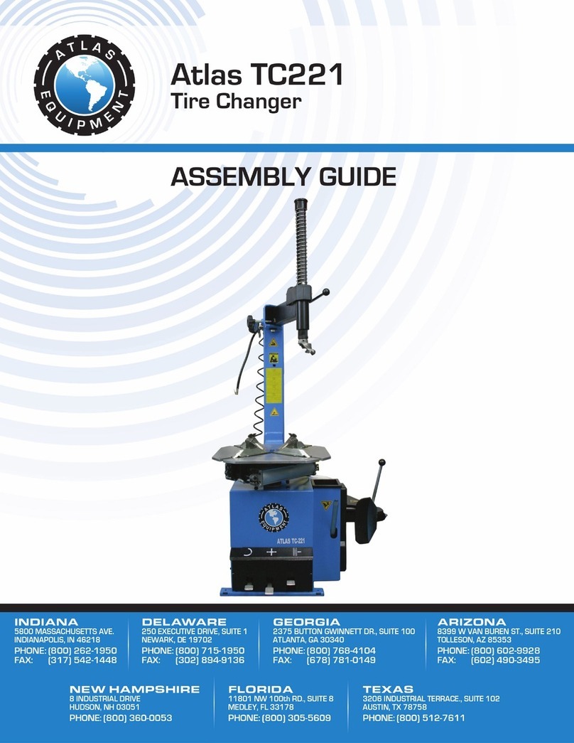
Atlas Equipment TC589X User manual

1

2
INDEX PAGE
Technical Specifications ..................................................................................................................3
General Safety Warnings .................................................................................................................4
Specific Product Warnings And Precautions ...................................................................................6
Assembly Instructions......................................................................................................................7
Transport
Unpacking
Product Description
Workplace Requirements
Assembly Procedure
Pneumatic Link Up
Electric Link Up
Warning Label................................................................................................................................13
Operating Instructions....................................................................................................................14
To Perform Preliminary Operating Texts
How to Break the Tire Bead
Demounting the Tire from the Wheel
Mounting the Tire onto the Wheel Rim
Inflating the Tire
FRL Instructions ............................................................................................................................20
Routine Maintenance .....................................................................................................................21
Troubleshooting Guide ..................................................................................................................22
Mounting Head’s Angle Adjusting.................................................................................................23
IP Version.......................................................................................................................................24
Exploded Drawings And Spare Parts List......................................................................................29
Electric Schematic .........................................................................................................................40
Pneumatic Schematic.....................................................................................................................43

3
ITEM DESCRIPTION
Electric Requirements..........................................................................................120volt 60 Hz 1ph
Max. Wheel Diameter................................................................................................ 46″(1168mm)
Max. Wheel Width .......................................................................................................15″(380mm)
Outside Clamping – Rim Sizes............................................................................................ 12″~25″
Inside Clamping – Rim Sizes............................................................................................... 13″~27″
Max. Bead Breaker Opening........................................................................................13″(330mm)
Max. Inflation Pressure........................................................................................... 145 PSI (10 bar)
Bead Breaker Force........................................................................................... 5500 LB. (2500kgs)
Max. Rotating Torque (Turntable) ...................................................................795 ft·lbs (1078N·m)
Noise Level .............................................................................................................................<70dB
Overall Dimensions (L×W×H) ................................. 60″×60″×84″(1524mm×1524mm×2146mm)
Net Weight ..............................................................................................................675Lbs. (306kg)
THE MANUFACTURER RESERVES THE RIGHT TO CHANGE
PRODUCT SPECIFICATIONS WITHOUT NOTICE.
PICTURES OF PRODUCTS IN PICTORIAL GUIDE MAY NOT BE
PICTURES OF THE ACTUAL PRODUCT RECEIVED. GENERAL OUTLINED
ASSEMBLY PROCEDURES ARE ACCURATE.

4
Keep this manual in a safe place. The manual contains valuable information regarding the safe
operation and maintenance of your equipment. The manual contains parts information that will
help to identify tire changer parts if replacement parts are needed.
The manufacturer or distributor is not responsible for any personal injury, machine damage, or
collateral damage that results from improper use of this machine. Please read and understand this
manual BEFORE you begin operation of the tire changer. Improper use of the tire changer will
void manufacturers and distributors warranty.
READ AND UNDERSTAND THIS MANUAL BEFORE ATTEMPTING
TO USE YOUR NEW TIRE CHANGER.
1) THIS TIRE CHANGER OPERATES ON COMPRESSED AIR AND ELECTRICITY.
YOU MUST DISCONNECT THE TIRE MACHINE FROM BOTH POWER SOURCES
BEFORE ATTEMPTING TO INSTALL, REPAIR, OR MAKE ADJUSTMENTS TO THE
TIRE CHANGER. COMPRESSED AIR IS STORED IN THE INFLATION TANK AND
AIR SUPPLY SYSTEM OF THE TIRE CHANGER. ALL COMPRESSED AIR MUST BE
EVACUATED FROM THE MACHINE BEFORE ANY REPAIRS CAN BE ATTEMPTED.
COMPRESSED AIR IS VERY DANGEROUS. AIR CAN BE EVACUATED FROM THE
SYSTEM BY PRESSING AND RELEASING ALL AIR CONTROL FOOT PEDALS.
THE SOUND OF ESCAPING AIR WILL CEASE AS THE COMPRESSED AIR IS
PURGED FROM THE SYSTEM. USE COMMON SENSE.
2) ALL REPAIR WORK SHOULD BE PERFORMED BY A QUALIFIED,
MECHANICALLY INCLINED PERSON. ANY COMPETENT PERSON THAT IS ABLE
TO UNDERSTAND WRITTEN AND SPOKEN (ENGLISH) INSTRUCTIONS SHOULD
BE ABLE TO INSTALL AND SERVICE THIS MACHINE. IF YOU ARE NOT
MECHANICALLY INCLINED, PLEASE EMPLOY A PERSON WITH MECHANICAL
SKILLS TO HELP INSTALL YOUR TIRE CHANGER OR MAKE ANY NECESSARY
FUTURE REPAIRS. REMEMBER TO DISCONNECT THE TIRE CHANGER FROM
ALL POWER SOURCES BEFORE MAKING ANY REPAIRS OR ADJUSTMENTS.
3) KEEP WORK AREA CLEAN AND DRY. ALLOW PLENTY OF ROOM TO INSTALL
YOUR TIRE CHANGER. MAKE SURE THAT ALL MOVING PARTS OF THE TIRE
CHANGER REMAIN UNOBSTRUCTED WHEN THE MACHINE IS IN OPERATION.
4) THE TIRE CHANGER IS TO BE USED BY PERSONS 16 YEARS OR OLDER, THAT
ARE SKILLED IN THE OPERATION OF AUTOMOTIVE SERVICE EQUIPMENT.
5) KEEP SMALL CHILDREN AWAY FROM WORK AREA. SERIOUS PERSONAL
INJURY MAY OCCUR IF THE MACHINE IS NOT OPERATED PROPERLY.
6) STORAGE OF EQUIPMENT SHOULD BE IN A DRY AREA TO INHIBIT RUST. IF
THE MACHINE IS NOT TO BE USED FOR A LONG PERIOD OF TIME. PLEASE
DISCONNECT FROM BOTH THE ELECTRICAL AND AIR SUPPLY.
7) DO NOT WEAR LOOSE FITTING CLOTHES OR JEWELRY WHEN OPERATING
YOUR TIRE CHANGER. Moving machine parts (while in operation) could become
tangled with loose clothing, jewelry, or long hair resulting in personal injury or death.

5
8) PAY ATTENTION AT ALL TIMES WHEN OPERATING THE TIRE CHANGER. DO
NOT USE THE MACHINE IF YOU ARE TIRED, OR UNDER THE INFLUENCE OF
DRUGS OR ALCOHOL. STAY ALERT AT ALL TIMES. USE COMMON SENSE. KEEP
HANDS AWAY FROM MOVING PARTS.
9) CHECK THE TIRE CHANGER FOR DAMAGED OR WORN PARTS BEFORE
OPERATING. Damaged or worn parts will affect the performance of the tire changer.
These defective parts may cause personal injury or damage to the wheel/tire assembly.
REPLACE ANY DAMAGED OR WORN PARTS IMMEDIATELY; TO ASSURE
PROPER PERFORMANCE OF YOUR TIRE CHANGER.
10) REPLACEMENT PARTS AND ACCESSORIES. Use only authorized replacement parts
for your tire changer. Counterfeit parts or accessories may result in damage to the machine,
wheel/tire assembly, or personal injury. Authorized parts are only available from your
distributor.
11) PERIODIC MAINTENANCE SHOULD BE PERFORMED AT REGULARLY
SCHEDULED INTERVALS. Daily inspection of the machine and a weekly maintenance
schedule will keep your machine working at optimal performance. Maintenance should be
performed by qualified personnel.
12) DO NOT USE THE MACHINE FOR TASKS THAT COULD CAUSE DAMAGE. The tire
changer bead breaker is NOT designed to crush rims
13) MAKE SURE THE MACHINE CAN BE EASILY DISCONNECTED FROM THE AIR
AND ELECTRIC POWER SOURCES. The electrical disconnect socket and the air
disconnect coupler should be in close proximity to the operator, in case the machine needs
to be quickly disconnected from either power source.

6
1) BEFORE PERFORMING ANY SERVICES OR MAINTENANCE; ALWAYS
DISCONNECT THE TIRE CHANGER FROM ITS AIR SUPPLY SOURCE. DEPRESS
AND RELEASE AIR ACTUATED PEDALS SEVERAL TIMES TO EVACUATE ALL
COMPRESSED AIR FROM THE MACHINE AND DISCONNECT THE POWER CORD
FROM ITS ELECTRICAL SUPPLY SOURCE. (Don’t forget about the bead breaker)
2) TIRE CHANGER OPERATES ON CLEAN, DRY, COMPRESSED AIR REGULATED TO
125 PSI. DO NOT EXCEED 150 PSI INLET PRESSURE TO THE REGULATOR OR
MACHINE DAMAGE COULD OCCUR. AIR REGULATOR ON THE SIDE OF
MACHINE SHOULD BE SET NO HIGHER THEN 125 PSI.
3) THE AUTOMATIC OILER PROVIDES LUBRICATION TO THE MOVING PARTS OF
THE TIRE CHANGER. IF THE AUTOMATIC OILER IS NOT USED, ADD TWO DROPS
OF AIR TOOL OIL (DAILY) TO THE AIR SUPPLY LINE. THIS WILL HELP TO
PROVIDE SUFFICIENT LUBRICATION TO THE MOVING PARTS AND SEALS.
4) ALWAYS INFLATE THE TIRE TO THE AIR PRESSURE RECOMMENDED BY THE
TIRE MANUFACTURER. NEVER OVER INFLATE THE TIRE.
5) MAKE SURE THAT THE TIRE AND RIM SIZE ARE A PERFECT MATCH. SEVERE
PERSONAL INJURY WILL RESULT IF THE TIRE SIZE AND RIM SIZE ARE
DIFFERENT AND THE INFLATED TIRE “BLOWS OFF” THE RIM WHEN INFLATED.
ALWAYS DISPOSE OF OLD TIRES ACCORDING TO LOCAL AND NATIONAL TIRE
DISPOSAL REGULATIONS.
6) TO AVOID PERSONAL INJURY AND/OR TIRE MACHINE DAMAGE, ALWAYS MAKE
SURE THE RIM IS FIRMLY SECURED ON THE TIRE CHANGER (with the clamping
jaws) BEFORE REMOVING, INSTALLING, OR INFLATING A TIRE.
7) NEVER PLACE YOUR HANDS BETWEEN THE WHEEL RIM AND THE JAWS
DURING THE LOCKING/CLAMPING STAGE. THE AIR OPERATED CLAMPING
JAWS EXERT AN EXTREME AMOUNT OF PRESSURE AND SEVERE PERSONAL
INJURY MAY OCCUR IF ANY EXTREMITIES ARE “CAUGHT” IN THE JAWS.

7
TRANSPORT
The machine weighs approximately 700 lbs. You must use a forklift, pallet jack,
or other machinery capable of safely moving this heavy package. See Fig.1.
UNPACKING
The tire changer is shipped in a palletized wooden box with easy opening tabs. (Fig.2)
Please use the easy opening tabs when uncrating the machine; rather than destroying the box
and possibly damaging the tire changer
Fig. 1
Fig. 2

8
PRODUCT PHOTO AND PARTS DESCRIPTION
1 BEAD BREAKER PEDAL 2 JAW CLAMPING PEDAL
3 MOTOR FWD/REVERSE PEDAL 4 TURNTABLE
5 CLAMPING JAWS 6 MOUNT/DEMOUNT HEAD
7 HEXAGONAL SHAFT 8 SWING ARM
9 LOCK LEVER FOR HEX SHAFT 10 COLUMN
11 FILTER/ REGULATOR/OILER 12 BEAD BREAKER PADDLE
13 RUBBER WHEEL SUPPORT 14 TIRE TOOL
WORK AREA REQUIREMENTS
You will need a work radius of about 3 feet around the machine to operate your tire changer
effectively.
Place the tire changer on a level concrete floor. (It must be off of the shipping pallet) The tire
changer may be bolted to the concrete floor, but it is not required. The tire changer must be
removed from the skid to operate properly.
Fig. 3

9
Fig. 4
ASSEMBLY PROCEDURE
CAUTION: This equipment requires two people to assemble.
MOUNTING THE SWING ARM ASSEMBLY
STEP 1: With the swing arm assembly still attached to the shipping pallet, remove the tie wrap
holding the lock plate tight.
STEP 2: Slide the Hex Shaft (120, Fig.4) through the lock plate until the Mount/Demount head
(123, Fig. 4) is against the swing arm (119, Fig. 4).
STEP 3: Remove the lock cover (116, Fig. 4) from the parts box and slide it over the Hex Shaft
(120, Fig. 4). Carefully place the cover into position by pushing it onto the tabs of the
lock plate (107, Fig.4).
STEP 4: Remove the spring, Knob Cap and screw (117,115, 114, Fig. 4) from the parts box.
Place the spring over the Hex Shaft so that it fits all the way down onto the lock plate
(118, Fig. 4). Place the Knob cap and screw (115, 114, Fig. 4) on to the end of the
Hex Shaft (120, Fig. 4) and thread the screw into the hex shaft.
STEP 5: Remove the nuts, flat washers, and lock washers from the studs on the chassis
(128,129, Fig. 4) and set them aside.
STEP 6: Remove the lag bolts and the strap that secures the Swing Arm Assembly to the
shipping pallet.
STEP 7: With able assistance, lift the Swing Arm Assembly (101 Fig.4) and stand it upright
onto the machine.
STEP 8: With assistance, lift the Swing Arm Assembly (101 Fig.3) onto the studs and secure
with the nuts flat and lock washers from the studs (128,129, Fig. 4). Tighten the nuts
using a 16mm wrench.

10
BEAD BREAKER ARM ASSEMBLY
STEP 1: Remove pin, flat washer and snap-ring (322, 320, 319, Fig.5) from the hardware kit.
STEP 2: Place the rubber pad (329, Fig.5) on to the Bead Breaker Cylinder shaft (310, Fig.5)
and slide it up to the body assembly (2, Fig.3) such that it covers the slot (see photo).
STEP 3: Insert the Bead Breaker Arm assembly (321, 323, 315, Fig. 5) into the bracket on the
right rear of the body assembly. Slide the pin (322, Fig.5) through the body assembly
and through the Bead Breaker Arm assembly (321, 323, 315, Fig5). Install the flat
washer and place the snap-ring on the bottom of the pin (322, Fig.5) using snap-ring
pliers.
STEP 4: Slide the Bead Breaker Arm assembly (321, 323, 315, Fig5) on to the Bead Breaker
Cylinder shaft (310, Fig.5) as shown above. Place the flat washer (318, Fig5) and
thread the locking nut (317, Fig5) on to the Bead Breaker Cylinder shaft (310, Fig.5).
STEP 5: Thread the locking nut (317, Fig5) on to the Bead Breaker Cylinder shaft (310, Fig.5)
using a 24 mm deep well socket until about a half inch of thread shows beyond the
locknut.
Fig. 5

11
STEP 6: Attach the spring (330, Fig.5) on to the side of the body assembly near the Bead
Breaker Arm assembly pivot bolt. Insert the brake tool into the hole near the rear of
the Bead Breaker Arm (322, Fig.5). Hook the spring with the tool, (330, Fig.5) and
pull it toward you. Attach the spring (330, Fig.5) on to the center of the pin found
within the Bead Breaker Arm (See photo below).
PNEUMATIC
Fig. 6
IP60
A
16
4
5
2
3
7
8
9

12
STEP 1: Pull the hose (4, Fig.6) through hole on the back side
of the tire changer. (2, Fig.6).
STEP 2: Slide the hose clamp (6, Fig.6) on to the rubber hose (4, Fig.6). Insert the rubber hose
(4, Fig.6) from of the body to the connection (5, Fig.6) of the air tank. Make sure the
other hose clamp inside the body assembly is also tight.
STEP 3: Holding the air tank, (1, Fig.6) remove the two nuts
and lock washers (3,Fig.6) from the studs on the body
assembly (2, Fig.6)
STEP 4: Place the air tank (10, Fig.3) on to the studs (9, Fig.3). Then place the lock washers
and thread the nuts on to the two studs. Tighten the nuts (3, Fig.6) using a 16mm
wrench.
STEP 5: Remove the side cover (not shown). Leave it off until the machine is completely built.
STEP 6: Fix the post (7, Fig.6) using screws (8, Fig.6) in the pre-drilled holes on the right rear
of the machine.
STEP 7: Mount the inflating unit (IP60, Fig.6) to the post using the 5mm Allen head screws(10,
Fig.6)
STEP 8: Press the 8mm tubing from the top of the inflator post (A Fig.6) into the push-lock
fitting at the base of the pressure reading gauge.
STEP 9: Press the 8mm tubing from the bottom of the inflator
post into the push-lock bulkhead fitting on the back
of the tire changer (See photo).
STEP 10: Connect the tire changer to a compressed air network. (Suggested supply pressure is
150psi) The connector is located on the Filter/Regulator/Lubricator at the right rear
corner of the tire changer.
STEP 11: Adjust the regulator to 115psi. Check for air leaks. Correct all air leaks before
installing the side cover. If OK, install the side cover and fasten with the 3 cap screws
using a 5mm Allen wrench.
ELECTRICAL
Before making any electric connection, check that the supplied voltage corresponds with the
motor voltage of machine (information is stamped on the information plate at the rear of the
machine). For USA customers, the voltage is 110 volts and the amp requirement is 20. It is
absolutely essential that the system is equipped with a good grounding circuit. Do not use an
extension cord.

13
CJ001: Caution: Disconnect the air supply and power supply cord before performing any
maintenance work on the machine.
CJ002: Danger: Electric voltage present. Electrical shock hazard.
CJ003: Caution: When clamping a tire, never have your hands under the tire.
CJ004: Danger: Compressed air cylinder inside.
CJ005: Danger: Keep hands free of wheel; your hands could be crushed between the rim and
the mounting head.
CJ006: Danger: During bead breaking NEVER touch the sidewalls of the tire with your
hands. Bead breaking with the table top slides open can crush the operator’s hands.
CJ007: Caution: Bead breaking must be done with the utmost care and attention. When the
bead breaker pedal is operated, the bead beaker arm moves quickly and powerfully.
Anything within its range of action is in danger of being crushed.
CJ008: Important safety instructions label.

14
Fig. 1 Fig. 2
Fig. 3
TO PRELIMINARY OPERATING TESTS
STEP 1: Connect the tire changer to its air and electrical supply sources, and allow adequate
time for the compressed air system to reach the recommended 150-PSI.
STEP 2: Depress the Reverse Pedal (3, Fig2) down; the turntable should turn in a clockwise
direction. Pull the pedal up and the turntable should turn anticlockwise.
STEP 3: Press the bead breaker pedal (1, Fig2) to activate the paddle.
When the pedal is released. The pedal should return to its original position.
STEP 4: Press the jaw clamp pedal (2, Fig.2) once to open the four jaws.
Press the pedal again to close the jaws.
TO BREAK TIRE BEAD:
CAUTION: Before you attempt to break the bead, the tire must be deflated fully.
This can be done by removing the valve core and allowing all the air to escape.
Remember that old tire/wheel assemblies and “junk yard” rims require special
considerations. The bead breaker system is very powerful, but certain older rims may
have been galled to the tires and it may be difficult for these “beads to be broken”.
Rust penetrating fluid will help to “loosen” the wheel and tire assembly before the
bead breaker is used. Frozen tires will also present a unique “bead breaking”
experience and care must be used when dealing with frozen wheel assemblies. All
wheel weights should be removed before breaking the bead or changing the tire.
STEP 1: Close the turntable clamping jaws completely (Fig. 3). This will prevent tires from
striking the turntable slides during the bead breaking process.

15
STEP 2: Open the bead breaker arm by hand. Place the wheel up against the Rubber Wheel
Support. Position the Bead Breaker Paddle against the bead (where the tire and the
rim meet…but the paddle needs to be held on the tire area…not the rim). (see Fig.4 )
STEP 3: Depress the bead breaker pedal fully to activate the paddle (Fig 5). Release pressure
on the bead breaker pedal when the blade has reached the end of its travel and / or
when the tire bead becomes free of the rim (“Broken”).
STEP 4: Rotate the tire slightly, and repeat the procedure around the entire circumference of
the wheel rim, until the bead is completely detached from the rim. (Fig.5)
STEP 5: Repeat the above steps for the other side of the wheel / tire.
Fig. 5
Fig. 4

16
Fig. 7
Fig. 8
TO REMOVE THE TIRE FROM THE WHEEL:
CAUTION: Before carrying out this procedure; make sure the bead is broken free on
the wheel and all wheel weights are removed.
STEP 1: Spread tire lubricant liberally on the complete circumference of the broken tire bead.
NOTE: Failure to lubricate the tire bead may cause serious damage to the bead or tire
changer.
STEP 2: Place the wheel / tire evenly on the turntable.
To lock the wheel on the turntable, proceed as follows according to the wheel size:
OUTSIDE CLAMPING:
1. Position the four jaws by depressing the
jaw clamping pedal (Fig. 7) halfway
down.
2. Place the wheel on the four jaws and,
while keeping the wheel rim pressed
down, depress the jaw clamp pedal as far
as it will go.
3. As the jaws move in they will lock the
wheel. Check to make sure the wheel is
firmly secured by the jaws.
INSIDE CLAMPING:
1. Operate the clamping pedal until the
four jaws are completely closed (Fig 8).
2. Place the wheel over all four jaws.
Depress the jaw clamping pedal to open
the jaws, this will lock the wheel in
place.
3. Check to make sure the wheel is firmly
secured by the jaws.

17
Fig. 9 Fig. 10
Fig. 12
Fig. 14 Fig. 15
STEP 3: Lower the hex shaft until the mount/demount head (Fig. 9) rests next to the wheel and
on top of the tire. Then, lock the hex shaft in position, using the lock lever (Fig. 10,
11)
STEP 4: Insert the lever between the tire bead and the front section of the mounting head (Fig. 12).
STEP 5: Move the tire bead over the mounting head by pulling the lever over the
mount/demount head, and briefly pushing upward on the reverse pedal (Fig. 13).
NOTE: To avoid damaging the inner tube (if there is one), it is recommended to
perform step 7 with the inner tube valve stem positioned about 1” to the right of the
mounting head.
STEP 6: With the lever (Fig. 13) held in position, rotate the turntable in a clockwise direction
by fully depressing the reverse pedal. Continue until the tire is completely separated
from the wheel.
STEP 7: Remove the inner tube (if there is one), and repeat the above steps 6 through 9 for the
bottom side of the wheel / tire (See Fig. 14, 15).
Fig. 11
Fig. 13

18
TO MOUNT THE TIRE ONTO THE WHEEL:
CAUTION: Before carrying out this procedure, deflate the tire fully, and remove all
the wheel weights.
STEP 1: Spread tire lubricant liberally on the complete circumference of the tire bead to avoid
damage to the tire bead to avoid damage to the tire and to facilitate the mounting
procedure (Fig.16).
STEP 2: Lock the wheel, using the inner part of the clamping jaws.
NOTE: When you are working with wheels of the same size, it is not always
necessary to lock and unlock the hex shaft. Instead, move the swing arm sideways
with the hex shaft locked.
STEP 3: Move the tire so that the bead passes below the front section of the mounting head and
is brought up against the edge of the rear section of the mounting head. (See Fig. 17)
Keep the tire bead pressed down into the wheel rim channel with your hands (Fig. 18).
Keep hands clear of the mounting head. Then, depress the reverse pedal to rotate the
turntable clockwise. Continue this process throughout the entire circumference of the
wheel and tire.
STEP 4: Insert the inner tube (if there is one).
STEP 5: Repeat the steps above the mount the other side of the tire.
Fig. 16
Fig. 17 Fig. 18

19
TO INFLATE THE TIRE:
CAUTION: An over inflated tire can fail, causing serious injury or even death to the
operator. Always make sure the wheel and the tire are of the same size. Check the
condition of the tire, and make sure it has no defects before beginning the inflation
process. Keep your hands and body as far away from the tire as possible. Inflate the
tire with brief jets of air, checking the air pressure frequently.
Never inflate a tire above and or below the air pressure recommended by the tire
manufacturer.
STEP 1: To inflate the tire, attach the air hose nozzle to the tire valve stem with the locking
lever in the “UP” position. Check the condition of the tire, and make sure the nozzle
is pressed down completely over the threads of the valve stem (Fig. 19).
STEP 2: When the air gauge nozzle is firmly in place, press the locking lever down to lock
onto the valve stem.
Remember to inflate the tire with brief jets of air, checking the air pressure frequently.
Once the proper air pressure has been reached on the gauge, disconnect the nozzle
from the valve stem and screw a valve core into the stem (Use caution when inserting
the valve core, air will blow out of the stem when the nozzle is removed). Re-attach
the nozzle and adjust the air pressure as needed.
NOTES:
Failure to follow all warnings and instructions may lead to serious personal injury or death to the
operator or a bystander.
NEVER exceed 50psi (3.5 bar) when seating beads or inflating tires.
If a higher tire inflation pressure is required, remove the wheel from the tire changer
and continue the inflation procedure with the wheel inside a special protection cage
(commercially available).
NEVER exceed the maximum inflation pressure given by the tire manufacturer.
ALWAYS keep hands and entire body back while inflating a tire.
ONLY specially trained personnel should be allowed to perform these operations.
Fig. 19

20
The FRL consists of the air filter (moisture separator), pressure regulator, and lubricator. The
filter is designed to prevent excessive amounts of water (normally found in compressed air) from
contaminating the moving parts of the tire changer. The pressure regulator helps to regulate
pressure and prevent the valves, cylinders and other moving parts from being damaged by
excessive air pressure. The lubricator provides oil to the pneumatic parts located inside the tire
changer.
SPECIFICATION
Maximum supply pressure 150psi
Minimum ambient operating temperature 5deg. C / 41deg. F
Recommended lubricating oil 50W SAE Oil (non-detergent)
Required regulator air pressure setting 110psi to 125psi
OPERATION AND MAINTENANCE
This is the pressure
regulator. Open (pull up)
the knob and turn to
adjust the air pressure.
Set air pressure at: 110
to125psi.
Close (Push down) the knob to
lock the regulator when the
correct air pressure is achieved.
p
ressure.
The air filter separates water
from the air as the air flows
into the machine. When the
water level reaches 50% of
the glass bowl, it is necessary
to drain the water by pulling
the locking ring and venting
the water.
Check the oil level in the lubricator at the
beginning of each work day. Keep the
reservoir filled with 50W SAE oil. Make
sure the air supply is disconnected from the
changer before removing the oil cap.
The oil indicato
r
should be checked to make
sure that one drop of oil is injected into air
system every 3-4 times the Bead Breaker
Pedal is depressed. To regulate the rate of oil
injection, adjust the flow with the oil regulator
screw. IMPORTANT: Oil is needed in the air
supply system to properly maintain the seals
and working parts of the tire changer.
Table of contents
Other Atlas Equipment Tyre Changer manuals
Popular Tyre Changer manuals by other brands

Hoffmann
Hoffmann MONTY 3550 TTGP Service manual

Black Diamond Equipment
Black Diamond Equipment TC1024DCA instructions

Fasep
Fasep TOP AUTOMATIC 4.0 Operating and maintenance manual

Hunter
Hunter TC37 Series Operation instructions

Launch
Launch TWC-401NIC Operation manual

Ranger Products
Ranger Products RX3040 Quick start setup guide