manuals.online logo
Brands
  1. Home
  2. •
  3. Brands
  4. •
  5. Atmel
  6. •
  7. Microcontroller
  8. •
  9. Atmel AVR AT90S2323 User manual

Atmel AVR AT90S2323 User manual

This manual suits for next models

7

Other Atmel Microcontroller manuals

Atmel STK200 User manual

Atmel

Atmel STK200 User manual

Atmel AT32UC3 Series Installation and operating instructions

Atmel

Atmel AT32UC3 Series Installation and operating instructions

Atmel AVR128 Installation and operating instructions

Atmel

Atmel AVR128 Installation and operating instructions
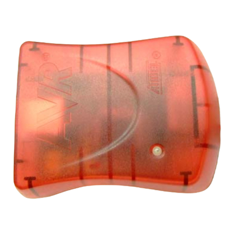
Atmel AVR943 User manual

Atmel

Atmel AVR943 User manual

Atmel STK520 User manual

Atmel

Atmel STK520 User manual
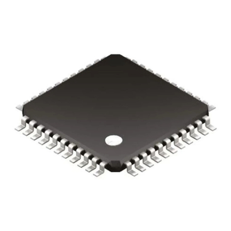
Atmel AVR XMEGA E Installation and operating instructions
Atmel

Atmel AVR XMEGA E Installation and operating instructions

Atmel AVR1921 Installation and operating instructions

Atmel

Atmel AVR1921 Installation and operating instructions

Atmel AT91CAP9A-DK User manual

Atmel

Atmel AT91CAP9A-DK User manual

Atmel AT90USB162 User manual

Atmel

Atmel AT90USB162 User manual
Atmel AT32UC3A3256S User manual

Atmel

Atmel AT32UC3A3256S User manual
Atmel AVR User manual

Atmel

Atmel AVR User manual
Atmel AT32UC3L064 User manual

Atmel

Atmel AT32UC3L064 User manual
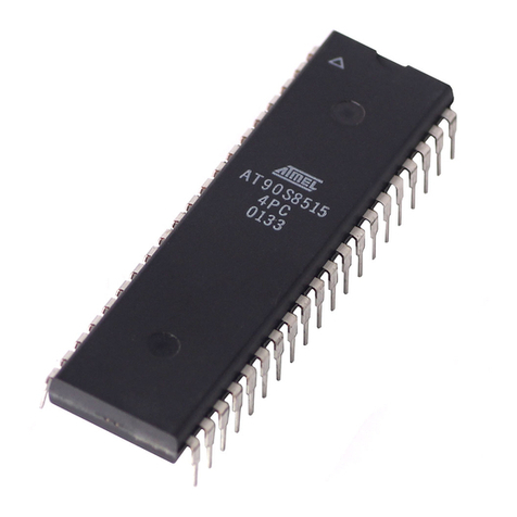
Atmel AT90S8515-8PI User manual

Atmel

Atmel AT90S8515-8PI User manual
Atmel AVR AVR350 Installation and operating instructions
Atmel

Atmel AVR AVR350 Installation and operating instructions

Atmel SAM L21 Xplained Pro User manual
Atmel

Atmel SAM L21 Xplained Pro User manual

Atmel SAM4L Xplained Pro User manual

Atmel

Atmel SAM4L Xplained Pro User manual
Atmel ATmega168PB Xplained Mini User manual
Atmel

Atmel ATmega168PB Xplained Mini User manual

Atmel AVR ATmega103 User manual

Atmel

Atmel AVR ATmega103 User manual

Atmel AVR180 Installation and operating instructions
Atmel

Atmel AVR180 Installation and operating instructions

Atmel ATmega128A-STK600 Installation and operating instructions

Atmel

Atmel ATmega128A-STK600 Installation and operating instructions

Atmel SAM L22G User manual

Atmel

Atmel SAM L22G User manual

Atmel XMEGA A3 series User manual

Atmel

Atmel XMEGA A3 series User manual

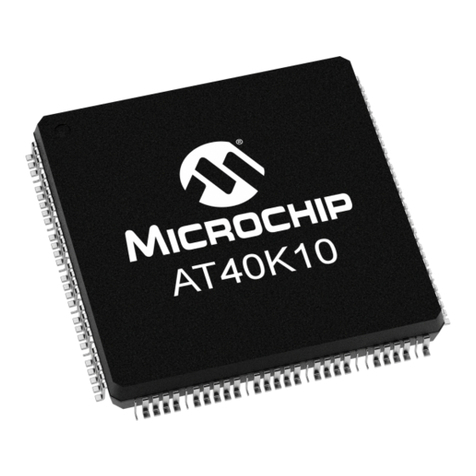
Atmel AT40K Installation and operating instructions

Atmel

Atmel AT40K Installation and operating instructions

Atmel AVR ATtiny22 Instruction Manual

Atmel

Atmel AVR ATtiny22 Instruction Manual

Popular Microcontroller manuals by other brands

Microsemi IGLOO nano Starter Kit user guide

Microsemi

Microsemi IGLOO nano Starter Kit user guide

GOWIN DK START GW1NSR-LV4CQN48PC7I6 V 1.1 user guide

GOWIN

GOWIN DK START GW1NSR-LV4CQN48PC7I6 V 1.1 user guide

HETRONIC ERGO-S Service manual

HETRONIC

HETRONIC ERGO-S Service manual

Laird BL654PA user guide

Laird

Laird BL654PA user guide

Novatek NT6861 manual

Novatek

Novatek NT6861 manual

Lantronix Intrinsyc Open-Q 865XR SOM user guide

Lantronix

Lantronix Intrinsyc Open-Q 865XR SOM user guide

Nuvoton ISD61S00 ChipCorder Design guide

Nuvoton

Nuvoton ISD61S00 ChipCorder Design guide

STMicrolectronics ST7 Assembler Linker user manual

STMicrolectronics

STMicrolectronics ST7 Assembler Linker user manual

Texas Instruments Chipcon CC2420DK user manual

Texas Instruments

Texas Instruments Chipcon CC2420DK user manual

NEC 78GK0S/K 1+ Series Application note

NEC

NEC 78GK0S/K 1+ Series Application note

Mikroe SEMITECH N-PLC Click Application note

Mikroe

Mikroe SEMITECH N-PLC Click Application note

Intel Agilex user guide

Intel

Intel Agilex user guide

DIGITAL-LOGIC MICROSPACE manual

DIGITAL-LOGIC

DIGITAL-LOGIC MICROSPACE manual

Texas Instruments TMS320F2837 D Series Workshop Guide and Lab Manual

Texas Instruments

Texas Instruments TMS320F2837 D Series Workshop Guide and Lab Manual

CYPRES CY14NVSRAMKIT-001 user guide

CYPRES

CYPRES CY14NVSRAMKIT-001 user guide

Espressif Systems ESP8266EX Programming guide

Espressif Systems

Espressif Systems ESP8266EX Programming guide

Abov AC33M8128L user manual

Abov

Abov AC33M8128L user manual

Silicon Laboratories C8051F800 user guide
Silicon Laboratories

Silicon Laboratories C8051F800 user guide
manuals.online logo
manuals.online logoBrands
  • About & Mission
  • Contact us
  • Privacy Policy
  • Terms and Conditions

Copyright 2025 Manuals.Online. All Rights Reserved.

1
Features
•Utilizes the AVR®RISC Architecture
•AVR – High-performance and Low-power RISC Architecture
– 118 Powerful Instructions – Most Single Clock Cycle Execution
– 32 x 8 General-purpose Working Registers
– Up to 10 MIPS Throughput at 10 MHz
•Data and Nonvolatile Program Memory
– 2K Bytes of In-System Programmable Flash
Endurance: 1,000 Write/Erase Cycles
– 128 Bytes Internal RAM
– 128 Bytes of In-System Programmable EEPROM
Endurance: 100,000 Write/Erase Cycles
– Programming Lock for Flash Program and EEPROM Data Security
•Peripheral Features
– One 8-bit Timer/Counter with Separate Prescaler
– Programmable Watchdog Timer with On-chip Oscillator
– SPI Serial Interface for In-System Programming
•Special Microcontroller Features
– Low-power Idle and Power-down Modes
– External and Internal Interrupt Sources
– Power-on Reset Circuit
– Selectable On-chip RC Oscillator
•Specifications
– Low-power, High-speed CMOS Process Technology
– Fully Static Operation
•Power Consumption at 4 MHz, 3V, 25°C
– Active: 2.4 mA
– Idle Mode: 0.5 mA
– Power-down Mode: <1 µA
•I/O and Packages
– Three Programmable I/O Lines for AT90S/LS2323
– Five Programmable I/O Lines for AT90S/LS2343
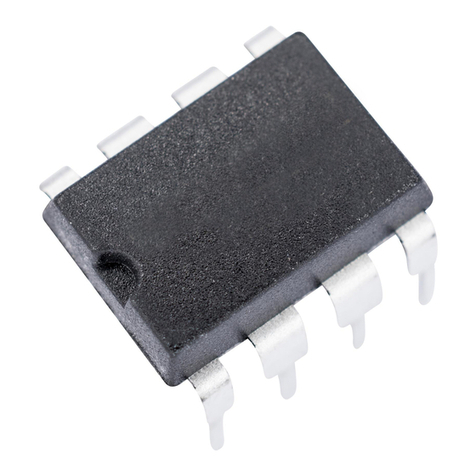
– 8-pin PDIP and SOIC
•Operating Voltages
– 4.0 - 6.0V for AT90S2323/AT90S2343
– 2.7 - 6.0V for AT90LS2323/AT90LS2343
•Speed Grades
– 0 - 10 MHz for AT90S2323/AT90S2343-10
– 0 - 4 MHz for AT90LS2323/AT90LS2343-4
– 0 - 1 MHz for AT90LS2343-1
Pin Configuration
PDIP/SOIC
1
2
3
4
8
7
6
5
RESET
XTAL1
XTAL2
GND
VCC
PB2 (SCK/T0)
PB1 (MISO/INT0)
PB0 (MOSI)
AT90S/LS2323
1
2
3
4
8
7
6
5
RESET
(CLOCK) PB3
PB4
GND
VCC
PB2 (SCK/T0)
PB1 (MISO/INT0)
PB0 (MOSI)
AT90S/LS2343
8-bit
Microcontroller
with 2K Bytes of
In-System
Programmable
Flash
AT90S2323
AT90LS2323
AT90S2343
AT90LS2343
Rev. 1004D–09/01
2AT90S/LS2323/2343
1004D–09/01
Description The AT90S/LS2323 and AT90S/LS2343 are low-power, CMOS, 8-bit microcontrollers
based on the AVR RISC architecture. By executing powerful instructions in a single
clock cycle, the AT90S2323/2343 achieves throughputs approaching 1 MIPS per MHz
allowing the system designer to optimize power consumption versus processing speed.
The AVR core combines a rich instruction set with 32 general-purpose working regis-
ters. All the 32 registers are directly connected to the Arithmetic Logic Unit (ALU),
allowing two independent registers to be accessed in one single instruction executed in
one clock cycle. The resulting architecture is more code efficient while achieving
throughputs up to ten times faster than conventional CISC microcontrollers.
Block Diagram Figure 1. The AT90S/LS2343 Block Diagram
PROGRAM
COUNTER
INTERNAL
OSCILLATOR
WATCHDOG
TIMER
STACK
POINTER
PROGRAM
FLASH
MCU CONTROL
REGISTER
SRAM
GENERAL
PURPOSE
REGISTERS
INSTRUCTION
REGISTER
TIMER/
COUNTER
INSTRUCTION
DECODER
DATA DIR.
REG. PORTB
DATA REGISTER
PORTB
PROGRAMMING
LOGIC
TIMING AND
CONTROL
INTERRUPT
UNIT
EEPROM
SPI
STATUS
REGISTER
Z
Y
X
ALU
PORTB DRIVERS
PB0 - PB4
RESET
VCC
GND
CONTROL
LINES
8-BIT DATA BUS
3
AT90S/LS2323/2343
1004D–09/01
Figure 2. The AT90S/LS2323 Block Diagram
The AT90S2323/2343 provides the following features: 2K bytes of In-System Program-
mable Flash, 128 bytes EEPROM, 128 bytes SRAM, 3 (AT90S/LS2323)/5
(AT90S/LS2343) general-purpose I/O lines, 32 general-purpose working registers, an 8-
bit timer/counter, internal and external interrupts, programmable Watchdog Timer with
internal oscillator, an SPI serial port for Flash Memory downloading and two software-
selectable power-saving modes. The Idle mode stops the CPU while allowing the
SRAM, timer/counters, SPI port and interrupt system to continue functioning. The
Power-down mode saves the register contents but freezes the oscillator, disabling all
other chip functions until the next interrupt or hardware reset.
The device is manufactured using Atmel’s high-density nonvolatile memory technology.
The On-chip Flash allows the program memory to be reprogrammed in-system through
an SPI serial interface. By combining an 8-bit RISC CPU with ISP Flash on a monolithic
PROGRAM
COUNTER
INTERNAL
OSCILLATOR
WATCHDOG
TIMER
STACK
POINTER
PROGRAM
FLASH
MCU CONTROL
REGISTER
SRAM
GENERAL
PURPOSE
REGISTERS
INSTRUCTION
REGISTER
TIMER/
COUNTER
INSTRUCTION
DECODER
DATA DIR.
REG. PORTB
DATA REGISTER
PORTB
PROGRAMMING
LOGIC
TIMING AND
CONTROL
OSCILLATOR
INTERRUPT
UNIT
EEPROM
SPI
STATUS
REGISTER
Z
Y
X
ALU
PORTB DRIVERS
PB0 - PB2
RESET
VCC
GND
CONTROL
LINES
8-BIT DATA BUS
4AT90S/LS2323/2343
1004D–09/01
chip, the Atmel AT90S2323/2343 is a powerful microcontroller that provides a highly
flexible and cost-effective solution to many embedded control applications.
The AT90S2323/2343 AVR is supported with a full suite of program and system devel-
opment tools including: C compilers, macro assemblers, program debugger/simulators,
in-circuit emulators and evaluation kits.
Comparison between
AT90S/LS2323 and
AT90S/LS2343
The AT90S/LS2323 is intended for use with external quartz crystal or ceramic resonator
as the clock source. The start-up time is fuse-selectable as either 1 ms (suitable for
ceramic resonator) or 16 ms (suitable for crystal). The device has three I/O pins.
The AT90S/LS2343 is intended for use with either an external clock source or the inter-
nal RC oscillator as clock source. The device has five I/O pins.
Table 1 summarizes the differences in features of the two devices.
Pin Descriptions
AT90S/LS2323
VCC Supply voltage pin.
GND Ground pin.
Port B (PB2..PB0) Port B is a 3-bit bi-directional I/O port with internal pull-up resistors. The Port B output
buffers can sink 20 mA. As inputs, Port B pins that are externally pulled low, will source
current if the pull-up resistors are activated.
Port B also serves the functions of various special features.
Port pins can provide internal pull-up resistors (selected for each bit). The Port B pins
are tri-stated when a reset condition becomes active.
RESET Reset input. An external reset is generated by a low level on the RESET pin. Reset
pulses longer than 50 ns will generate a reset, even if the clock is not running. Shorter
pulses are not guaranteed to generate a reset.
XTAL1 Input to the inverting oscillator amplifier and input to the internal clock operating circuit.
XTAL2 Output from the inverting oscillator amplifier.
Table 1. Feature Difference Summary
Part AT90S/LS2323 AT90S/LS2343
On-chip Oscillator Amplifier yes no
Internal RC Clock no yes
PB3 available as I/O pin never internal clock mode
PB4 available as I/O pin never always
Start-up time 1 ms/16 ms 16 µs fixed
5
AT90S/LS2323/2343
1004D–09/01
Pin Descriptions
AT90S/LS2343
VCC Supply voltage pin.
GND Ground pin.
Port B (PB4..PB0) Port B is a 5-bit bi-directional I/O port with internal pull-up resistors. The Port B output
buffers can sink 20 mA. As inputs, Port B pins that are externally pulled low, will source
current if the pull-up resistors are activated.
Port B also serves the functions of various special features.
Port pins can provide internal pull-up resistors (selected for each bit). The Port B pins
are tri-stated when a reset condition becomes active.
RESET Reset input. An external reset is generated by a low level on the RESET pin. Reset
pulses longer than 50 ns will generate a reset, even if the clock is not running. Shorter
pulses are not guaranteed to generate a reset.
CLOCK Clock signal input in external clock mode.
Clock Options
Crystal Oscillator The AT90S/LS2323 contains an inverting amplifier that can be configured for use as an
On-chip oscillator, as shown in Figure 3. XTAL1 and XTAL2 are input and output
respectively. Either a quartz crystal or a ceramic resonator may be used. It is recom-
mended that the AT90S/LS2343 be used if an external clock source is used, since this
gives an extra I/O pin.
Figure 3. Oscillator Connection
External Clock The AT90S/LS2343 can be clocked by an external clock signal, as shown in Figure 4, or
by the On-chip RC oscillator. This RC oscillator runs at a nominal frequency of 1 MHz
(VCC = 5V). A fuse bit (RCEN) in the Flash memory selects the On-chip RC oscillator as
the clock source when programmed (“0”). The AT90S/LS2343 is shipped with this bit
programmed. The AT90S/LS2343 is recommended if an external clock source is used,
because this gives an extra I/O pin.
The AT90S/LS2323 can be clocked by an external clock as well, as shown in Figure 4.
No fuse bit selects the clock source for AT90S/LS2323.
6AT90S/LS2323/2343
1004D–09/01
Figure 4. External Clock Drive Configuration
GND
GND
EXTERNAL
OSCILATOR
SIGNAL
EXTERNAL
OSCILATOR
SIGNAL
NC XTAL2
XTAL1
PB3
AT90S/LS2323AT90S/LS2343
7
AT90S/LS2323/2343
1004D–09/01
Architectural
Overview
The fast-access register file concept contains 32 x 8-bit general-purpose working regis-
ters with a single clock cycle access time. This means that during one single clock cycle,
one ALU (Arithmetic Logic Unit) operation is executed. Two operands are output from
the register file, the operation is executed and the result is stored back in the register file
–in one clock cycle.
Six of the 32 registers can be used as three 16-bit indirect address register pointers for
Data Space addressing, enabling efficient address calculations. One of the three
address pointers is also used as the address pointer for the constant table look-up func-
tion. These added function registers are the 16-bit X-, Y-, and Z-register.
Figure 5. The AT90S2323/2343 AVR RISC Architecture
The ALU supports arithmetic and logic functions between registers or between a con-
stant and a register. Single register operations are also executed in the ALU. Figure 5
shows the AT90S2323/2343 AVR RISC microcontroller architecture.
In addition to the register operation, the conventional memory addressing modes can be
used on the register file as well. This is enabled by the fact that the register file is
assigned the 32 lowermost Data Space addresses ($00 - $1F), allowing them to be
accessed as though they were ordinary memory locations.
The I/O memory space contains 64 addresses for CPU peripheral functions such as
Control Registers, Timer/Counters, A/D converters and other I/O functions. The I/O
memory can be accessed directly or as the Data Space locations following those of the
register file, $20 - $5F.
1K x 16
Program
Flash
Instruction
Register
Instruction
Decoder
Program
Counter
Control Lines
32 x 8
General
Purpose
Registers
ALU
Status
and Test
Control
Registers
Interrupt
Unit
SPI
Unit
8-bit
Timer/Counter
Watchdog
Timer
I/O Lines
128 x 8
EEPROM
Data Bus 8-bit
128 x 8
Data
SRAM
Direct Addressing
Indirect Addressing
8AT90S/LS2323/2343
1004D–09/01
The AVR has Harvard architecture –with separate memories and buses for program
and data. The program memory is accessed with a two-stage pipeline. While one
instruction is being executed, the next instruction is pre-fetched from the program mem-
ory. This concept enables instructions to be executed in every clock cycle. The program
memory is in-system downloadable Flash memory.
With the relative jump and call instructions, the whole 1K address space is directly
accessed. Most AVR instructions have a single 16-bit word format. Every program
memory address contains a 16- or 32-bit instruction.
During interrupts and subroutine calls, the return address Program Counter (PC) is
stored on the stack. The stack is effectively allocated in the general data SRAM and
consequently, the stack size is only limited by the total SRAM size and the usage of the
SRAM. All user programs must initialize the SP in the reset routine (before subroutines
or interrupts are executed). The 8-bit stack pointer (SP) is read/write-accessible in the
I/O space.
The 128 bytes data SRAM + register file and I/O registers can be easily accessed
through the five different addressing modes supported in the AVR architecture.
The memory spaces in the AVR architecture are all linear and regular memory maps.
Figure 6. Memory Maps
A flexible interrupt module has its control registers in the I/O space with an additional
global interrupt enable bit in the status register. All the different interrupts have a sepa-
rate interrupt vector in the interrupt vector table at the beginning of the program
memory. The different interrupts have priority in accordance with their interrupt vector
position. The lower the interrupt vector address, the higher the priority.
EEPROM
(128 x 8)
$000
$07F
EEPROM Data Memory
9
AT90S/LS2323/2343
1004D–09/01
General-purpose
Register File
Figure 7 shows the structure of the 32 general-purpose registers in the CPU.
Figure 7. AVR CPU General-purpose Working Registers
All the register operating instructions in the instruction set have direct and single-cycle
access to all registers. The only exception is the five constant arithmetic and logic
instructions SBCI, SUBI, CPI, ANDI and ORI between a constant and a register and the
LDI instruction for load immediate constant data. These instructions apply to the second
half of the registers in the register file (R16..R31). The general SBC, SUB, CP, AND and
OR and all other operations between two registers or on a single register apply to the
entire register file.
As shown in Figure 7, each register is also assigned a data memory address, mapping
them directly into the first 32 locations of the user Data Space. Although the register file
is not physically implemented as SRAM locations, this memory organization provides
great flexibility in access of the registers, as the X-, Y-, and Z-registers can be set to
index any register in the file.
70Addr.
R0 $00
R1 $01
R2 $02
…
R13 $0D
General R14 $0E
Purpose R15 $0F
Working R16 $10
Registers R17 $11
…
R26 $1A X-register low byte
R27 $1B X-register high byte
R28 $1C Y-register low byte
R29 $1D Y-register high byte
R30 $1E Z-register low byte
R31 $1F Z-register high byte
10 AT90S/LS2323/2343
1004D–09/01
X-register, Y-register and Z-
register
The registers R26..R31 have some added functions to their general-purpose usage.
These registers are the address pointers for indirect addressing of the Data Space. The
three indirect address registers X, Y, and Z, are defined in Figure 8.
Figure 8. The X-, Y-, and Z-registers
In the different addressing modes, these address registers have functions as fixed dis-
placement, automatic increment and decrement (see the descriptions for the different
instructions).
ALU –Arithmetic Logic
Unit
The high-performance AVR ALU operates in direct connection with all the 32 general-
purpose working registers. Within a single clock cycle, ALU operations between regis-
ters in the register file are executed. The ALU operations are divided into three main
categories: arithmetic, logic and bit functions.
In-System
Programmable Flash
Program Memory
The AT90S2323/2343 contains 2K bytes On-chip, In-System Programmable Flash
memory for program storage. Since all instructions are 16- or 32-bit words, the Flash is
organized as 1K x 16. The Flash memory has an endurance of at least 1000 write/erase
cycles.
The AT90S2323/2343 Program Counter (PC) is 10 bits wide, hence addressing the
1024 program memory addresses. See page 42 for a detailed description on Flash data
programming.
Constant tables must be allocated within the address 0 - 2K (see the LPM –Load Pro-
gram Memory instruction description on page 60).
See page 12 for the different addressing modes.
EEPROM Data Memory The AT90S2323/2343 contains 128 bytes of EEPROM data memory. It is organized as
a separate data space, in which single bytes can be read and written. The EEPROM has
an endurance of at least 100,000 write/erase cycles. The access between the EEPROM
and the CPU is described on page 32, specifying the EEPROM address register, the
EEPROM data register and the EEPROM control register.
For the SPI data downloading, see page 42 for a detailed description.
15 0
X-register 7 0 7 0
R27 ($1B) R26 ($1A)
15 0
Y-register 7 0 7 0
R29 ($1D) R28 ($1C)
15 0
Z-register 7 0 7 0
R31 ($1F) R30 ($1E)