Atmos Atmoforte 350 User manual

1
Atmoforte 350
Record 500
444.0350.B DF.01
Operating instructions
0124
MedizinTechnik

2
General Information
•The product Atmoforte 350/Record 500 bears the CE
mark CE-0124 in accordance with the Council
Directive 93/42/EEC about medical devices and fulfills
the essential requirements of Annex I of this directive.
•The product fully complies with the electromagnetic
immunity requirements of standard EN 60601-1-2
"Electromagnetic Compatibility - Medical Electrical
Equipment".
•These operating instructions are an integral part of
the device. They should always be kept near the
device. Close observance of these instructions is a
prerequisite for applying the device according to its
intended use and for correct operation.
•Patient safety and interference-free operation can be
guaranteed only if original ATMOS parts are used.
Furthermore only the accessories listed in this manual
are approved by ATMOS and may be used in
conjunction with the device, or else accessories whose
use has been expressly permitted by ATMOS. In the
event that other accessories or consumables are used,
ATMOS does not guarantee the safe operation and
reliable performance of the device.
•ATMOS cannot be held liable for any damages
resulting from the use of accessories or consumables
from other manufacturers.
•Atmoforte 350 and Record 500 differ only with regard
to pumps, air-flow rates and final vacuum. Operation
and design of the units are identical. In following
sections, the name Atmoforte 350/Record 500 is,
therefore, used.
•ATMOS considers itself responsible for safety,
reliability and perfomance of the device only
– if assembly, readjustment, modification, extension,
or repair is carried out by ATMOS or by persons
authorized by ATMOS
– if the device is used in compliance with these
operating instructions.
• ATMOS supplies a service manual containing detailed
circuit descriptions and schematics as well as
information on adjustment and servicing to the
authorized service staff.
• These operating instructions are in conformity with
the device specifications and publications on safety
of medical electrical equipment valid at printing date.
All rights are reserved for circuits, techniques, names,
software programs and devices mentioned in this
manual.
• The ATMOS quality management system fully
complies with the international standards DIN EN ISO
9001 and EN 46001.
• No part of this manual may be reproduced without
written permisssion from ATMOS.
ATMOS
MedizinTechnik GmbH & Co. KG
Ludwig-Kegel-Straße 16
79853 Lenzkirch
Deutschland / Germany
Tel. + 49 (0) 76 53 / 6 89-0
Fax: + 49 (0) 76 53 / 6 89-190
+ 49 (0) 76 53 / 6 89-393 (Service Center)
e-mail: [email protected]
Internet: http://www.atmosmed.de

3
Contents Page
1. Application and Functional Description
1.1 Intended Use ........................................................................... 4
1.2 Function ................................................................................... 5
1.3 Safety information .................................................................... 6
2. Operating Controls and Indicators ........................................ 7 - 8
3. First-Time Operation ............................................................. 9 - 12
4. Operation .............................................................................. 14 - 19
4.1 General points to note during Operation ............................... 14
4.2 Suction Mode (Standard Mode) ..................................... 15 - 16
4.3 Suction Mode (Low Vacauum Range) ........................... 17 - 18
4.4 Vacuum Extraction ................................................................. 19
5. Cleaning and Maintenance ................................................. 20 - 22
6. Trouble-shooting ................................................................. 23 - 24
7. Spare Parts and Accessories ............................................. 25 - 27
7.1 Spare Parts .................................................................... 25 - 26
7.2 Accessories and Supplies ..................................................... 27
8. Technical Specifications ............................................................. 28
General Standard Terms and Conditions
4
1. Application and Functional
Description
1.1 Intended Use
The Atmoforte 350/Record 500 is a compact suction unit
for medical application. It is especially intended for
aspiration and collection of secretions, body fluids and
tissue. Its main fields of application are:
–in the OPD, in the OR: during surgery, e.g. to drain
pockets or abscesses
–in endoscopy: e.g. to aspirate secretions or rinsing
solutions
–in gynaecology: for suction curettage and vacuum
extraction (obstetrics)
–in ENT applications: to aspirate secretions, rinsing
solutions, cerumen
–in the recovery ward and ICU: for the spontaneous
aspiration of body fluids, e.g. from the respiratory tract
– for drainage in the low vacuum range (e.g. thorax
drainage)
The Atmoforte 350/Record 500 must not be used :
– in non-medical applications
– to aspirate flammable or explosive fluids or gases.
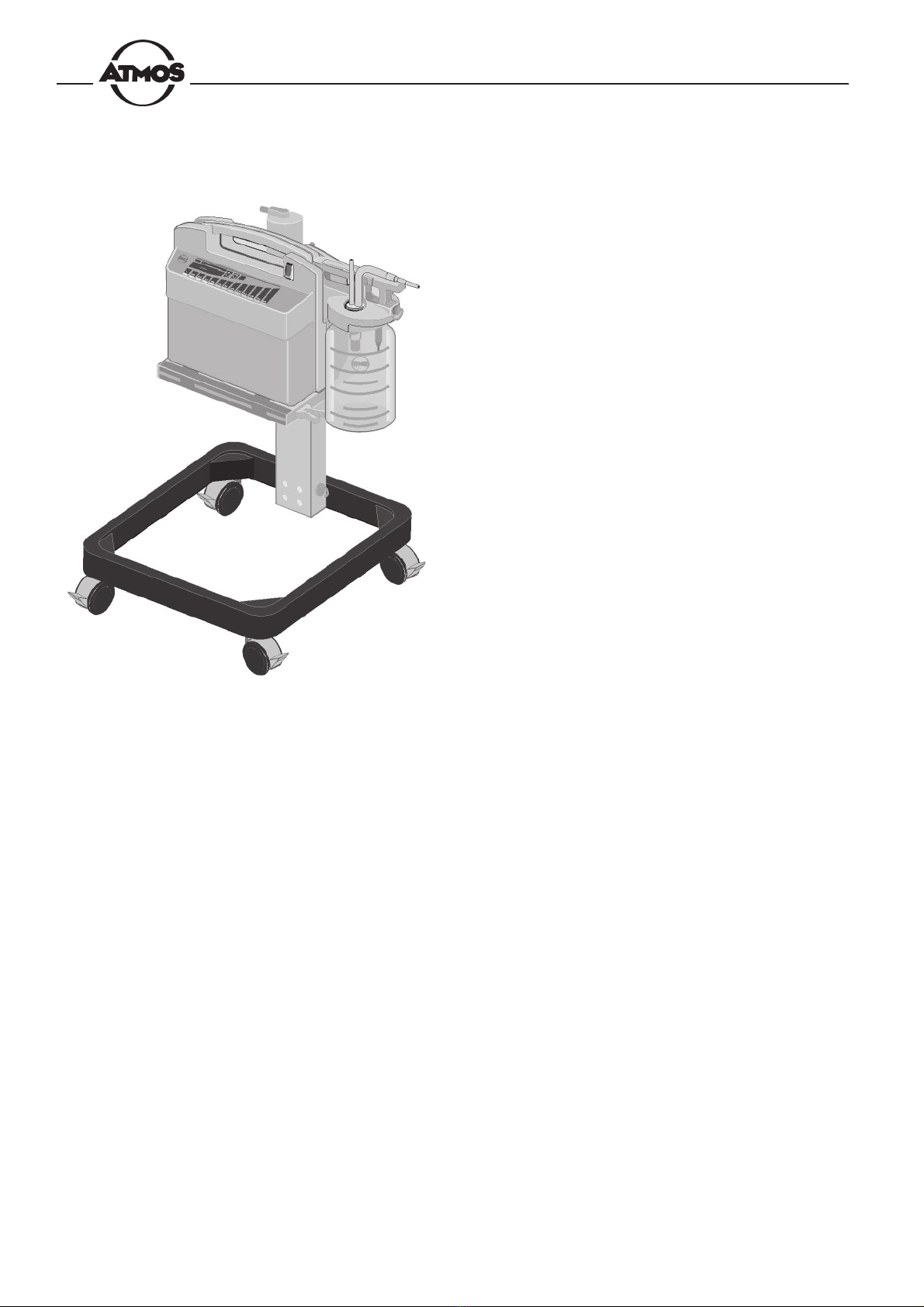
Fig.1. Atmoforte 350 (with optional trolley)
Record 500 (trolley included in standard
equipment of user packages)

5
Secretions must not be allowed to enter the pump.
If this happens in spite of fill-level monitoring and
overflow protection (fluid trap), the Atmoforte 350/
Record 500 must be inspected by a service technical
before being used again on a patient.
The suction tube must never come into direct
contact with the application site. A suction catheter,
suction tip or medical aspiration set must always be
connected to the tube.
Excessive vacuum settings may cause lesions
in the tissue.
1.2 Function
The Atmoforte 350/Record 500 is a line-power operated
suction unit, centering around a silent, maintenance-free
diaphragm pump which produces a vacuum inside the
collection jar for aspiration and collection of the secretions.
The target vacuum is key-selectable in 12 steps. The
vacuum build-up is microprocessor-controlled. When the
target vacuum has been reached, the pump switches off. A
closed-loop control circuit activates the pump only when
needed to re-establish the selected vacuum setting.
Electronic fill-level monitoring and a fluid trap with
integrated bacterial filter are implemented to prevent that
secretions enter the pump. The filter can be cleaned and
sterilized.
Several monitoring and control functions enhance the
operational ease of the Atmoforte 350/Record 500 and
ensure its safe application. Among these are:
– electronic monitoring of the collection jar fill level: the
unit emits audio and visual signals when the max. fill
level is exceeded
– automatic standby: when idling, the pump automatically
switches to standby (e.g. while the suction cannula is
removed from the application site) and resumes when
the cannula is in contact again with the substance to
be aspirated
– electronic filter monitoring: the unit emits audio and
visual signals when the filter is clogged
– automatic mode for vacuum extraction: the required
vacuum builds up gradually and is reached within about
2 minutes
– automatic clog detection: interrupts the suction
operation when the cannula adheres to the tissue
– regular, automatic performance tests: if malfunctions
are detected, the corresponding pilot lamp lights up.
All parts of the system which come into contact with the
secretions (tubes, collection jar, cover and lids) can be
autoclaved (up to 136°C).
A special equipment trolley can be ordered for mobile
application of the Atmoforte 350 (Fig. 1).
User packages of the Record500 are standardly equipped
with this trolley.

6
1.3 For your Safety
•Dispose of the packaging material, observing the
applicable waste-control regulations.
•The design of the Atmoforte 350/Record 500 fulfills
the requirements of IEC 601/EN 60601 and of
Protection class I. The device must be connected to a
properly installed socket with a non-fused earthed wire.
•Before connecting the device to the power line, check
that the line voltage and frequency are identical with
the ratings specified on the nameplate.
•The use of extension cords with multiple power outlets
is not permitted.
•Before putting the device into operation, visually check
all connection cables and tubes for signs of damage.
Damaged cables and tubes must be replaced
immediately.
•When disconnecting the device from the power line,
first remove the plug from the wall outlet. Then the
power cord may be disconnected from the device.
Never touch the plug or cord while your hands are
wet.
•The ambient conditions indicated in the Technical
Specifications must be strictly observed.
•The air vents on the underside of the device must not
be obstructed (do not place the device on soft
materials).
•Set up the device so that the operator has a clear,
unobstructed view of and easy access to the front
panel.
•The Atmoforte 350/Record 500 is not suitable for
operation in areas of medically used rooms where an
explosion hazard may occur. Explosion hazards may
result from the use of flammable anesthetics, skin
cleaning agents or disinfectants. Installed on the trolley,
the Atmoforte350/Record500is automatically placed
outside the area where an explosion hazard may
occur (refer to the literature list at the end of this
section).
•Install the Atmoforte350/Record500only on vibration-
free surfaces.
•The suction tube must never come into direct contact
with the application site. A suction catheter, suction
tip or medical aspiration set must always be connected
to the tube.
•Liquids must not be allowed to enter the device. Should
liquids have penetrated into the device, it must be
inspected by a service technician before being used
again.
•Before applying the device, the user is obligated to
check it for functional safety and proper performance.
•The user must be familiar with the operation of the
device.
•Information which is of particular interest to the user
is printed in a box throughout this manual.
ATMOS cannot be held liable for injury to persons
or damage to property if
– the parts used are not origin ATMOS parts
– the user instructions given in this manual are
disregarded.
Literature
Medical Device Directive
IEC 601-1/EN60601-1/1990: Medical electrical equipment.
General requirements for safety; section 6: Protection
against hazards of ignition of flammable anesthetic
mixtures
7
2. Operating Controls and Indicators
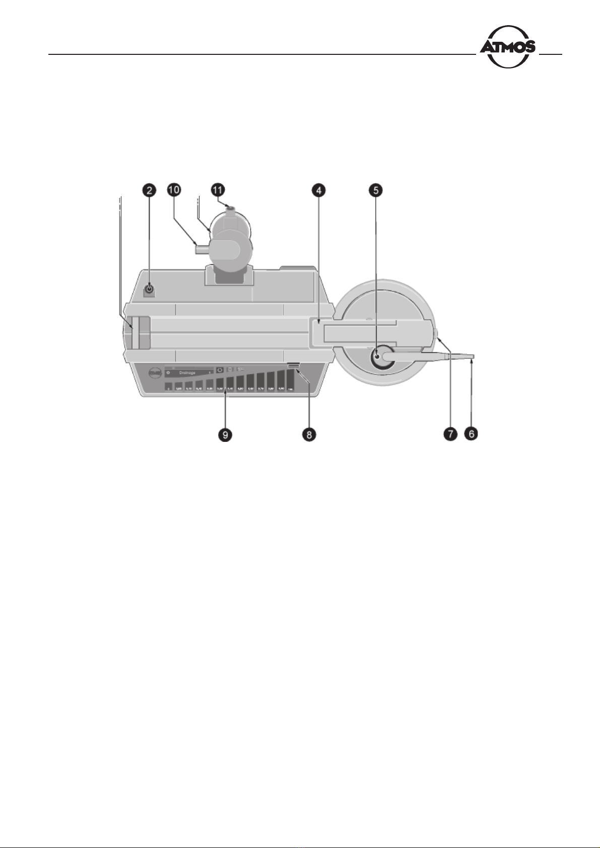
Fig. 2. Atmoforte 350/Record 500
nFixation and contact element for collection jar
oConnection piece for suction pump
pFluid trap with filter
qFixation for collection jar
rConnection piece for tube connecting the fluid trap
sConnection piece for suction tube
tLid system release button (for lid of collection jar)
uPower switch
vDisplay and control panel
wFilter output (to pump connection piece)
zFilter input (from collection jar)
11
p
n

8
Fig. 3. Atmoforte 350/Record 500 (rear view)
zPower input
zFuses
zPotential equalization pin
zPedal regulator port
12
13
14
15
Automatic standby on/off
"Clogged filter"/Max. fill level exceeded"
Malfunction indicator
Explanation of Symbols as Used on the Unit
Caution: Refer to operating instructions
Instrument fuse
Device off
Device on
9
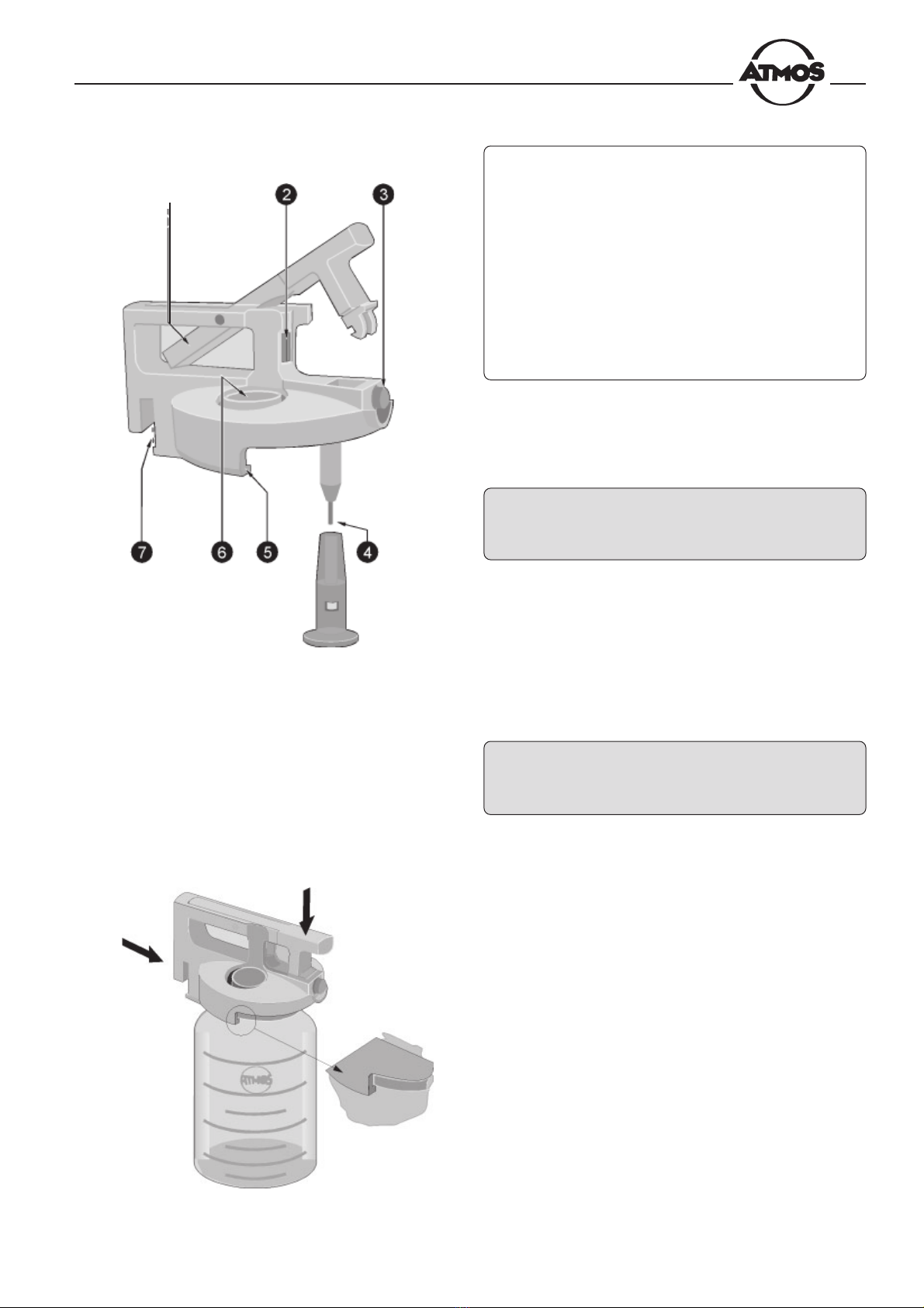
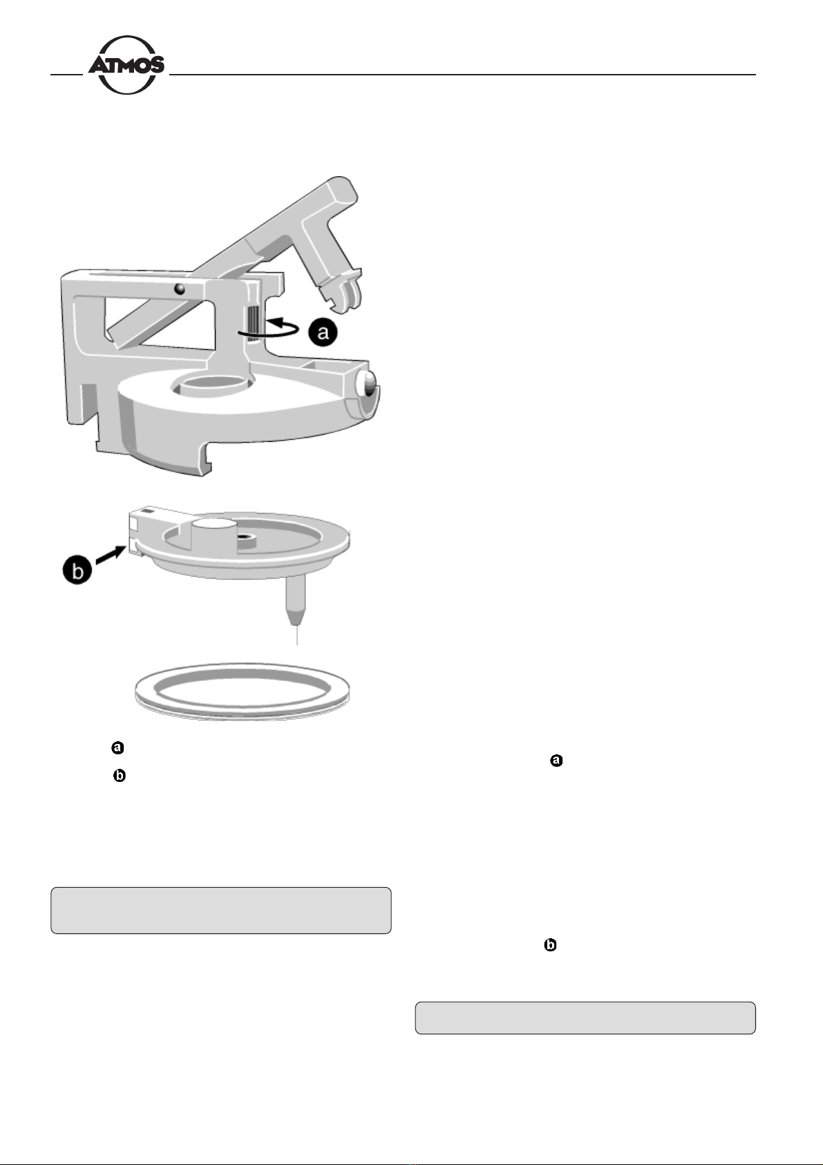
Fig. 5. Mounting the lid
Fig. 4. Lid system
nLocking bow
oKnurled screw for removal of the lid insert
pRelease knob
qFill-level sensor with foam protection
rLid rim
sAperture for double socket nipple
tContacts for monitoring of the fill level
– how to handle the lid system of the collection jar
– how to close and insert the collection jar
– how and where to connect the tubes
– how to connect the Atmoforte 350/Record 500 to
the power line
Before putting the device into operation for the
first time, do not fail to read section 1.3 "For your
Safety".
The lid system must seal the collection jar tight to allow
the vacuum to build up inside. Fig. 4 shows the lid system
with the locking bow open.
* Slide the lid system onto the collection jar as shown in
Fig. 5, taking care that the rim of the lid (r, Fig. 4) is
placed below the rim of the jar, and press down the
locking bow until you hear it click into place.
n
3. First-Time Operation
When dealing with heavily foaming secretions,
the foam protector should be attached to the fill-level
sensor.
This section decribes
10
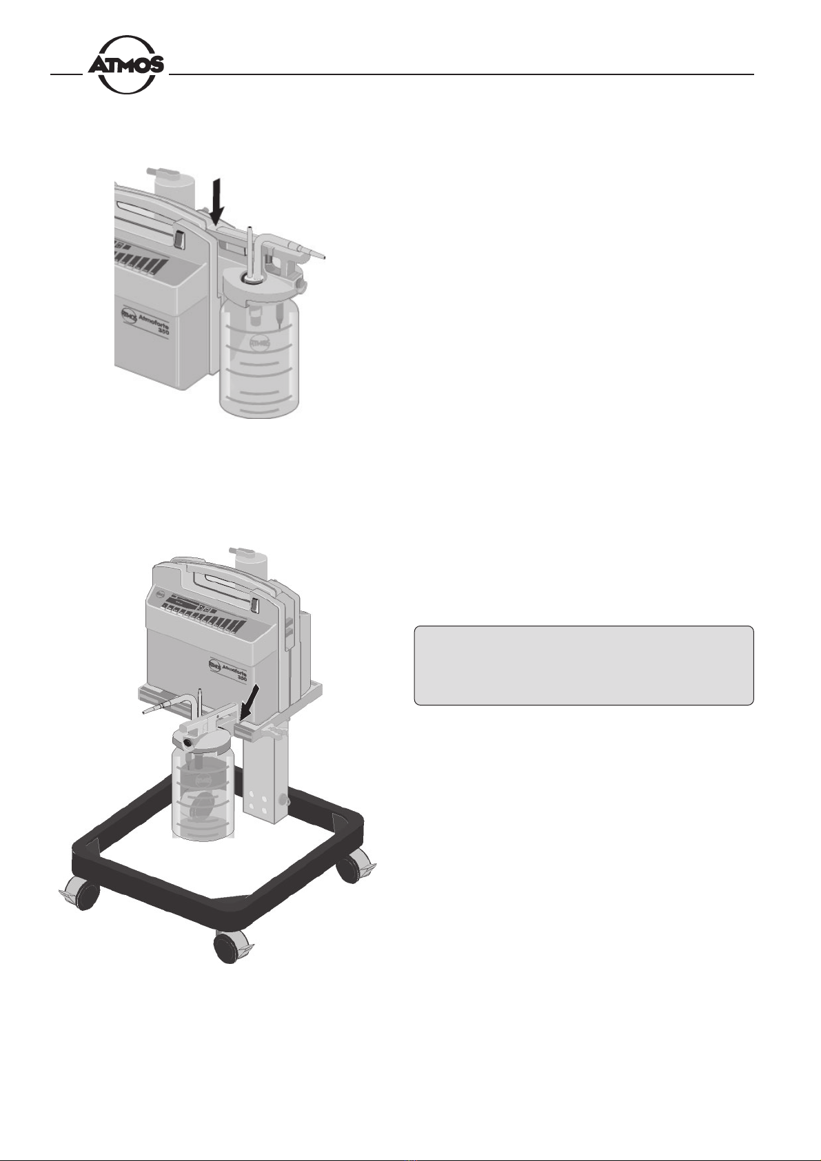
Fig. 6. Suspending the collection jar
Fig. 7. 3 or 5-liter jar suspended on the trolley
• Suspend the collection jar in the fixture on the right or
left side of the device as shown in Fig. 6.
3 or 5-liter jars are suspended on the trolley as per Fig. 7.
When placed on the trolley, the Atmoforte 350/
Record 500 must be firmly secured to the trolley
storage tray by means of the two screws (underside
of the tray) to ensure good contact for monitoring of
the fill level.

11
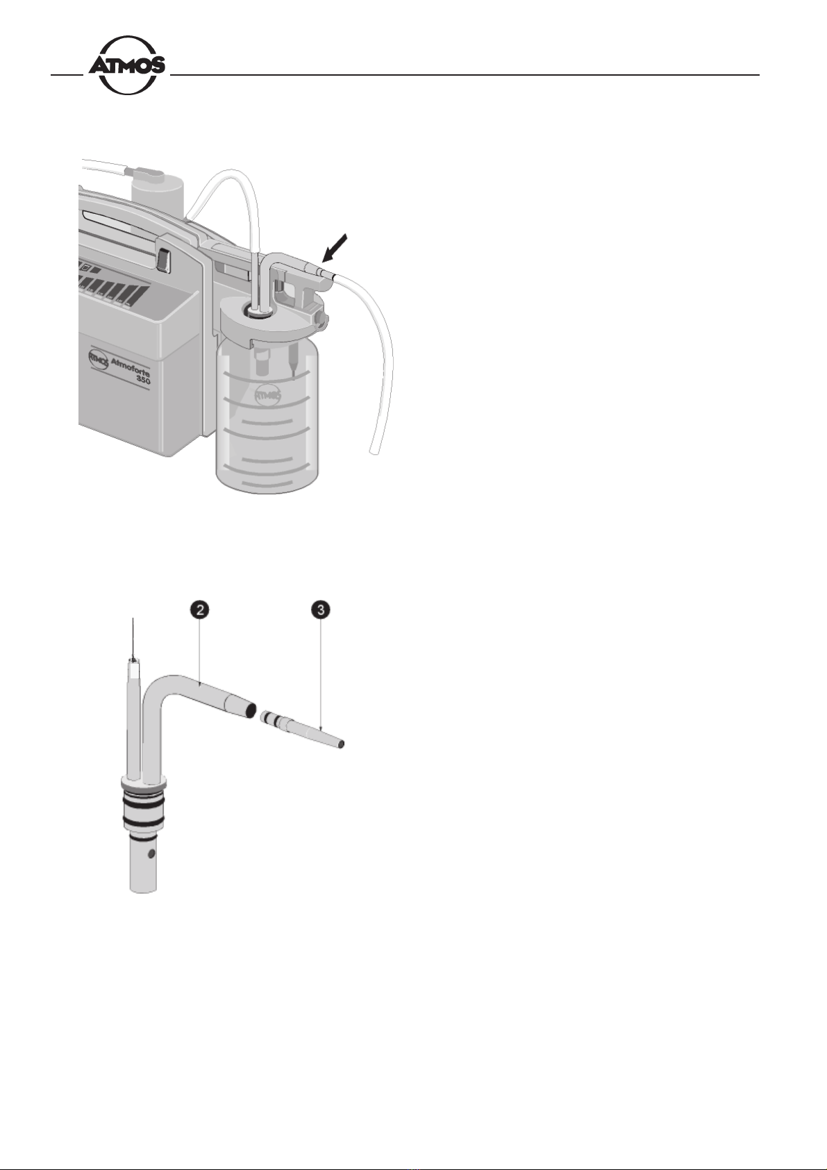
Fig. 8. Inserting the double socket nipple
Fig. 9. Connection tubes
• Insert the double socket nipple in the lid (Fig. 8). It is
important that you hear it lock into place.
• Use the short piece of tubing to connect the pump
connection piece nto the nipple of the filter oand,
the long tube to connect the vertical connection piece
of the double socket nipple qto the nipple of the fluid
trap p.
n
12
• Slide the suction tube onto the horizontal connection
piece to the double socket nipple.
Fig. 11. Double socket nipple
nConnection piece for fluid trap tube
oConnection piece for suction tube
pAdapter for 6-mm tube
Fig. 10. Connecting the suction tube
n
Connect the 10-mm suction tube directly to the connection
piece o. For the thin 6-mm tube you will have to add the
tube adapter p.

13
• Check that the power ratings marked on the device are
identical with those of your local power line. Then
connect the Atmoforte 350/Record 500 on the power
line (power input w).
* If you have purchased the optional pedal regulator,
connect it to port .
The Atmoforte350/Record500 is now ready for operation.
Fig. 12. Atmoforte 350/Record 500 Rear view.
wPower input
Potential equalization pin
Pedal regulator port
w
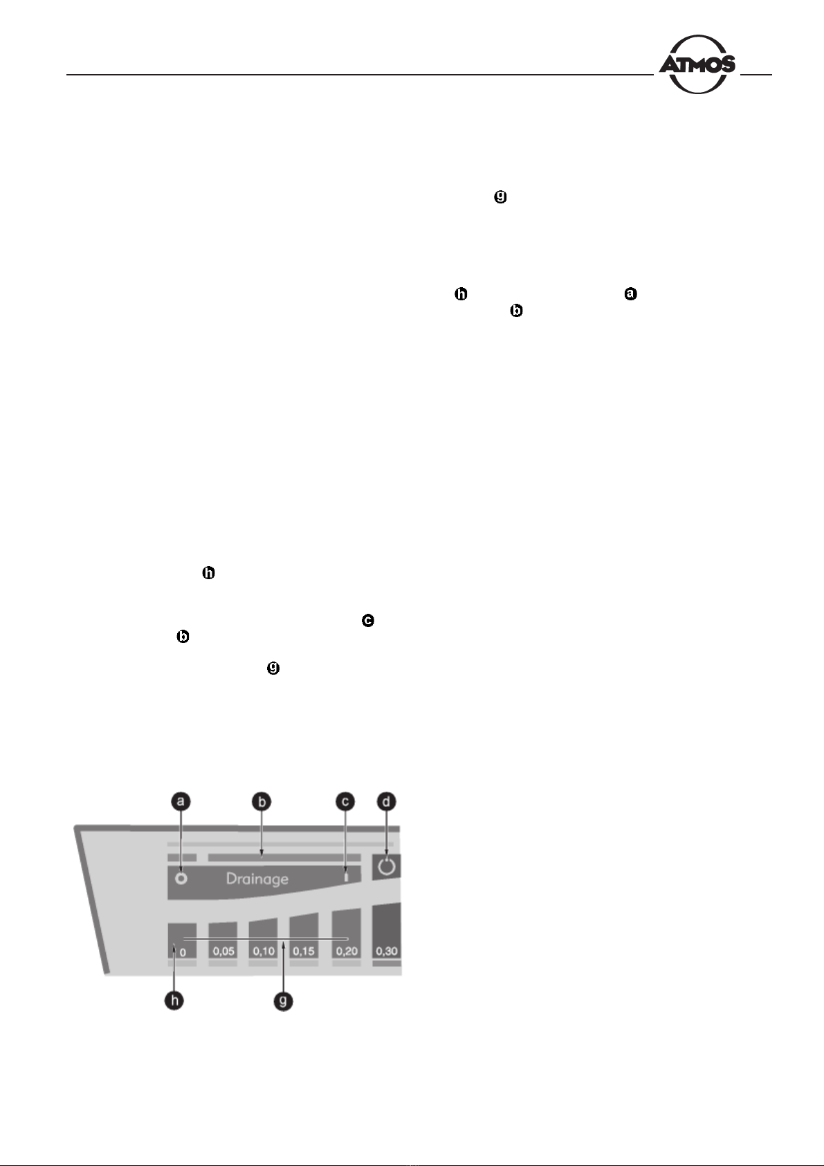
Fig. 13. Display and control panel
Turns off the fine-control suction or
longterm drainage mode
Bar indicator (yellow during drainage
application
Turns on the fine-control suction or
longterm drainage mode
Enables/disables the automatic
fstandby function (inoperative when the
pedal regulator is connected.
Lights up when filter is clogged - blinks
when max. fill level has been reached
Malfunction indicator
Dual function controls: selection of the
target vacuum - indication of the actual
vacuum (in bars)
For OR applications, we recommend to connect
the Atmoforte 350/Record 500 to the room´s potential
equalization system via pin (Fig. 12).

14
4. Operation
Fig.14. Lid system with fill-level sensor
The bacterial filter can be used up to about 200
times. It can be cleaned and sterilized. The filter is
electronically monitored for clogging. The inserted
filters must be completely dry.
The suction tube must never come into direct
contact with the application site. A suction catheter,
suction tip or medical aspiration set must always be
connected to the tube.
q
In this section you will find detailed information on
– how the automatic standby function as well as the
electronic fill-level and filter monitoring work
– how to operate the Atmoforte 350/Record 500 as
a suction unit (normal range, low vacuum range)
and how to replace and empty the collection jar
– how to perform long-term drainage with the water
vacuum gauge
– how to perform vacuum extraction
Before using the device on a new patient, make
sure that the following parts have been sterilized:
– the suction tube incl. the suction tip or aspiration
set
– the collection jar incl. lid and double socket nipple
– the connection tube to the fluid trap as well as the
fluid trap and the bacterial filter.
4.1 General Points to note during
Operation
Automatic Standby Function
With the automatic standby function enabled, the
Atmoforte 350/Record 500 will automatically switch to the
standby mode when left idle for about 12 seconds (e.g.
open suction tip). As soon as the suction tip is reimmersed
in the substance to be aspirated, the pump restarts at full
capacity. This method prevents unnecessary noise.
However, for some special applications, e.g. when using
extremely narrow suction cannulae, suction tubes with pool
suction tips or disposable suction bags with filter stones,
the automatic standby function may have to be disabled.
The function is switched on and off with the key ( ),
Fig. 13) . The key is lit when the function is enabled.
Electoronic Fill-Level Monitoring
The Atmoforte350/Record500 electronically monitors the
fill level in the collection jar. When the max. fill level is
reached, i.e., when the fluid level reaches the sensor (q,
Fig. 14) the pump switches off, 5 short audio signals sound
and the indicator ( , Fig. 13) starts blinking. When
the aspired substance creates large amounts of foam,
we recommend to add the foam protection to prevent that
the pump shuts off prematurely. As soon as the sensor is
no longer in contact with the liquid (e.g. after inserting the
double socket nipple in the second collection jar, if
present), the pump restarts.

15
Fig. 15. Turning on the Atmoforte 350/Record 500
4.2 Suction Mode (Standard Mode)
• Connect the suction catheter, the suction tip or the
suction set to the pump.
• Turn on the Atmoforte 350/Record 500: the indicator
in the power switch must light up!
• Push one of keys , Fig. 16, to select the desired target
vacuum (the vacuum is given in bar).
The Atmoforte350/Record500starts up and begins to build
up the vacuum. As the vacuum increases, the indicators
corresponding to the vacuum attained light up one after
the other. When the selected vacuum has been reached,
the pump switches off. During operation of the Atmoforte
350/Record500, a control circuit monitors the vacuum and
activates the pump only when needed to reestablish the
selected vacuum setting.
While at work, keep an eye on the fill level in the collection
jar. Even though the electronic fill-level sensor switches
off the pump when the max. fill level has been reached,
the jar should be exchanged or emptied at 2/3 of its max.
fill level (incl. foam) (Fig. 17).
If, in spite of fill-level monitoring and overflow
protection (fluid trap), secretions have entered the
pump, the Atmoforte 350/Record 500 must be
inspected by a service technician before being used
again on a patient.
Fig. 16. Display and control panel
Turns off the fine-control suction or
longterm drainage mode
Bar indicator (yellow during drainage
application
Turns on the fine-control suction or
longterm drainage mode
Enables/disables the automatic
fstandby function
Lights up when filter is clogged - blinks
when max. fill level has been reached
Malfunction indicator
Dual function controls: selection of the
target vacuum - indication of the actual
vacuum (in bars)

16
Fig. 18. Removing the double socket nipple
Fig. 19. Removing the collection jar
Fig. 17. Recommended max. fill level
Exchanging the Collection Jar
• Interrupt the procedure and switch off the pump.
• Remove the double socket nipple from the jar (Fig.
18). If a second collection jar has been installed, insert
the double socket nipple there.
• The jar is easy to remove if you tilt it a little away from
the device and then lift it off (Fig. 19).
• Either insert a new jar or empty the one that you just
removed. Press the release button to open the locking
bow (Fig. 18). Dispose of the contents of the collection
jar, observing the applicable waste control regulations.
• Insert the double socket nipple in the empty jar and
continue the procedure.
After Use
• At the end of the procedure, switch off the Atmoforte
350/Record 500 and clean the device and the
accessories as desribed in section 5 "Cleaning and
Maintenance".
17
4.3 Suction Mode (Low Vacuum Range)
For applications requiring a low vacuum, you can choose
between two operating modes.
–fine-control suction, a method which protects
delicate tissue by combining a low vacuum (-0,2 bar
max.) with optimal suction capacity
–long-term drainage with the optional water vacuum
gauge, e.g. for thorax drainage.
Fine-Control Suction
The fine-control suction mode, at settings between 0.05
and -0,2 bar, is ideal for applications involving delicate
tissue. In this mode the automatic clog detection briefly
suspends system operation when the suction tip adheres
to the tissue. The suction process continues when the
cannula has been disengaged from the tissue.
• Connect the suction catheter, the suction tip or the
suction set.
• Turn on the Atmoforte 350/Record 500: the power
switch must light up!
• Press the "0" key to enable selection of the fine-
control suction mode ("drainage" displays).
• Activate the fine-control suction mode with . The
bar indicator lights up yellow.
• Push one of the yellow keys to select the desired
target vacuum.
Fig. 20. Dispaly and control panel
The Atmoforte 350/Record 500 starts up and begins to
build up the vacuum. As the vacuum increases, the
indicators corresponding to the vacuum attained light
up one after the other. Whenever the suction cannula
adheres to the tissue, the pump interrupts the suction
process, allowing you to disengage the tip from the tissue.
• To turn off the fine-control suction mode, press the ”0”
first, then "Drainage o” (the color of the bar
indicator changes to grey).
Long-Term Drainage (Thorax Drainage)
In long-term drainage the vacuum is adjusted by means
of the water vacuum gauge. To keep down the noise level,
the pump is intermittently activated. The required suction
capacity can be selected with keys "0,05" ..."0,2" (which is
equivalent to 1,8 ... 3,5 liters/min).
The vacuum and, hence, the suction is adjusted by means
of the immersion tube of the water vacuum gauge: the
deeper the tube is immersed in the water, the higher the
vacuum.

18
Fig. 21. Mounting the water vacuum gauge
The suction tube between patient and collection
jar should descend a little towards the jar. Furthermore,
sags in the tubing are to be avoided.
Mounting the Water Vacuum Gauge
• Suspend the support for the glass cylinder on the left
side of the unit ( Fig. 21).
• Fill 2/3 of the glass cylinder with purified or sterilized
water.
• Close the cylinder with a rubber stopper.
• Slide the short end of the bacterial filter tubing onto
the pump connection piece ,observing the proper
orientation (as indicated).
• Attach the choke coil to the filter and connect the
exit on its side to the curved connection piece of the
rubber stopper (thin silicon tube ).
• Connect the straight end of the choke resistor to the
connection piece at the side of the fluid trap .
• Connect the aspiration set to the suction tube.
Operation
• Turn on the Atmoforte 350/Record 500: the indicator
in the power switch must light up!
• Press the ”0”key (Fig. 20) to enable selection of the
fine-control suciton mode ("drainage"displays).
• Activate the fine-control suction mode at .The bar
indicator lights up yellow.
• Push one of the yellow keys to turn on the pump.
• Using the immersion tube, select the required vacuum
(the deeper you immerse the tube, the higher the
resulting vacuum.
• Using the yellow keys , determine the optimal motor
performance (indicated by only sporadically rising
bubbles).
• Push the ”0” to switch off the pump.
• To terminate the fine-control mode, press the ”0” key
first and then the "Drainage o" key (the color of
the bar indicator changes to grey).

19
Fig. 24. Enabling "automatic vacuum build-up" and
selecting the target vacuum
.
4.4 Vacuum Extraction
Fig. 22. Attaching the vacuum extraction tube
Fig. 23. Connecting the pedal regulator
For vacuum extraction we recommend the use of a small
collection jar (1,5 l) where the vacuum builds up much
faster. The target vacuum is preset on the control panel.
Vacuum production can be controlled either via a pedal
regulator or automatically by the device.
• Slide the green vacuum extraction tube on the
horizontal connection piece of the double socket
nipple.
• Connect the extraction cup to the other end of the
tube.
User-controlled vacuum build-up
• Connect the pedal regulator to port (Fig. 23) .
• Turn on the Atmoforte 350/Record 500 : the indicator
in the power switch must light up !
• Adjust pedal regulator to full heel stop.
• Push one of keys to select the desired target
vacuum (the vacuum is given in bars).
• Attach the extraction cup and increase the vacuum
step by step with the pedal regulator. The pedal will
remain in the position in which you remove your foot.
Automatic vacuum build-up
In the automatic mode, the Atmoforte 350 / Record 500
builds up the vacuum at an even pace, so that the target
vacuum is reached in approx. 2 minutes. An audio signal
indicates that the selected vacuum has been attained. It
is possible to switch to the user-controlled vacuum build-
up at any time either by actuating the pedal regulator or
by selecting another vacuum setting.
• Turn on the Atmoforte 350/Record 500 : the indicator
in the power switch must light up!
• Adjust pedal regulator to full toe stop.
• Push the "0" key and, holding the key depressed,
select the desired target vacuum (e.g. 0.8 bar).
• Attach the extraction cup.
Beginning at -0,2 bar, the Atmoforte350/Record500starts
producing the vacuum step by step. An audio signal
sounds when the selected vacuum has been attained after
approx. minutes.
20
5. Cleaning and Maintenance
Fig . 25 = Knurled screw for removal of the lid
insert
=Contacts for fill-level monitoring
After cleaning, grease the O-rings with Vaseline.
Use only the cleaning agents and disinfectants
specified on page 22.
Cleaning and Sterilizing the Tubes and the Collection
Jar
All parts of the suction system which come into contact
with the secretions must be cleaned and sterilized after
each application and before being used again on a new
patient. These parts are
– the suction tube including the suction tip or aspiration
set
– the collection jar including the lid and the double socket
nipple
– the tube connecting the fluid trap (fluid trap and
bacterial filter, next page)
• Disconnect all tubes, remove the double socket nipple
from the lid system, empty the jar and dispose of the
collected material, observing the applicable waste
control regulations.
• Open the fluid trap (screw top) and empty the trap, if
needed.
• Remove the top of the filter housing and pull out the
filter.
• Rinse all parts thoroughly with running water. You may
add a detergent, if you wish, or wash all components
in a machine.
• For thorough cleaning and for sterilization, the lid insert
may be detached from the lid system. To do so, turn
the knurled screw counterclockwise until the insert
ca be removed (Fig. 25).
• Autoclave all of the parts referred to above (136°C
max.) or disinfect them, using the products listed on
page 22.
• After sterilization, reassemble all parts (section 3 "First-
Time Operation").
• Check the contacts for fill- level monitoring. They must
always be clean ( , Fig. 25).
This manual suits for next models
1
Table of contents
Other Atmos Medical Equipment manuals

Atmos
Atmos VideoScope User manual

Atmos
Atmos 318.0000.0 User manual

Atmos
Atmos Chair M 2 User manual

Atmos
Atmos S 351 NATAL User manual

Atmos
Atmos A 161 Reference manual

Atmos
Atmos Variotherm plus User manual

Atmos
Atmos C 051 Thorax User manual

Atmos
Atmos S 201 Thorax User manual

Atmos
Atmos S 201 Thorax User manual

Atmos
Atmos C 051 Thorax User manual

Atmos
Atmos E 1 User manual

Atmos
Atmos S 201 Thorax User manual

Atmos
Atmos C 051 Thorax User manual

Atmos
Atmos i View 21 User manual

Atmos
Atmos iQam User manual

Atmos
Atmos S 201 Thorax User manual

Atmos
Atmos LC 27 User manual

Atmos
Atmos C 341 User manual

Atmos
Atmos Twin Record 55 User manual

Atmos
Atmos S 61 User manual


