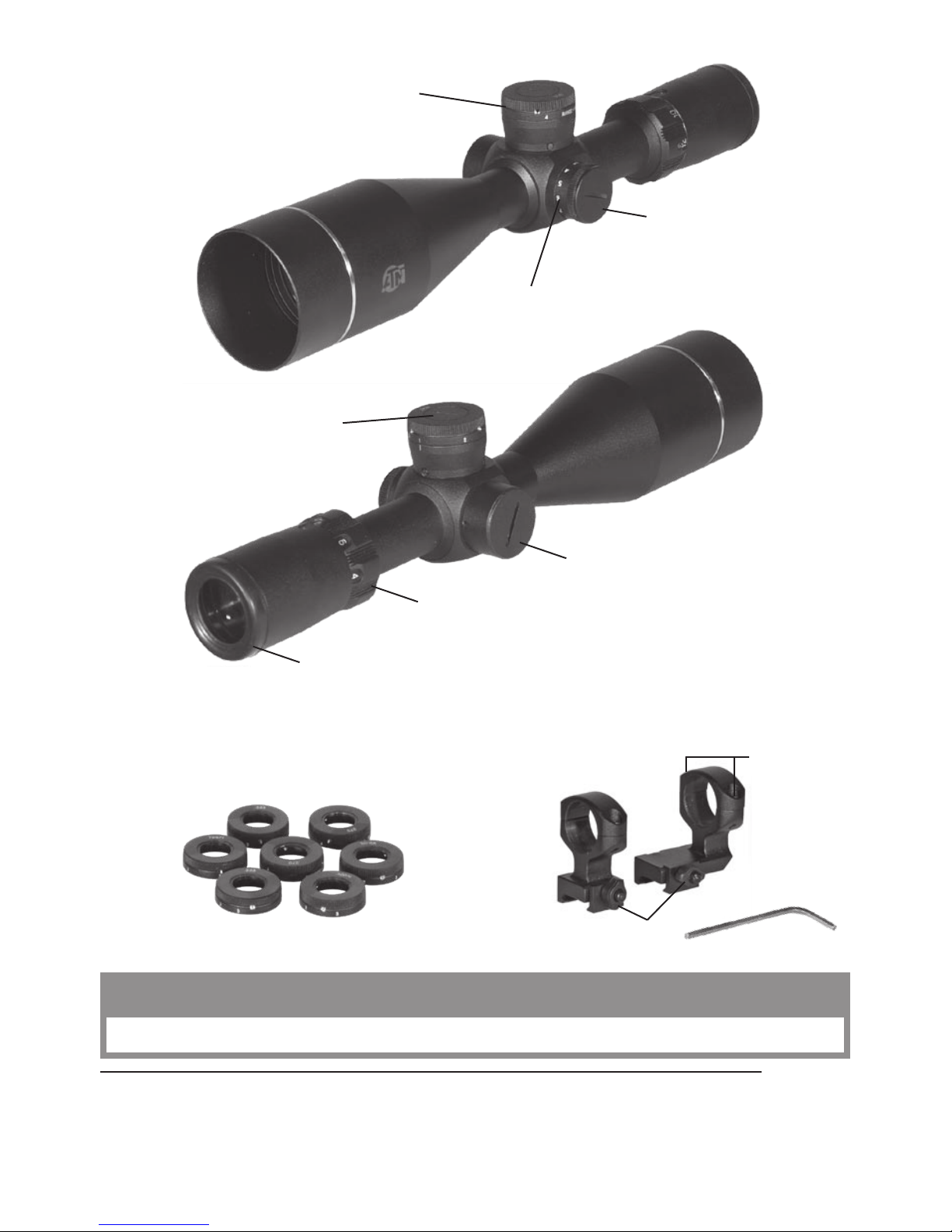
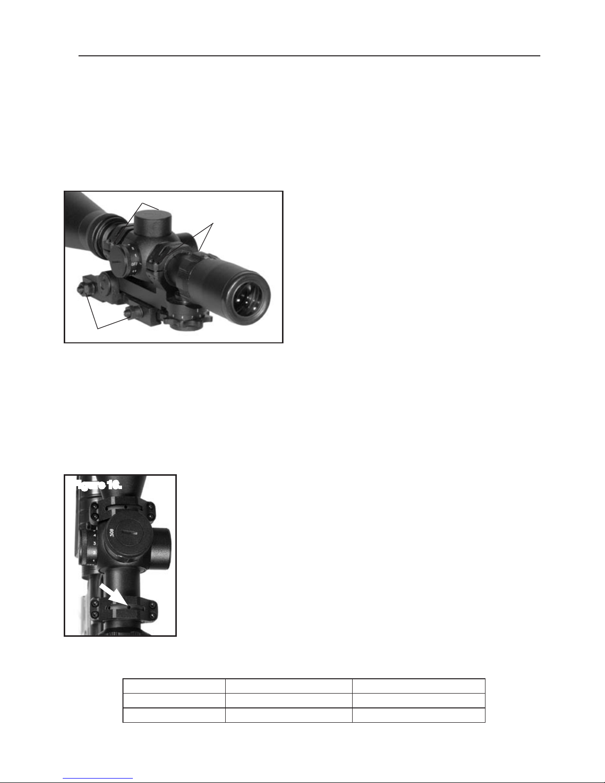
Bullet drOP cOMPeNsatOr:
Yo u s h ou ld h ave z e ro e d yo ur s c op e at 10 0 ya r ds . Wh en sh oo ti ng at l on g er
ranges the bullet drop compensator should be adjusted for 200, 300,
400, and 500 yards ( and 1000 yards for 8-24x65LU and 12-36x80LU).
Depending on the distance click the bullet drop compensator to the
appro priate setting. This will automatically adjust your reticle for that par-
ticular distance. Your scope also comes with other cams allowing you to
change your bullet drop compensator to work with the different rifles.
NOTE: 12-36x80 has special mechanism for bullet drop compensation
with compensator for .50 BMG. Compensator provides shooting at the
distance from 200 up to 3000 yards. (See page 7 for instuctions.)
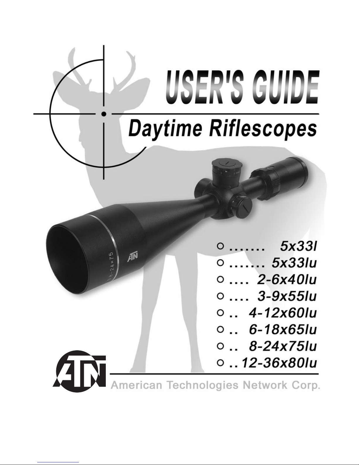
To set the necessary distance combine the figure with the mark on the immovable upper part of the
mechanism.
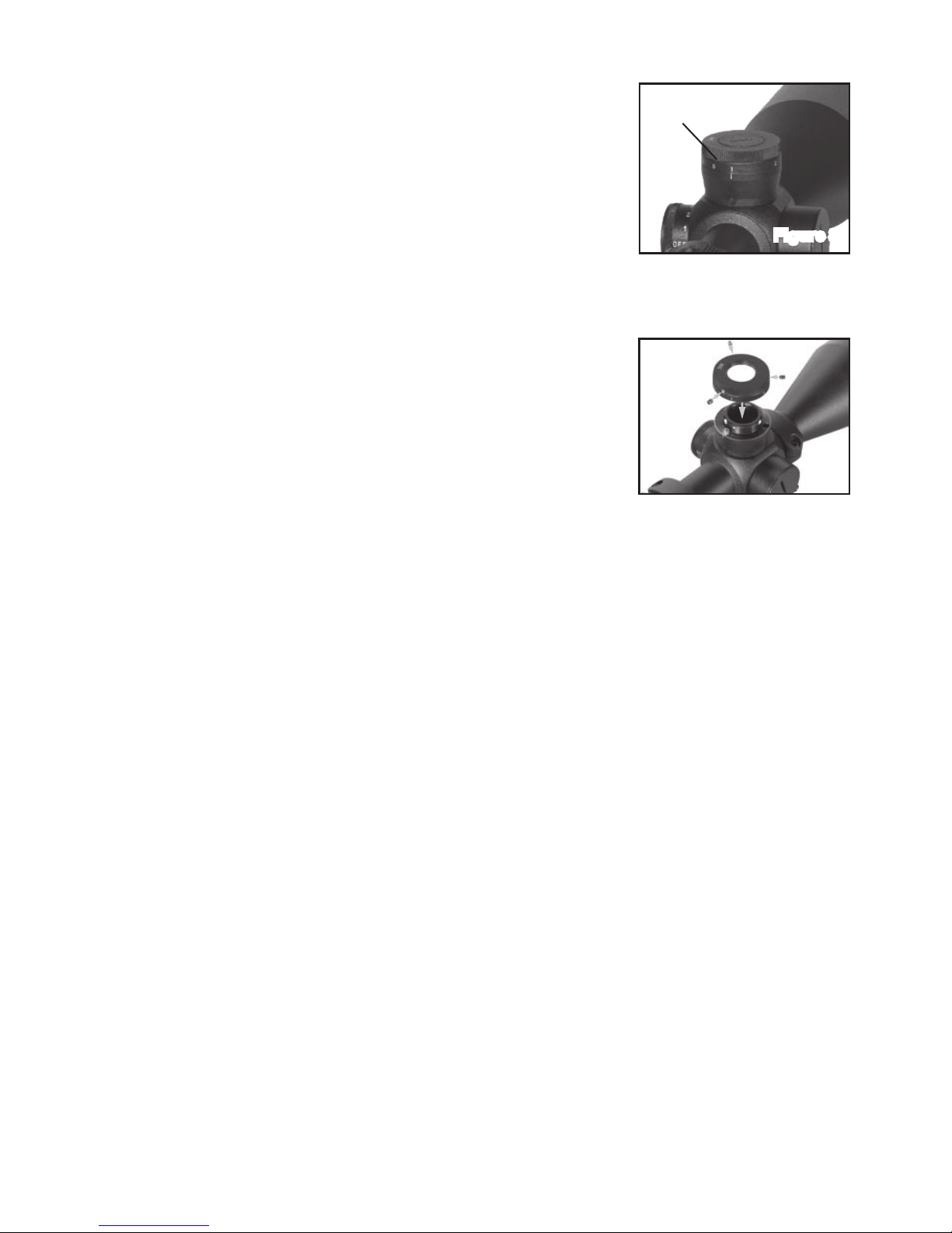
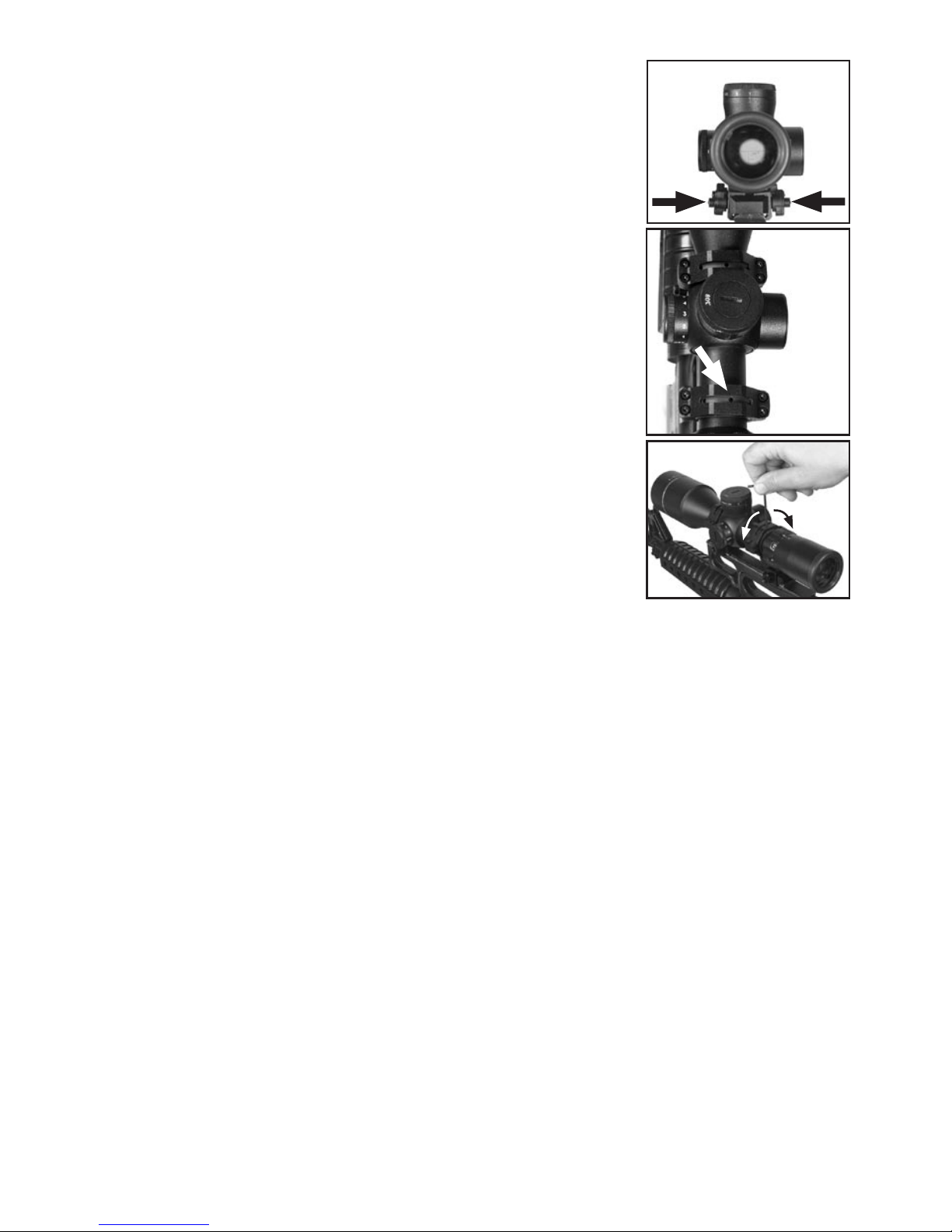
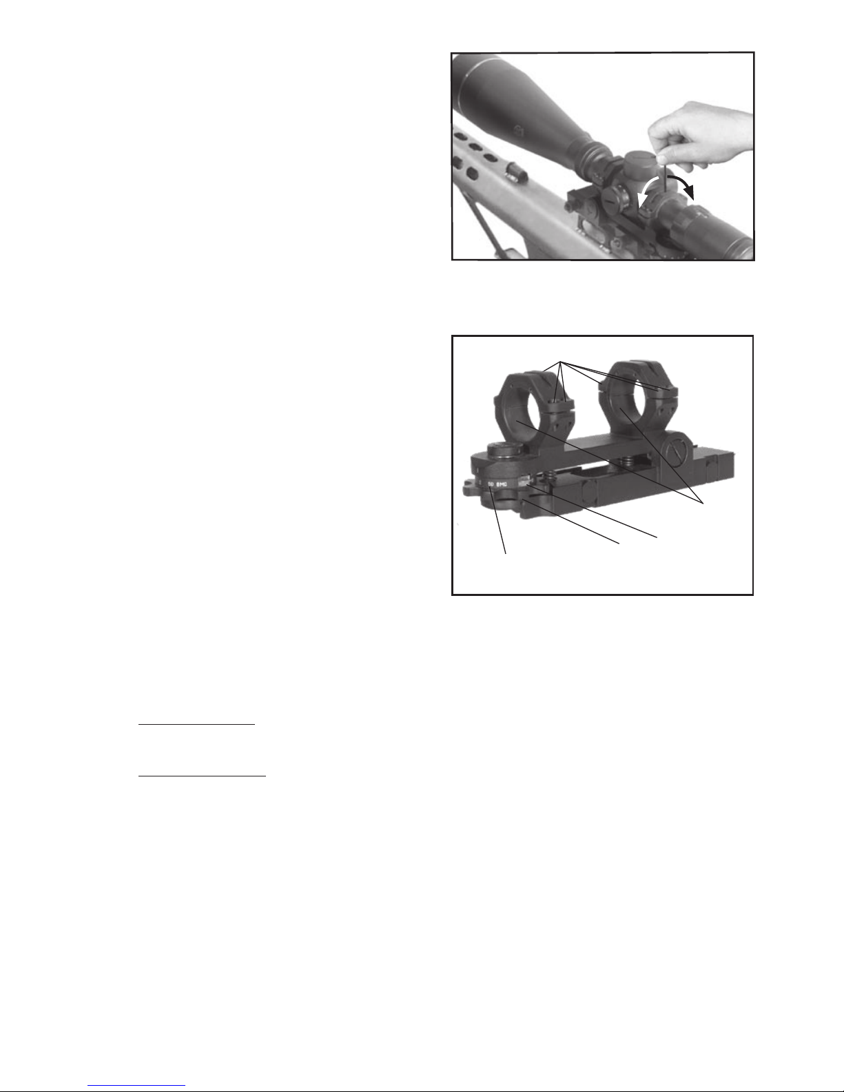
chaNGING the Bullet drOP cOMPeNsatOr
Set the bullet drop compensator to the 100-yards (5x33LU, 2-6x40LU,
3-9x55LU, 4-12x60LU) or 200 yards (4-12x75LU, 6-18x65LU) range.
Then remove the elevation dust cover. Next you will find three small set
screws on the bullet drop compensator right above the yardage numbers.
Remove these screws and lift the cam off of the scope. (Fig.9) Once you
have done this select the desired caliber cam you would like to use and
place this cam where you removed the previous one (make sure that a
replacement cam is set to the 100-yard range for 5x33LU, 2-6x40LU,
3-9x55LU, 4-12x60LU and 200 yards for 4-12x75LU, 6-18x65LU). Then
tighten the cam by putting the three set screws back. Finally place the
dust back.
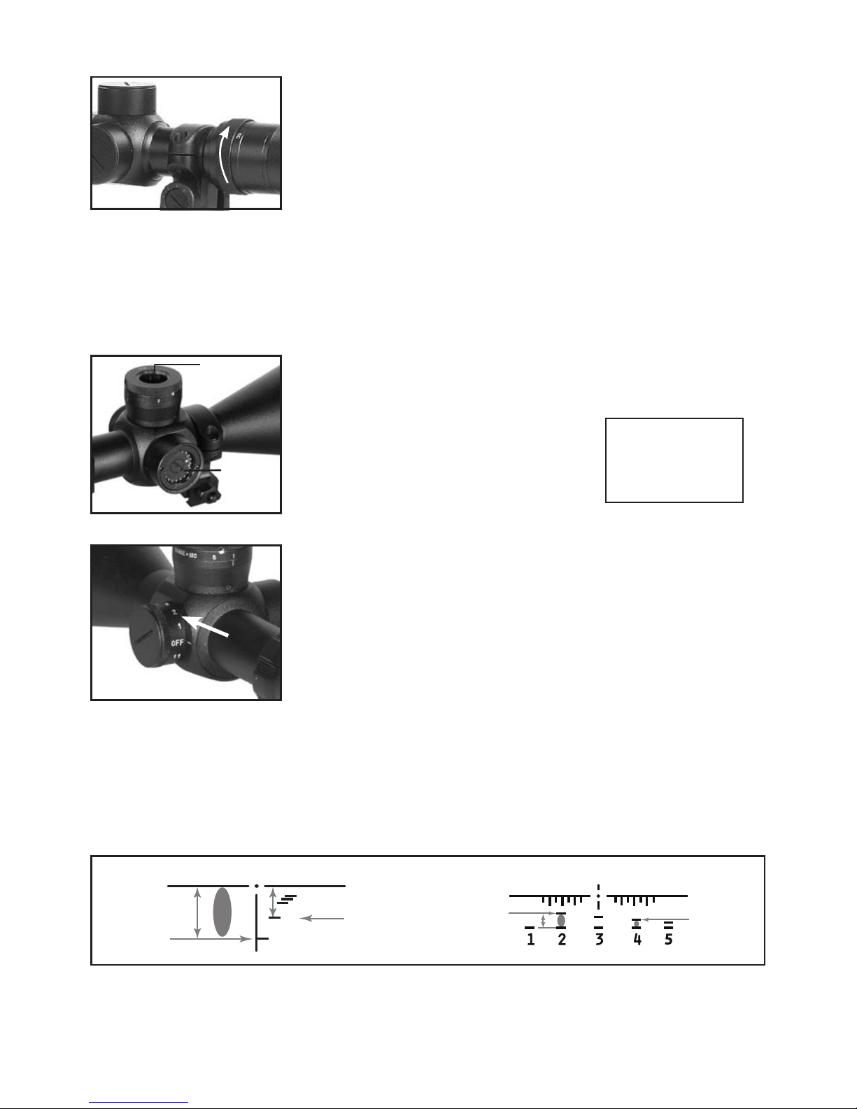
retIcle systeM:
Upon initial use of the ATN Professional Variable Power scope you may notice a somewhat unusual
behaviour of the reticle system. One, the reticle will increase or decrease with the power change. Two,
the reticle will move from the center when you adjust windage and/or elevation. These are not defects.
As the name implies, our main goal while designing this line was to provide the customer with the most
accurate and reliable sighting system in the world. In order to achieve this, we had to depar t from the
more “conventional” designs that the American consumers are so familiar with.
retIcle chaNGING sIze:
In any optical design the reticle has to be placed either in the front focal plane or the rear focal plane
(the only exception to this rule are the Shepherd scopes that contain two reticles, one in each plane).
The rear focal plane, or behind the magnification module, was the initial and less complicated, as well
as less expensive solution. Up to this day, almost all American scopes and inexpensive imports uti-
lize this design. However, there is an inherent flaw in this type of system. Because the magnification
module is housed within sliding mechanical parts, some tolerance for lateral and vertical movement has
to be allowed. Therefore, when the power is changed the point of impact may shift as much as several
inches. A more reliable design is to place reticle in the front focal plane, i.e. in front of the magnification
module. In this situation movement of the module will have no effect on the point of impact. The reticle
will increase/decrease in direct proportion to magnification, i.e. if you change the magnification from 6x
to 18x, the image is increased three times and the reticle along with it. The size of the reticle in relation to
size of the target will not change. The point of impact remains constant at all times.
MOvING retIcle
A somewhat similar situation take place with windage and elevation adjustments.
Most of the American scopes and low-priced imports adjust the front tube for windage and elevation.
This action moves the whole image while the reticle remains in apparent center. While aesthetically
appealing, this system lacks inherent accuracy.
In the Professional series, windage and elevation adjustments are effected by moving the reticle itself.
Since in our system the objective lens is fixed, there will never be any distor tion, which may appear while
moving the front tube of the scope. Further more, since the reticle weighs only a few grams, it allows
for extremely precise (1/8” at 100 yards), reliable, and repeatable adjustments. The optical effect of
this system is that the reticle will not be located in the center once sighting in has been accomplished.
This situation can be remedied however through the use of vertical and horizontal shims available any
gunsmith.
Figure 9
Bullet drop
compensator
Figure 8