[1]
[2]
[3]
[4]
[5]
[6]
[7]
[8]
[9]
CONTENTS
Introduction.....................................
eee
semen
eessasennnansnn
1
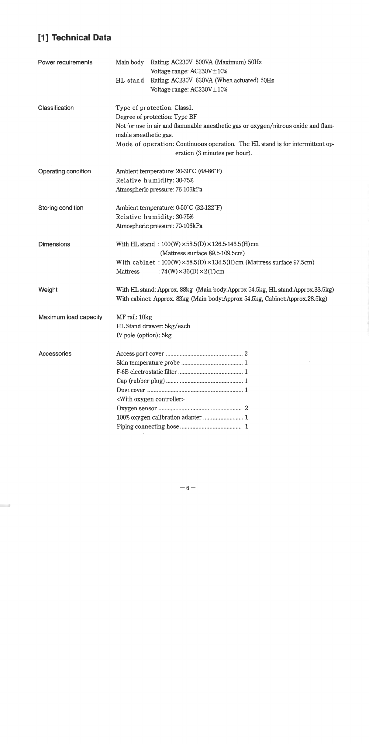
TechnicalData....................................................
eee
6
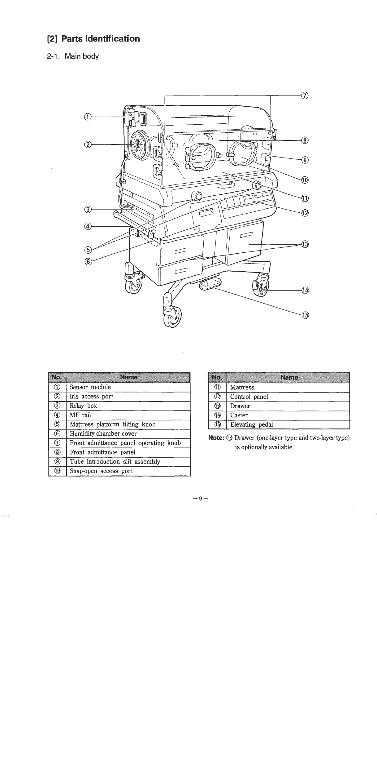
Parts
Identification
2-1.
Mainbody..................
eee
ere
eeezi
eee
cenere
ie
eee
eee
cei
re
nin
ezine
cazione
nere
9
2-2.
Control
Panel...
sise
11
Troubleshooting
3-1.
Troubleshooting
in
control
failure
rire
13
3-2.
Troubleshooting
in
system
malfunction
.............
irene
15
Cleaning,
Disinfection
and
Maintenance
4-1.
H00d
ennemies
20
4-2.
Mattress
Platform
and
Parts
Beneath
....................
rin
22
4-3,
Others
i...
ϱϱϱϱ”ϱ”ϱ-.--
24
4-4,
Humidity
Chamber
rire
iii
24
4-5.
Replacing
the
Filter
ss
26
4-6.
Replacing
the
Oxygen
Sensor
nn
27
Inspection
sn
29
Replacing
the
fuse
and
the
battery
.pe
36
SettingtheDIP
switch........................................................
emen
38
Periodical
replacement
partS
eee
39
Block
Diagram
and
Wiring
Diagram
.pe
41
Replacement
Parts
List...
ger
43