ATOMSTACK Cambrian User manual

English
Deutsche
Français
Shenzhen AtomStack Technologies Co., Ltd.
www.atomstack3d.com

Table of Contents
1. Precautions and Disclaimer........................3
2. Device introduction....................................4
3. Tools and accessories..............................5
4. Pre-assembly inspection..........................6
5. Structure assembling...............................7
5.1 Step1: Z-Axis assembling.............................7
5.2 Step2: LCD screen assembling.......................8
5.3 Step3: Material bracket assembling................9
5.4 Step4: Handle assembling...........................10
5.5 Step5: Cable connectivity ...........................11
6. Printing extruder replacement method..12
7. LCD interface introduction......................13
8. Software configuration...........................14
8.1 Software installation.................................14
8.2 Step1: Printer configuration..................15~16
8.3 Step2: Material configuration......................17
8.4 Step3: Slice files configuration.....................18
9. Printing File Preparation ................................19
9.1 Slice files parameter introduction.......................19
9.2 Creating the Slice files....................................20
10. Inspection of Structure..............................21
10.1 Printer inspection before printing........................21
10.2 Scroll wheel inspection ...................................22
10.3 Transmission belt Inspection .............................23
10.4 Extruder nozzle cleaning..................................24
10.5 Levelling adjustment......................................25
11. Material preparation.....................................26
11.1 Prepare to load the material..............................26
11.2 Loading the material ......................................27
12. Start printing................................................28
13. Finish printing...............................................29

1.Precautions and Disclaimer
1.Astomstack 3D printer has two types of voltage mode, AC 115V & AC 230V, please switch to the suitable voltage to your electric circuit by manual to prevent the damage
of equipment. Must use with the ground wire power source.
2.Do not place the printer where there are flammable and explosive materials. Make sure that there is no other vibration source where the printer is located to ensure the
stability of the printer. The ambient temperature is 25℃, and the relative humidity is 20%RH~50%RH
3.For your safty, please DO NOT touch any part of the printer during building prevent from harmful by hit or pinch.Temperature at the nozzle could 250℃ and the head
bed could be 90℃, please stay away from them during printing.
4.Please clean the extruder and nozzle after each printing, caution because the nozzle could be very hot. Make sure it is power off before cleaning, please clean by the tools privided with the printer.
Please clean the printer with dry clean rag.
5. This product is not a toy, nor is it suitable for people under 15 years of age. Do not allow children to touch the printer. Please be careful when performing scene
operations with children. Be careful not to pinch your hands during installation and use. Any pinch will not be held responsible. Before using this product, please read this
document carefully to understand Your legal rights, responsibilities and safety instructions; otherwise it may cause property damage, safety accidents and personal safety
hazards. Once you use this product, you should be deemed to have understood, accepted and accepted all the terms and contents of this document. The user is
responsible for his or her actions and all consequences arising therefrom. The user agrees to use the product for legitimate purposes only, and agrees to all the terms and
contents of this document and any related policies or guidelines that AtomStack may establish. Shenzhen AtomStack Technology Co., Ltd. reserves the right to update this
disclaimer and safety operation guide. AtomStack is not responsible for any and all losses caused by the user’s failure to use this product due to the user’s use of this
product. AtomStack has the final right to interpret the documents and comply with legal requirements. AtomStack reserves the right to update, modify or terminate the
terms without prior notice.

2.Device introduction
X-Axis belt adjustment knob
Extruder
(Pre-set E285 extruder)
Y-Axis belt adjustment
knob
Y-Axis Eccentric nut
X-Axis Eccentric nut
TF card slot
at LCD
Switch
Levelling adjustment
wheel
Support bracket
AtomStack
Material
bracket
Loading Handle
TF card slot
at machine USB port
Nozzle
LCD
Handle
Heating bed
Introduction
Printer
volume
235*235*250mm
Power
supply
AC100~240V 50/60HZ
Operation
Software
Ultimaker Cura
Support OS
macOS、Windows&Linux
Material
bracket

3.Tools and accessories
Shovel
Socket wrench for
replacement of
nozzle
hexagonal wrench
for assembling
Wrench for the
levelling adjustment
TF memory card
including the printer object
file and configuration
instructioin video etc.
TF card reader
reading file
Through needle
for cleaning of nozzle
E175printing extruder
1.75mmfilament,0.4mm
nozzle.For PLA,PETG printing
Cutting pliers
for filament
E285 printing extruder
for 2.855mm filament,0.4mm
nozzle.For TPR printing
screwdriver used for
disassembling
FFC cable plug

1.The power switch of 3D printer has two types of voltage mode,
AC 115V & AC 230V, please switch to the suitable voltage to your
electric circuit by manual at the bottom .
4. Pre-assembly inspection
Bottom of printer Switch of voltage
2.we will set the positioning pin in order to keep the Z-axis part with the firm
position before package at the Z-axis.Please remove the position pin before
assembling
Z-axis parts
Pos it i o n P I N
Z - ax i s ( l e f t ) Z - ax i s ( r i g h t )
Z轴(左)
Pos it i o n P i n
Re move t h e
po si t i on P I N

Instruction
1.Put the Z-axis vertical into the groove at the base
2.Use 4pcs M5*44 screw to fasten from the bottom of base
with the Z-axis
1
2
G ro o ve
3
1 . Z - a x i s p a r t ( w i t h E 2 8 5 ) 2 . B a s e 3 . M 5 * 4 4 s c r e w *4 P C S
Assembling parts
5. Structure assembling
5.1 Step1 Z-Axis assembling

Fasten the LCD at the right of base with the screw
5*14
1
2
Assembling Parts
1 . L C D * 1 P C S 2 . M 5 * 1 4 s c r e w * 2 P C S
Instruction
5.2 Step2: LCD screen assembling

Fasten the brack on the beam with M5*14 screw*2PCS
2
Assembling Parts
1 . b r a c k e t * 1 P C S 2 . M 5 * 1 4 s c r e w * 2 P C S
Instruction
1
5.3 Step3 Material bracket
assembling

Fasten the handle on the beam with the screws of
M5*2pcs
Instruction
Assembling Parts
1 . h a n d l e * 1 P C S 2 . M 5 * 2 5 s c r e w * 2 P C S
2
1
5.4 Step4: Handle assembling

1.Vertically insert the cable of Z-axis into the port of base
2.Horizontally insert the cable of Z-axis into the port of both motors
3.Vertically up insert the cable of limitation switch into the power
switch port
4.Insert the power cable.
Instruction
F FC ca bl e
Ver ti cal ly
in se rt t h e
cab le i nto
t h e p o r t o f
b a s e
5.5 Step5: Cable connectivity
mo to r at r i g ht
L i mi tat io n
s w i tc h
mo to r at l ef t Limitation switch
Z-axis motor
connectivity
FFC connectivity Z-axis parts connectivity
Power ca bl e
S w i tc h
E285 extruder

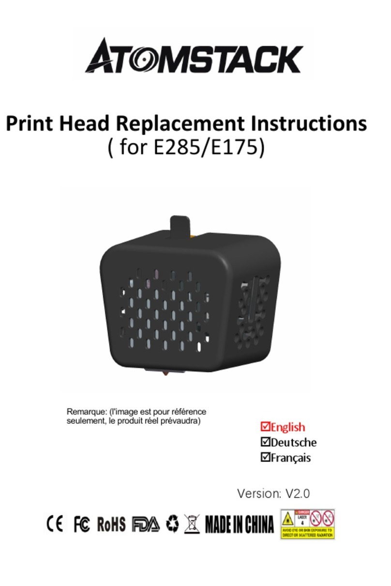
6.Printing Extruder replacement Method( for E285/E175)
Toggle the cable buckle upward and
remove the FFC cable
loosen the screws
screwdriver
hexagonal wrench
2.Unlock and unplug the FFC cable
The connection between the side port of the print head and the FFC cable is a snap-
clamping method. Use the configuration tool screwdriver to insert from the side end of the
print head (as shown in the figure below) to the two ends of the line buckle, and then pick
up the buckles respectively and take them out FFC cable.
3.Insert the FFC wire into the new extruder
Carefully insert the FFC cable into the buckle, and press down the left and
right ends of the buckle with a screwdriver.
4.Assemble the new extruder
Aim the screw holes on the back plate and fasten the extruder
ba ck p late
ba ck p late
screw holes
F FC ca bl e
ex t r u d e r
screwdriver
s c r e w d r i v e r
ex t r u d e r
p l u g cab le
b u c k l e
Remark: The default extruder of 3D printer is E285, this page is the instruction for
change the E285 to E175. E285 is for TPR 2.85mm filament, E175 is for PLA/PETG
1.75mm filament.
1.Remove the existing extruder
There is 3pcs fixed screw at the back of extruder, use the hexagonal wrench to
loosen the screw ( no need to remove ), and then take out the existing extruder.

1.Click the button to unfold or fold the menu list to set the parameter of printing temperature,heat bed temperature, fan speed etc by manual.
2.Click “Print”to select the object file you need to print, our printer is only available with “Gcode”format at present.
3.Click “Extruder”to set the material feeding and retreating by manual.
4.Click “Move”to control the movement of X/Y/Z Axis beam, and balance adjustment of heat bed.
5.Click”Settings”to change different language,reset etc.
7.LCD interface introduction
Status list
Button part
Settings area
Button for unfold and fold
Print Extruder Move Settings
7.1 LCD button function introduce

8. Software configuration
8.1 Software installation
• AtomStack Cambrian uses Marlin open-source firmware, so any object software that supports Marlin firmware can be compatible with Cambrian printers. Here, our global
popular Ultimaker Cura software. Ultimaker Cura is an excellent open-source software that supports macOS, Windows, and Linux systems.
• Visit the following link to get Cura :https://ultimaker.com/software/ultimaker-cura. Please follow the instruction to finish the installation after downloading the software.
There are 3 sections configuration of Cura for AtomStack Cambrian A: Printer configuration B.Material configuration C.Object parameter configuration(All the necessary
document, configuration file, and video is in the TF card). Cambrian Pro has equipped two different extruders, AtomStack E285 E3 extruder(for TPR filament or any other
2.85mm filament diameter)and AtomStack E175 H2 extruder(for PLA PETG, etc. any other 1.75mm filament diameter). And the diameter of the nozzle is also different,
E285 E3 is 0.8mm,E175 H2 is 0.4mm,we already set the parameter for each nozzle. For the following instruction, we will configure based on the TPR material with
AtomStack E285 E3 extruder to show the configuration, likewise, you can configure E175 H2 by following the steps 8.2~8.4,please pay attention that the parameters of
the two extruders are different,you need to configure by the correct configuration file. You can also visit our website to obtain the latest You can also visit our official
website:http://atomstack3d.com/3dprinterdownload to get the latest motherboard firmware, screen firmware, configuration files, manuals, and other information (Note:
For data version upgrades or updates, please pay attention to get the latest version in time)

8.2 Step1: Printer configuration
1. Load the Cura software, under the "PREPARE" tab, expand the
device list, and click the "Add a printer" button
2. Unfold the "Add a non-networked printer" list in the pop-up
window
3. In the expanded list, select the "Custom" group, check the
"Custom FFF Printer" radio button, then change the printer name to
"Cambrian Pro E285" on the right page, and finally click the "Add"
button
4. In the pop-up window, under the "Printer" tab, set the
parameters of "Printer Settings" as shown in the figure, X:235mm
Y:235mm Z:250mm, heating bed selection "√", G-code style
selection "Marlin.

5. On the "Printer" options page, delete the codes in Start G-
code and End G-code respectively, and then find the "CUSTOM"
package from the data package of the gift TF card and open it in
sequence 1. "Custom Files ”> 2. “Cura config file”> 3. “Printer
Start&End Gcode” is opened, and then copy the Start G-code
and End G-code codes to the code are shown in the figure
(E285 and E175 printers need to be copied and added Start G-
code and End G-code code)
6. Under the "Extruder1" tab, set the nozzle parameters
according to the currently installed nozzle specifications. The
above picture shows the parameter configuration of the nozzle
for printing E285 material. Nozzle aperture: 0.8mm, compatible
material diameter: 2.85mm (E175 material printer nozzle
Aperture: 0.4mm, compatible material diameter: 1.75mm)

1. Under the "PREPARE" tab, expand the drop-down list of
materials indicated by the numbers "2" and "3" in turn, and
click the "Manage Materials..." button to enter the material
management page
2. In the pop-up window, click the "Import" button, select the
"CUSTOM" package in the attached TF card information, and click 1.
"Cura configfile" 2. "Material Configs" to find the file with the suffix
"fdm_material" File and double-click the file name. Take TPR
60.xml.fdm_material as an example here.
3. Click "OK" in the pop-up window to complete the import of
materials
4. You can see the imported materials under the "AtomStack" group
in the list
8.3 Step2: Material configuration

1. Under the "PREPARE" tab, click the parameter menu
prompted by the number "2", and click the "Custom" button
in the expanded page
2. In the pop-up page, click the triangle shown by the number
"1" to expand the Sliced parameter list, and click the
"Manager Profiles..." button at the bottom
3. In the pop-up window, click the "Import" button, select the
"CUSTOM" package found in the attached TF card data package, and
open it in order 1. "Custom Files" 2. "Cura config file" 3. "Printing
Profiles" Find the file with the file suffix ".curaprofile" and double-click
the file name to complete the (PLA/TPR) slice parameter import
4. Under the "Custom profiles" group in the operation list
on the left, you can find the Sliced parameters you just
imported. Here we take "Cambrian TPR45.curaprofile" as an
example
8.4 Step3: Slice files configuration

9.Printing File Preparation
9.1 Slice files parameter introduction
• After we finish the configuration of Ultimaker Cura, we get everything ready except the 3D printing file
• Ultimaker Cura software supports 3D data formats in various formats such as .stl/.obj/.3mf/.poly. You can perform 3D modeling with your familiar modeling software, and then
export the built model into these formats File. At present, most modeling software such as ProE, AutoCAD, Maya, ZBrush, SketchUp, etc. can export one or more of the above
formats.
• It’s okay if you don’t want to model. There are many model-sharing sites on which you can download and print a lot of interesting models. The biggest platform is Thingiverse. Their
website is https://www.thingiverse.com There are tens of thousands of models on this website that can be downloaded for free. Of course, if you have some interesting designs,
you can also share them on this platform so that everyone can benefit from your creativity.
• In the TF card delivered by the Cambrian printer, we have also pre-stored some interesting models, you can also try to type these models.
• After the 3D model is imported into the Ultimaker Cura software, the Cura software will first convert the 3D model into a 2D graphics file, which we call "slices". The 2D files
generated by the slices are called "slice files" or "slice data". The format is ".gcode" format, Cambrian printer only recognizes ".gcode" files.

1. Under the "PREPARE" tab, click the Import button shown by
the number "2", and in the pop-up window, select the model
you want to print and double-click to complete the import
2. After importing the model, if the model exceeds the printing
boundary, the model will be gray. Click the tool button on the
left side of the software to adjust the size, position, and angle
of the model
3. After adjusting the model, select the materials you want to
print and the corresponding printing parameters in turn as
shown in the figure, and then click "Slice" to start generating the
print data, that is, slices
4. After the slicing is completed, insert the card reader and TF
card, and save the slicing data to the TF card as shown in the
figure. Now, we have completed the production of the print
data
9.2 Creating the Slice files
Table of contents
Languages:
Other ATOMSTACK 3D Printer manuals