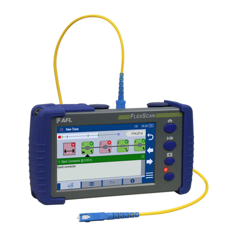
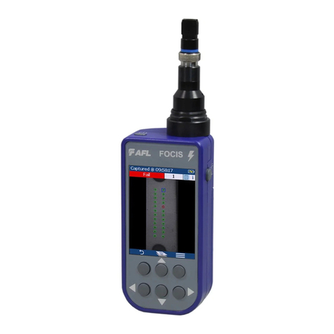
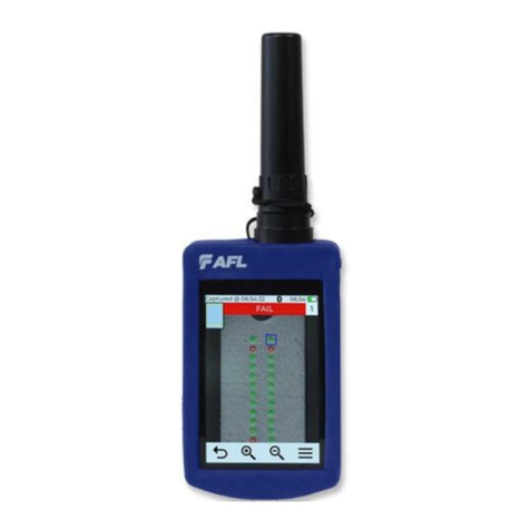
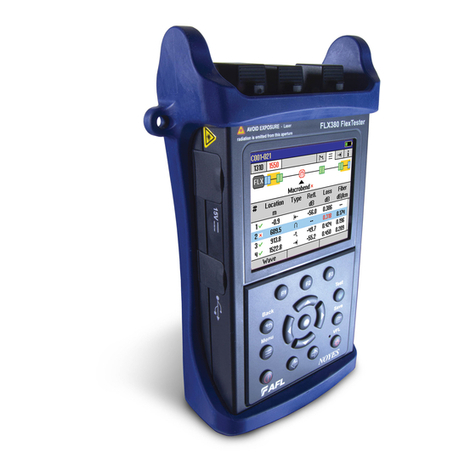
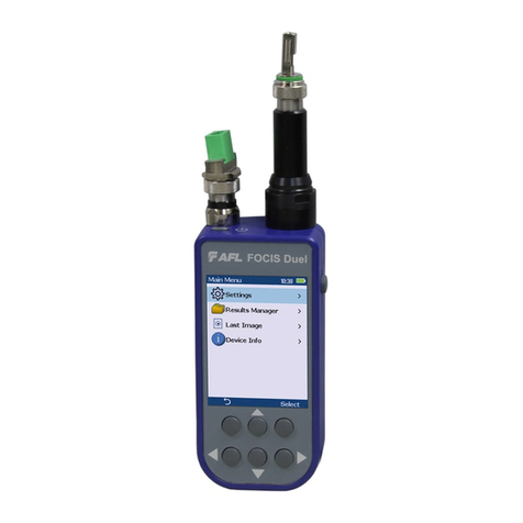
AFL M710 Series Installation instructions

www.AFLglobal.com, +1 (800) 321-5298 or +1 (603) 528-7780
Test & Inspection
M710-Series OTDRs
with LinkMap®
User’s Guide

2
Table of Contents
OTDR Software Options ........................................ 4
DFS1 Digital FiberScope.............................................4
TRM®(Test Results Manager) Trace Analysis and Reporting PC Software........4
TruEvent®Event Analysis Technology...................................4
LinkMap®with Pass/Fail ............................................4
Hardware Overview............................................ 5
Controls, Ports, and Features.........................................5
Front Panel Keys and Indicators.......................................7
User Interface Overview ........................................ 9
Main Menu . . . . . . . . . . . . . . . . . . . . . . . . . . . . . . . . . . . . . . . . . . . . . . . . . . . . . .9
Test Modes Settings Summary......................................10
Utility Modes Summary ...........................................10
Selecting Operating Mode from the Main Menu ........................11
Display Features ..................................................12
Test Pages Tabs Legend.............................................13
General Settings .............................................. 14
New Job Utility ............................................... 15
New Job Overview ................................................15
New Job Creation .................................................16
OTDR Test Settings ............................................ 17
Full Auto Mode Settings ............................................17
Expert Mode Settings ..............................................18
Real-Time Mode Settings............................................19
Event Settings ................................................ 20
Event Settings Overview ............................................20
Setup Parameters Available in Full Auto Mode..........................20
Setup Parameters Available in Expert Mode ...........................20
Setup Parameters Available in Real-Time Mode .........................21
Navigating Through Event Setting Menu ................................22
Pass/Fail Settings .................................................23
OPM Test Settings ............................................. 24
OPM Home Page Indicators..........................................24
Soft Keys/Touchscreen Icons .........................................25
Results Manager .............................................. 26
Results Manager Overview ..........................................26
Test Results Icons Legend .........................................26
Results Manager “File Tree” Structure................................27
Cut/Copy/Paste Features ..........................................28
Rename Feature ................................................29
Job Creation in Results Manager ......................................30
Job Selection from Results Manager ...................................31
Job Selection from a Test Mode .......................................32
©2016, AFL, all rights reserved. M710-00-1000 Revision 1B, 2016-04-19
Specications are subject to change without notice.

3
Opening Test Results for Review ......................................33
OTDR Testing ................................................. 34
Running OTDR Tests ...............................................34
How to Perform an OTDR Test ........................................35
How to Save an OTDR Test ..........................................36
Front Panel and First Connector Check .................................37
OTDR Test Results Viewer ....................................... 38
Trace Viewer Features ..............................................38
LinkMap Viewer Features ...........................................40
Event Icons and Types ............................................42
Soft Keys Definitions and Functions....................................43
Wavelength Selection Menu In OTDR Pages .............................44
View Results in Trace Page ..........................................46
View Results in Event Table ..........................................47
Event Table Data ................................................48
Event Icons and Types ............................................48
View Results in Summary Page .......................................48
How to Switch Test Data Column Sets in Summary Page ..................49
Column Set - “Loss Cols” .........................................49
Column Set - “Max Cols” .........................................49
Re-Calculate Events..............................................50
Full Auto Mode: Fault Locating .......................................51
Two Point A/B Measurement .........................................51
OPM Operation - Testing Multimode/Single-mode Links............... 52
Step I - Set the Reference (One Jumper Method) ..........................52
Step II - Verify Test Jumpers .........................................52
Step III - Measure Link Insertion Loss...................................53
Text Editor ................................................... 54
Transferring Files.............................................. 55
From OTDR via USB Memory Stick to a PC ...............................55
From OTDR via Mini-USB Function Port to a PC ...........................55
Recommended Accessories ...................................... 56
Cleaning Tips ................................................. 57
FAQs ........................................................ 59
Tips: Expert OTDR Setup ........................................ 59
Recharging Batteries........................................... 60
Repair and Calibration ......................................... 60
Limited Warranty.............................................. 62
Contact Us ................................................... 62
Software Information .......................................... 62
Safety Information ............................................ 63
Table of Contents

4
OTDR Software Options
• A CD containing TRM 2.0 is included with every OTDR. The CD jacket has a sticker with a license
activation key for TRM Basic Software (OTDR Trace/OLTS viewer, Batch Editor, and Reports). The
activation key is good for up to ve fulllments to allow multiple PCs to run TRM 2.0 Basic.
The multiple fulllments also allows a user to activate TRM 2.0 Basic when changing to a new
PC. Once the ve fulllments have been used for a license key, the user must purchase a new
license, which will provide a new activation key good for ve fulllments.
• To install TRM Basic on additional PCs, additional licenses of TRM Basic Software may be
purchased by ordering part number TRM-00-0900PR.
• A single license version of TRM Advanced Software (incudes TRM Basic plus Advanced Analysis
for PC) is included with every M710 OTDR. If additional licenses needed, they may be purchased
by ordering part number TRM-00-0910PR.
• To upgrade from TRM Basic to TRM Advanced software a single license version may be
purchased by ordering part number TRM-00-0920PR.
The M710 OTDRs utilize AFL’s industry leading TruEvent technology to provide a new level of
accuracy and reliability in event analysis. Events on a ber include connectors, splices, optical
splitters and macro-bends. To accurately locate an event, OTDRs need to nd its location, identify
event type, measure reectivity and loss. AFL’s M710 OTDR with TruEvent technology provides
better baseline documentation of ber links and enables the user to troubleshoot faulty networks
more effectively.
DFS1 Digital FiberScope
TRM®(Test Results Manager) Trace Analysis and Reporting PC Software
TruEvent®Event Analysis Technology
DFS1 software and license comes standard with OTDR.
DFS1 Digital FiberScope is an optional accessory.
LinkMap®with Pass/Fail
The M710 LinkMap with Pass/Fail enables even novice users to easily and accurately troubleshoot
optical networks. LinkMap presents an icon-based view of the tested network clearly identifying
ber start, end, connectors, splices and macro-bends. A LinkMap Summary provides end-to-end link
length, loss, and ORL. Loss and reectance of detected events is compared to industry-standard or
user-settable pass/fail thresholds and displayed with clear pass/fail indications.

5
Hardware Overview
Controls, Ports, and Features
Ref Control/Feature Description
1 OTDR ports These are CLASS I LASER outputs
2 VFL port This is a CLASS II LASER output. Do not stare into beam.
The VFL (visual fault locator) port is a 650 nm (red) laser. Used for
short-range fault-location.
3 OPM port Optical Power Meter port.
Used for power (dBm, W) or loss (dB) measurements.
4 Dust cap Used to protect optical ports from dust/damage.
5 Boot A proven shock-absorbing rubber boot.
6 Touchscreen display Contains on-screen controls and menus. Used to show setup
menus, test results, and saved test data information.
7 Hard function keys These are the hard function keys and indicators. See section “Front
Panel Keys and Indicators” on page 7 for details.
8 Soft function keys These are soft function keys. See section “Front Panel Keys and
Indicators” on page 7 for details.
Front Panel View
Top Panel View
7
8
1 53425
6

6
Hardware Overview
Controls, Ports, and Features
Left Side View Right Side View
Back Side View
Ref Control/
Feature
Description
1 Power port This is interface for the AC power adapter/charger.
2 Mini-USB
function port
This port may be used to connect OTDR to a USB host port on PC with the
supplied cable.
3 USB function
port
This USB port allows connection to a PC for transferring stored test results.
Also this port may be used to connect USB Flash Drive for data storage and
copying Internal les.
4 Tilt stand Surface-top tilt stand may be used for the convenience of operation.
5 Wrist strap Wrist strap is supplied with an OTDR and may be used for the convenience
of carry and operation.
6 Battery
compartment
Holds removable/rechargeable Li-ion battery.
Turn the door latch
A
down to unlock the battery compartment door, and
then lift the compartment door to access the battery compartment.
1
3
2
4
6
5
5
A

7
The use of each key is summarized in the table below.
Ref Symbol Key/Indicator Function
1AC Adapter/
Charger
indicator
This indicator Illuminates when the AC adapter/charger
is connected:
Red light ON indicates that battery is charging.
Green light ON indicates that battery is fully charged.
2Power key Press and hold (~1 second) to turn an OTDR on or off.
3 Power indicator This indicator Illuminates when the OTDR is turned on.
4VFL laser key ON 2 Hz - Press and hold (~2 seconds) LED will ash.
ON CW - Press and hold (~4 seconds) LED will be solid.
OFF - Press and hold (~1 second) LED should be OFF.
5VFL Indicator This indicator Illuminates when the VFL port is active.
Hardware Overview
Front Panel Keys and Indicators
2
4
8
9
11
3
7
12
5
6
10
13
14
1
15

8
Front Panel Keys and Indicators
Ref Symbol Key/Indicator Function
6 Menu key Press to access the Main Menu. The Menu Icon
must be displayed on the top bar for the key to perform
the action.
If you are at the top level the Menu key will be
disabled.
7Back key Press to return to previous page. The Back Icon
must be displayed on the top bar for the key to perform
the back action. If you are at the top level, the Back key
will be disabled.
8Five way
navigation
button cluster
The arrow keys provide several functions:
• In menus, these keys are used to navigate menus
and change setup parameters.
• In the Trace page, these keys are used to move
the cursors.
• In the Zoom Adjust page, these keys adjust
vertical and horizontal zoom levels.
• In the LSA Adjust page,t these keys move cursors
and adjust zoom levels.
9Enter key This key provides several functions:
• On the Main Menu page: press this key to open a
Test Mode, Results Manager, Settings, or New Job.
• On Settings pages: for setting followed by “...”,
press this key to open a submenu.
• On the Trace page: press this key to toggle
between A and B cursor.
10 Test key Press to start or stop an OTDR test, or toggle between
Live and Stopped in OPM testing.
11 Test indicator This indicator Illuminates RED to indicate test in
progress condition.
12 Save Press to save the currently displayed test results or
image using the current job settings.
13 Left and Right
Tab keys • Press to display the next/previous page in one of
the test modes: OTDR, OPM, or DFS.
• In text editor menus, press these keys to move
the cursor left or right.
14 Backlight key Press to set level of brightness.
15 Soft function
key
These are soft function keys. Press soft keys (or touch
labels on touch-screen) to perform the indicated
functions or expand menu.
Hardware Overview

9
Two types of modes are available from the Main Menu as follows:
TEST MODES: OTDR, OPM, DFS
Used to perform OTDR, OPM and Inspection
tests.
To select the desired mode
• Tap the appropriate Touchscreen icon.
• Use arrows to indicate the desired
mode icon, and then press key.
UTILITY MODES: Results, Settings, and New Job
Used to select user preferences, perform
general settings, create a new job (set up a
le structure and dene the ber under test
location), manage saved test results, and
perform other non-test functions.
To select the desired mode
• Tap the appropriate Touchscreen icon.
• Press the appropriate soft key located
below each Touchscreen icon.
Main Menu
User Interface Overview
Test modes icons
Utility modes icons

10
Menus Tip: “...” Function
Test Modes Settings Summary
Utility Modes Summary
Full Auto
(Automatic
OTDR)
Real-Time
(Real-time OTDR) Expert
(Manual OTDR)
OPM
(Optical Power
Meter)
Fiber type, launch and receive test cord lengths
Automatic or
default settings
Wavelength, range, pulse-width, resolution Wavelength
Automatic or
default settings
Averaging time Units (dB/dBm)
Event thresholds (Set) Reference
Results
(Saved Results)
Settings
(General Settings) New Job
(New or Existing Job)
OTDR
.sor
les
OPM
.atd
les
DFS
.jpg
les
Language,
Formatting,
Distance
Units,
Date, Time
Company
Name, etc.
Software
version
numbers
Create New or add to
existing Jobs
Reset all
Settings to
default
When a menu option is followed
by three dots “…”,
it means that there is a submenu/
page available. Press key
to display and see additional
information.
User Interface Overview

11
Mode Icon Description
Full Auto
OTDR
This is the recommended mode for users who are not familiar with
OTDR operation. In the Full Auto mode, OTDR parameters such
as Range, Pulse Width, and Averaging Time are set automatically.
Full Auto Tests are done at all available wavelengths and always
include an Event Table and Summary page. Pass/Fail Thresholds are
set to default with an option to be turned off.
Note: in the Expert mode, the Events Menu contains Event
Threshold and Pass/Fail Threshold Settings allowing the user to
change these settings and turn them on or off.
Expert
OTDR
This mode provides the most setup exibility. Auto-Once will set
Pulse Width, Range, and Averaging time for one test and then
return the OTDR to manual mode. Auto will select the Pulse Width,
Range and Averaging time for each test. Manual allows users to
set Range, Pulse Width, and Averaging Time manually. Users can
either enable the event table (Events = Auto) or disable the event
table (Events = Off).
Note: in the Expert mode, the Events Menu contains Event
Threshold and Pass/Fail Threshold Settings allowing the user to
change these settings and turn them on or off.
Real-Time
OTDR
This is the best mode for real-time troubleshooting. Note that the
Wavelength setting can only be set to individual wavelengths. The
Range and Pulse Width parameters are set by the user.
OPM This mode is available to perform Optical Power Meter
measurements.
DFS When the DFS1 is connected to an OTDR, this mode allows
users to inspect ber optic connector end-faces for damage or
contamination.
Results This mode provides le manager functions enabling users to open,
review and manage (cut/copy/paste/rename) stored results. Icons
show the stored results for each ber (OTDR, OPM, or end-face
image).
Settings This mode allows the user to adjust General Settings (Language,
Distance Units, Sounds, Auto Off function, Date/Time, Company
Name, Keyboard Style) and displays the OTDR version information.
New Job This mode is available for creating new jobs (setting up a le
structure and dening the ber under test location: Drives, Folders,
Jobs, Routes End Locations, Cables, Test Equipment Location, and
Operators).
Selecting Operating Mode from the Main Menu
User Interface Overview

12
Display Features
User Interface Overview
Ref Description
1Page header - Displays page name and test status.
2Battery status icon:
Green - fully charged
Red - discharged
Charging - AC connected
Fully Charged - AC connected
3Main Menu touch key.
4Back touch key.
5This eld indicates the currently displayed wavelength.
6Screen/Page tabs. Use Tab keys to change screens/pages.
7Menus and test results eld. Menus and test results are displayed in this area.
8Soft key labels and touch keys.
7
5
6
4
8
1 23

13
User Interface Overview
Test Pages Tabs Legend
1. Home - display OTDR setup, change Fiber and Cable ID parameters.
2. Test Settings - dene OTDR test setup.
3. Event Settings - dene OTDR Event settings and Pass/Fail settings.
4. Job Settings* - review current job settings.
* The Job Settings tab is included in each test mode as a convenience. Current Job settings can
also be viewed and changed using the New Job tool accessed from the Main Menu.
1. Home - display OPM setup; shows Live power or loss readings.
2. Loss Table - review results saved for the current cable.
3. Job Settings* - review current job settings.
1. Home Page - activate Live DFS mode and capture the displayed ber end-face image.
2. Results page - display captured end-face image; shows saved image of current ber or from
Results Manager.
3. Job Settings* - review current job settings.
When a test mode (OTDR or OPM) is enabled, your OTDR will display the ‘Home’ screen of the
enabled test mode.
• Use Tab keys to change test pages/screens available for the enabled test mode.
Full Auto/Expert OTDR mode Real-Time OTDR mode
OPM mode
DFS mode
1 2 3 4 1 2 4
1 2 3
1 2 3

14
General Settings
Press to select distance units of
measure.
Use arrows to toggle the Beeper
function On/Off.
Use arrows to dene the
Auto Off (set number of minutes)
function.
Press key to display submenu,
which allows the selection of
available languages.
Press key to display submenu,
which allows the selection of
available date/time/numbers
formatting options.
Press key to display submenu,
which allows setting Date.
Press key to display submenu,
which allows setting Time.
Press key to display submenu,
which allows dening Company
Name.
Use arrows to select keypad:
Alphanumeric or Qwerty.
Use arrows to select SOR version:
SOR Version 1 (GR-196-CORE) or SOR
Version 2 (SR-4731 Issue 2).
Press key to display Touch Panel
calibration screen.
Press key to reset all Settings to
the default values.
Use arrows to highlight the desired parameter
Press key to display the System
Information screen/Error Information
screen.

15
The New Job utility mode is available
for creating new jobs (setting up a le
structure and dening the ber under
test location: Drives, Folders, Jobs, Routes
End Locations, Cables, Test Equipment
Location, and Operators).
The New Job utility menu is accessed from
the Main Menu by tapping the New Job
Touchscreen icon or by pressing the New
Job soft key.
If the active job does not exist in the job
hierarchy, the new job creation screen will
start with all settings set to “--”(none) .
In the new job creation screen, the user is
allowed to:
• Create a new job and make the newly
created job “Active”.
• Create multiple new Jobs, Routes, or
Cables without closing the screen. Then
select one of the newly created jobs
and make it “Active”.
• Add, remove, and modify static lists
associated with each job setting.
To create a New Job:
• Use arrows to navigate up/down the
list of available parameters/options.
• Use arrows to scroll through
the available parameters/options (if
applicable).
• With the desired parameter/option
highlighted, press Select to open a
submenu
A
, which allows the user to
perform the following tasks:
– Select one of the existing names
– Create New
B
Folders, Jobs,
Routes, Cables, or Operator Name
– Edit
C
the selected parameter
– Delete
D
the selected parameter
Example: Job Submenu
New Job Utility
New Job Overview
A
C
B D

16
Press the Done soft key
to store the created new
job and exit the New Job
utility mode, where you
can select a test mode to
begin testing in the job
you just created.
Press the Save soft key to
perform the following:
• Store the newly created Job
and remain in New Job mode
to add more Routes and
Cables to the created Job.
• Create additional new Jobs.
Press the Select soft key to
display a submenu, which
allows the user to select
one of the existing names or
create a new
Folder/Job/End 1/End 2/Cable.
Use arrows to toggle between
the End 1 and End 2 options.
Folder, Job, End 1, End 2, and Cable parameters:
• Highlight the desired parameter.
• Use arrows to scroll through the lists of
existing/previously created names.
• Or, press the Select key to display a submenu,
which allows the user to select one of the
existing names or create a new Folder/Job/End
1/End 2/Cable.
Note: It is not required to create a Folder. The
Job is a folder and will keep the routes, cables
and tested bers organized.
• Use arrows to scroll through
the list of existing names.
• Or, press Select to access a
submenu, which allows the user
to select one of the existing
names or create a new Operator
Name.
Use arrows to scroll
through available drives.
New Job Utility Mode
New Job Creation

17
Core Settings
Full Auto mode settings are common for all OTDR Test modes and will be referred to
as Core Settings.
Parameter Denition
Test Port This parameter indicates that a multimode or single-mode laser is used to
generate an OTDR trace.
Fiber Type This parameter is used to set ber type which determines the GIR and
Backscatter Coefcient.
Launch Cable
(Launch Cord)
This is a test cable used to connect the OTDR to the near end of the link
under test that is long enough to allow the OTDR to measure the loss of
the rst connection under test.
Receive Cable
(Tail Cord)
This is a test cable used to terminate the far end of the link under test that
is long enough for the OTDR to measure the loss of the last connection.
Press key to display editor
submenu, which allows setting the
Length of the Receive Cable used.
Press key to display editor
submenu, which allows setting the
Length of the Launch Cable used.
Use arrows to select Fiber Type.
If set to User, press key to display
submenu, which allows dening the
GIR and Backscatter parameters.
Use arrows to select the Launch
Cable option. If set to User, dene the
Length parameter.
Use arrows to select the Receive
Cable option. If set to User, dene the
Length parameter.
Use arrows to select Single-mode
or Multimode Test Port (QUAD
models). For the single-mode M710
OTDR, Single-mode Test Port is the
default setting.
OTDR Test Settings
Full Auto Mode Settings

18
In addition to Core Settings (see “Full Auto Mode Settings” on page 17), the Expert test mode
allows you to set the Wavelength, Range, Pulse Width, Averaging Time, and Resolution parameters.
Setup - Auto
Expert Mode Settings: Setup - Manual
Setup - Auto Once
If set to Auto, OTDR sets Range, Pulse
Width, Time, and Resolution for each test. If set to Auto Once, OTDR sets Range,
Pulse Width, Time, and Resolution for the
rst test. After test, returns user to OTDR
Home page in Manual mode, where user
may change any setting for next tests.
If set to Manual, you will need to set
Range, Pulse, Time, and Resolution.
Use arrows to display the desired
value or option.
Use arrows to select a single
wavelength or dual wavelengths.
Use arrows to select a single
wavelength or dual wavelengths for next
tests.
Expert Mode Settings
OTDR Test Settings

19
Expert Mode Settings: Setup - Manual (continued)
Real-Time Mode Settings
Note: The Range, Pulse Width, and Averaging Time parameters are user-selectable if the Setup
parameter is set to Manual.
Parameter Description
Range The Range parameter determines the distance range of the full (unzoomed)
trace. It also determines Resolution - the distance between data points in the
trace: the longer the range, the wider the data point spacing. We recommend
selecting the shortest distance range that is longer than the ber under test. For
example, to test a ber that is 1.5 km long (including launch and receive cables),
select the 2 km range. Available Range:
Wavelength (nm) Range Settings
MM 850, MM 1300 250 m to 30 km
SM 1310, SM 1550, 250 m to 240 km
Pulse
Width
The M-series OTDR can operate using different pulse widths. Short pulse widths
provide the shortest event and attenuation dead zones. Long pulse widths
provide the best event detection on long bers.
Averaging
Time
The Time parameter determines the duration of a timed test. Available time
settings: 5 • 10 • 30 • 60 • 90 • 180 sec.
Resolution The Resolution parameter may be set to “Normal” or “High”
“Normal” resolution averages a higher number of acquired trace data samples
than “High” resolution does in a given time frame by using a more coarse data-
spacing, providing increased dynamic range.
“High” resolution has closer data point spacing which may reduce the dynamic
range while improving dead zones.
See section titled “Setup: Full Auto mode
S et t ings”.
Use arrows to display the desired
value or option.
Use arrows to select a wavelength.
In addition to Core Settings, the Real Time mode allows you to set the Wavelength, Range, Pulse
Width, and Resolution parameters.
OTDR Test Settings

20
In Full Auto OTDR test mode these parameters are set as follows:
Parameter Option Description
Events Auto An Event Table is calculated for every test.
Event
Thresholds
Default Set to default values (see page 23).
Press key to view the default values.
Pass/Fail
Thresholds
Default Set to default values (see page 23).
Press key to view the default values and turn Event Pass
Thresholds On/Off (Threshold set to default values).
The Event Settings Menu is available from either Full Auto or Expert test mode.
Event Settings
In Expert OTDR test mode, these parameters may be set as indicated below:
Parameter Option Description
Events Auto An Event Table is calculated for every test.
Off Event Table is not calculated.
Front Panel
Check
On Enables OTDR to check the quality of the connection at the OTDR
front panel and provides on-screen suggestions for corrective
actions if the Front Panel connection is BAD or FAIR (see “Front
Panel and First Connector Check” on page 37 for details).
Off Disables the OTDR Front Panel connection check.
First Connector
Check
On Enables OTDR to check the quality of the rst connection at ber
under test and provides on-screen suggestions for corrective
actions if the First connection is BAD or FAIR (see “Front Panel and
First Connector Check” on page 37 for details).
Off Disables the First Connector check.
Event
Thresholds
Default Set to default values (see page 23).
Press key to view the default values.
User Values may be adjusted within allowed limits
(see page 23).
Event Settings Overview
Setup Parameters Available in Full Auto Mode
Setup Parameters Available in Expert Mode
Table of contents
Other AFL Test Equipment manuals
Popular Test Equipment manuals by other brands
Hanna Instruments
Hanna Instruments Gro Line HI98318 instruction manual
Tektronix
Tektronix TDS3000 Series user manual
MULTI MEASURING INSTRUMENTS CO.,LTD.
MULTI MEASURING INSTRUMENTS CO.,LTD. ALCL–40H instruction manual
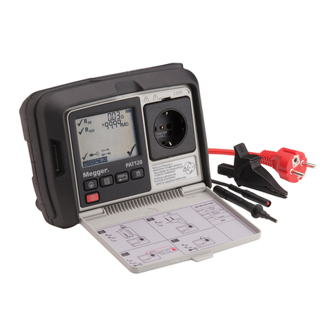
Megger
Megger PAT120 user guide

EXFO
EXFO FOT-10A instruction manual
PEWA
PEWA Amprobe LAN-1 user manual
