Chroma 69225 Series User manual


Get more information by downloading Chroma ATE Solutions APP
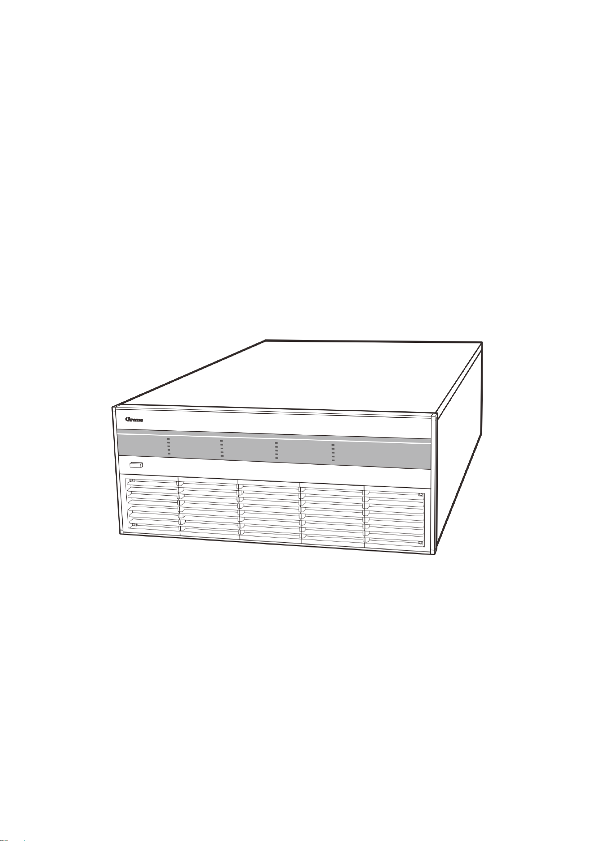
Regenerative Charge/Discharge Tester
69225/69212 Series
User’s Manual
Version 1.6
July 2019

ii
Legal Notices
The information in this document is subject to change without notice.
Chroma ATE INC. makes no warranty of any kind with regard to this manual, including, but
not limited to, the implied warranties of merchantability and fitness for a particular purpose.
Chroma ATE INC. shall not be held liable for errors contained herein or direct, indirect, special,
incidental or consequential damages in connection with the furnishing, performance, or use of
this material.
CHROMA ATE INC.
66 Huaya 1st Road, Guishan, Taoyuan 33383, Taiwan
Copyright Notices. Copyright 2015 Chroma ATE INC., all rights reserved. Reproduction,
adaptation, or translation of this document without prior written permission is prohibited,
except as allowed under the copyright laws.

iii
Warranty
All of Chroma’s instruments are warranted against defects in material and workmanship for a
period of one year from date of shipment. Chroma agrees to repair or replace any assembly
or component found to be defective, under normal use during this period. Chroma’s obligation
under this warranty is limited solely to repairing any such instrument, which in Chroma’s sole
opinion proves to be defective within the scope of the warranty when returned to the factory or
to an authorized service center. Purchaser is responsible for the shipping and cost of the
service item to Chroma factory or service center. Shipment should not be made without prior
authorization by Chroma.
This warranty does not apply to any products repaired or altered by persons not authorized by
Chroma, or not in accordance with instructions furnished by Chroma. If the instrument is
defective as a result of misuse, improper repair, or abnormal conditions or operations, repairs
will be billed at cost.
Chroma assumes no responsibility for its product being used in a hazardous or dangerous
manner either alone or in conjunction with other equipment. High voltage used in some
instruments may be dangerous if misused. Special disclaimers apply to these instruments.
Chroma assumes no liability for secondary charges or consequential damages and in any
event, Chroma’s liability for breach of warranty under any contract or otherwise, shall not
exceed the purchase price of the specific instrument shipped and against which a claim is
made.
Any recommendations made by Chroma regarding the use of its products are based upon
tests believed to be reliable; Chroma makes no warranty of the results to be obtained. This
warranty is in lieu of all other warranties, expressed or implied, and no representative or
person is authorized to represent or assume for Chroma any liability in connection with the
sale of our products other than set forth herein.
CHROMA ATE INC.
66 Huaya 1st Road, Guishan,
Taoyuan 33383, Taiwan
Tel: 886-3-327-9999
Fax: 886-3-327-8898
e-mail: [email protected]
http://www.chromaate.com

iv
Material Contents Declaration
The recycling label shown on the product indicates the Hazardous Substances contained in
the product as the table listed below.
: See <Table 1>.
: See <Table 2>.
<Table 1>
Part Name
Hazardous Substances
Lead
Mercury
Cadmium
Hexavalent
Chromium
Polybrominated
Biphenyls/
Polybromodiphenyl
Ethers
Hexabromocyclododecane/
Selected Phthalates
Group
Pb
Hg
Cd
Cr6+
PBB/PBDE
HBCDD/DEHP/BBP/DBP
PCBA O O O O O O
CHASSIS O O O O O O
ACCESSOR
Y
O O O O O O
PACKAGE O O O O O O
“O” indicates that the level of the specified chemical substance is less than the threshold level
specified in the standards of SJ/T
-11363-2006 and EU Directive 2011/65/EU.
“
” indicates that the level of the specified chemical substance exceeds the threshold level
specified in the standards of SJ/T
-11363-2006 and EU Directive 2011/65/EU.
Remarks:
The CE marking on product is a declaration of product compliance with EU
Directive 2011/65/EU.
Disposal
Do not dispose of electrical appliances as unsorted municipal waste, use separate collection
facilities. Contact your local government for information regarding the collection systems
available. If electrical appliances are disposed of in landfills or dumps, hazardous substances
can leak into the groundwater and get into the food chain, damaging your health and
well-being. When replacing old appliances with new one, the retailer is legally obligated to
take back your old appliances for disposal at least for free of charge.

v
<Table 2>
Part Name
Hazardous Substances
Lead
Mercury
Cadmium
Hexavalent
Chromium
Polybrominated
Biphenyls/
Polybromodiphenyl
Ethers
Hexabromocyclododecane/
Selected Phthalates
Group
Pb
Hg
Cd
Cr6+
PBB/PBDE
HBCDD/DEHP/BBP/DBP
PCBA O O O O O
CHASSIS O O O O O
ACCESSORY O O O O O
PACKAGE O O O O O O
“O” indicates that the level of the specified chemical substance is less than the threshold level
specified in the standards of SJ/T
-11363-2006 and EU Directive 2011/65/EU..
“
” indicates that the level of the specified chemical substance exceeds the threshold level
specified in the standar
ds of SJ/T-11363-2006 and EU Directive 2011/65/EU..
1.
Chroma is not fully transitioned to lead-free solder assembly at this moment; however,
most of the components used are RoHS compliant.
2.
The environment-friendly usage period of the product is assumed under the operating
environment specified in each product’s specification.
Disposal
Do not dispose of electrical appliances as unsorted municipal waste, use separate collection
facilities. Contact your local government for information regarding the collection systems
available. If electrical appliances are disposed of in landfills or dumps, hazardous substances
can leak into the groundwater and get into the food chain, damaging your health and
well-being. When replacing old appliances with new one, the retailer is legally obligated to
take back your old appliances for disposal at least for free of charge.
vi

vii
viii
This manual suits for next models
5
Table of contents
Other Chroma Test Equipment manuals

Chroma
Chroma 3300 User manual

Chroma
Chroma 19071 User manual

Chroma
Chroma 19020 User manual

Chroma
Chroma 63200 Series User manual

Chroma
Chroma 19071 User manual

Chroma
Chroma 63800 Series Owner's manual

Chroma
Chroma 63200A Series Owner's manual

Chroma
Chroma A195001 User manual

Chroma
Chroma 19572 User manual

Chroma
Chroma 19501-K User manual


