AGILE MODULATOR OPERATION
3. Agile Modulator Operation
The utilized modulators are high quality, vestigial sideband units with synthesized visual and aural carriers. The frequency
agile modulators allow front panel pushwheel switch selection of Standard, HRC or IRC Cable TV channels 2 through 135,
or VHF/UHF Broadcast TV channels 2 through 69. The Cable TV Channel Plan in use - Standard, HRC, or IRC – has to be
determined at time of ordering.
The heterodyne conversion system, in conjunction with the use of a SAW lter, ensures optimum vestigial selectivity for
adjacent channel operation.
The modulator is designed to accept any standard audio/video source such as NTSC video and audio baseband signals from
a satellite receiver, TV camera, videotape recorder, TV demodulator, Cable Set Top Box Converter, or similar signal source.
The modulator is designed to accept standard (negative sync) polarity video at nominal 1 V p-p level.
All level controls are located on the front panel for ease of operation.
The modulator’s maximum RF Output level at IVIS Output connector is +33 dBmV and is adjustable over a 10 dB range on
the modulator front panel by using RF Output Level control, and is adjustable an additional 20 dB by utilizing the common
front panel attenuator.
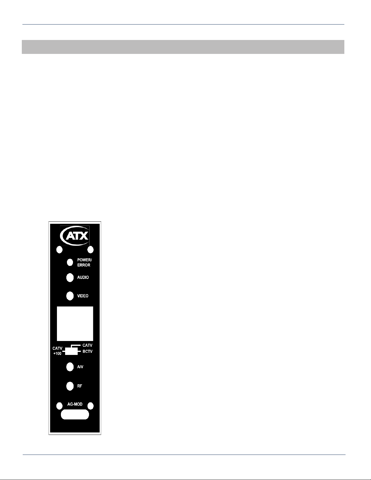
3.1. Agile Modulator Front Panel Controls
POWER/ERROR Indicator
Lights when the unit is powered. A ashing condition indicates an invalid channel setting or other
conditions that would cause the unit to operate on an invalid channel. The RF output is switched
OFF for ashing (ERROR) conditions.
AUDIO Level Control
The setting of this screwdriver adjustment determines the aural carrier deviation. Clockwise rotation
increases the carrier deviation.
VIDEO Level Control
The setting of this screwdriver adjustment determines the video modulation level. Clockwise rotation
increases the modulation depth.
Channel Number Switch
Sets the desired operating channel for Cable TV channels 2 through 135, or Broadcast TV channels
2 through 69.
Mode Switch
Sets the type of channel, Cable TV (CATV) or Broadcast TV (BCTV). The rst left position of the
switch (CATV +100) sets a leading “1” FOR Cable TV channels 100 through 135.
A/V Ratio Control
This screwdriver adjustment varies the level of the aural carrier over a range from 12 to 22 dB below
the visual carrier. The aural carrier should be adjusted to approximately 15 dB below the visual
carrier (normal operation). Clockwise rotation increases the aural carrier level.
RF Output Level
This screwdriver adjustment permits decreasing the RF output level a maximum of 10 dB as the
control is rotated counterclockwise.
CAUTION: USE AN INSULATED SCREWDRIVER BLADE WHEN ADJUSTING THE AUDIO,
VIDEO, A/V, OR RF ADJUSTMENTS. THIS WILL PREVENT THE POSSIBILITY OF SHORTING
CIRCUITRY TO THE FRONT PANEL IN THE EVENT THAT THE SCREWDRIVER SLIPS OUT OF
THE SLOT IN THE PLASTIC SHAFT OF THE POTENTIOMETER.
MDU Solutions®– IVIS Indoor Video Insertion System - Instalation & Operation Manual 3-1
CHAPTER 3: AGILE MODULATOR OPERATIONCHAPTER 2: INSTALLATION
Figure #2: Agile Modulator