CHAPTER 2: SYSTEM DESCRIPTION
2-2 MDU Solutions®– DVISf - Fiber Optic Digital Video Insertion System for Verizon FiOS®Networks – Installation & Operation Manual
For full capabilities see “DVISf Specications” on page 12-1
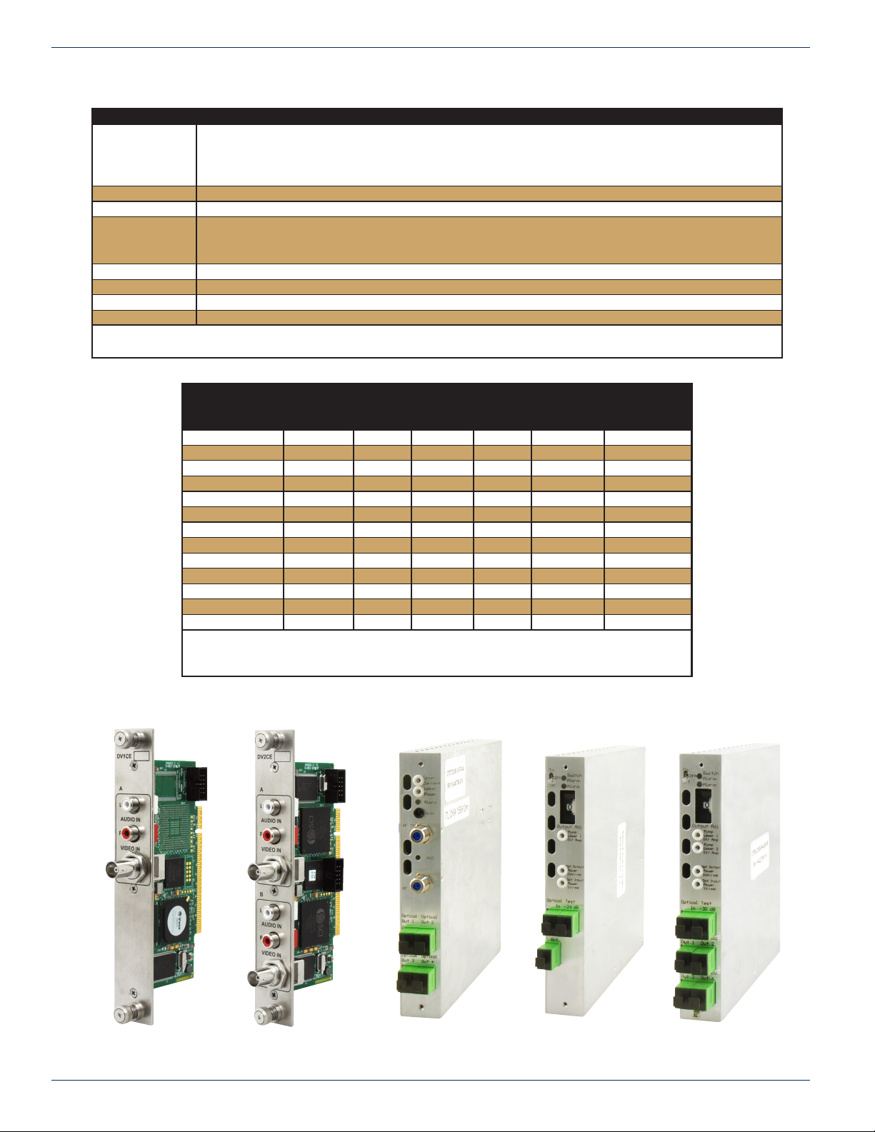
2.3 The DVISf Digital Audio/Video Insertion System
The DVISf device is a network-edge local content insertion device for digital video networks where distribution and insertion is
optical. It encodes local baseband analog content into a digital format for use in a property provisioned with digital only TVs,
STBs or DTAs and a cable system with PON architecture where analog spectrum is not available.
Target applications include:
• Security or surveillance camera feeds (MDUs, retirement homes)
• Text/character generator or local information channel (hotels, conference centers, gated communities)
• Distribution of ‘in-house’ or private channels throughout a cable system plant or property (e.g., sports stadiums,
network studios)
All deployments of digital signals in a modern cable TV system are presented with challenges which did not exist in the
former analog deployments. Specic challenges are faced when MDUs and institutions within the cable plant require locally
inserted content which must be received by the installed base of cable TV set top boxes (STB). The DVISf unit can be used in
these properties to encode local analog video cameras, message boards, instructional and advertising channels into MPEG2
streams and insert the content into a blank EIA channel or perform digital drop and insert into pre-existing QAM carriers. The
exible architecture of the DVISf product makes it an ideal candidate for any number of programs that an MDU or similar
property is likely to require.
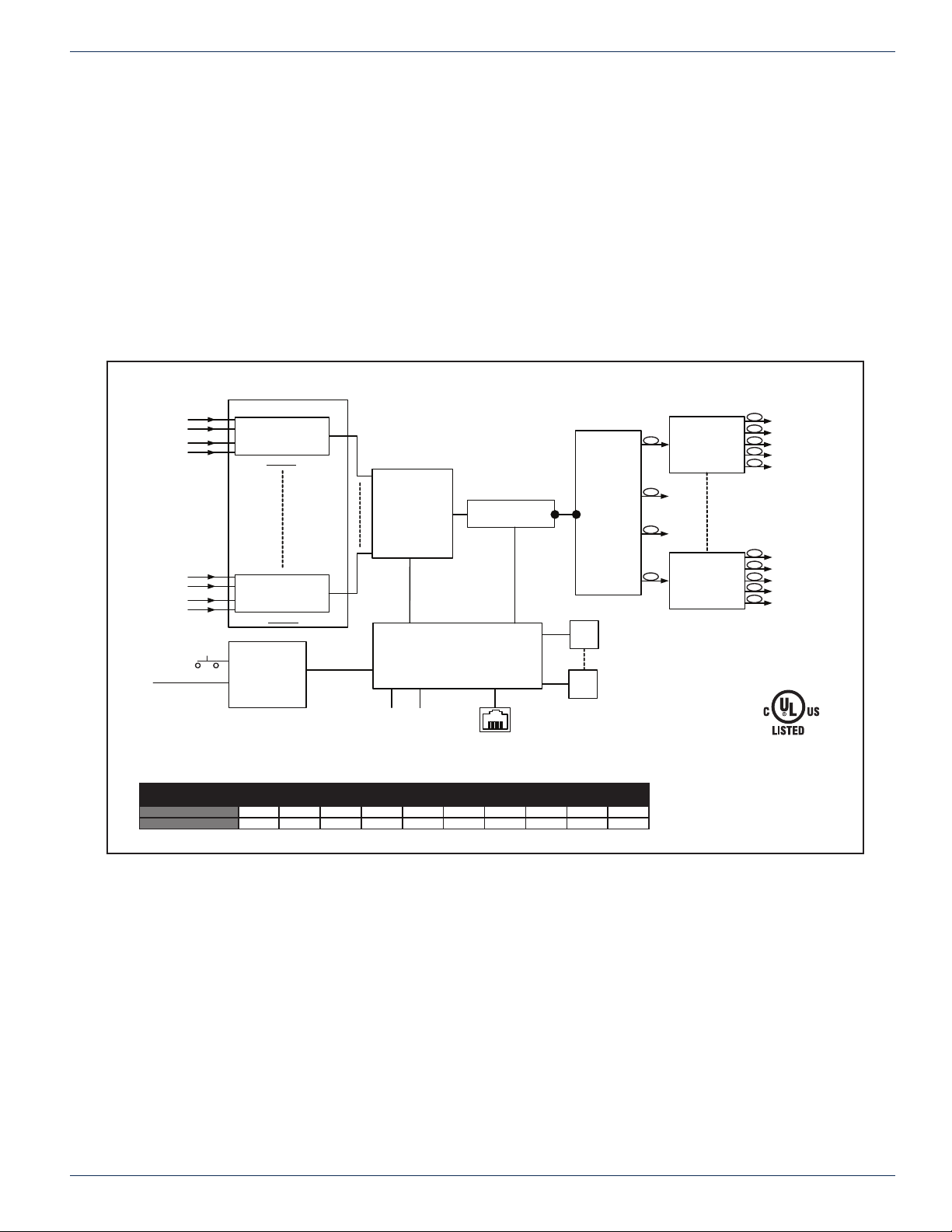
2.4 Optical Insertion Operation
The DVISf product supports installation into a PON topology. The equipment contains an integrated optical transmitter and up
to four EDFAs. The unit may be used to insert a single QAM channel into an optical network where the RF spectrum of the
target insertion channel has been left unoccupied. Optical channels from the broadcast transmitter and the DVISf narrow-cast
transmitter are combined using passive optical splitters. When the 1550 nm ITU band is received at the PON the DVISf QAM
channel will be present in an unoccupied EIA channel on the cable system. Availability of optical transmitters with a wide range
of ITU Grid channels allows placing the inserted optical carrier in relation to occupied 1550 nm spectrum.
2.5 Key Features
2.5.1 Flexible MPEG2 Digital Program Insertion
Designed for deployment in PON architectures, the DVISf product is capable of inserting digital programs into an EIA RF
channel where there is no pre-existing carrier on the broadcast Optical Network. The integrated QAM modulator is pre-set to
825 MHz for the Verizon PON Architecture.
2.5.2 Remote Monitoring Via SNMP
The DVISf product fully supports Simple Network Management Protocol (SNMP) which allows the monitoring of the built in
alarm points by a remote SNMP management console. The available DVISf MIB may be compiled into the remote Management
Console to provide notication of the triggering of any alarm either across a private network or the internet if available. Upon
triggering of a predened alarm, a trap is automatically sent by the unit to a listening SNMP management console.
The traps sent from the DVISf equipment are as follows:
• Internal Temperature beyond Threshold.
• Cooling Fan Failure.
• Video Status Changed (for each of up to 10 channels).
2.5.3 Simplied Mass Deployment and Backup with Conguration Export
The DVISf product allows the operator to export the programmed conguration as a le. The exported le may be used for
backup and archive purposes or to allow fast and easy deployment of multiple DVISf units with similar conguration. The le
may be imported to any number of units requiring similar settings, thus saving the time to manually program each unit before
deployment.
2.5.4 IPv4 Network Address Support
The DVISf unit uses IPv4 IP addressing and maybe congured with any valid IPv4 address to allow access from private
networks or from across the internet. For security against internet intrusion, the device forces assignment of a username and
password which may be changed at any time.