AU Tool CS520 User manual
AUTOOL CS520
Code Reader & OBD II Scanner
OK
I/M
CS 5 20
x
!
√
Trademark
AUTOOL Technology Co, Ltd. has registered its trademarks in
different countries, the trademark is .With regard to
the other trademark, service logo, domain, icon and company
name mentioned in this manual, they shall all belong to AUTOOL
and its other affiliated company, in other countries without the
registration yet of these trademark, service logo, domain name,
icon and company name of AUTOOL, here we announce they are
owned by AUTOOL. Any company or person shall not use the
trademark, service logo, domain name, icon and company name
of AUTOOL before getting approved by AUTOOL with written
certificates. Please visit our website www.autooltech.com or
email at [email protected] to contact us.
Safety Precautions and Warnings
To avoid personal injury or damage to vehicles and/or the
scanner, please read this instruction and the following safety
precautions at a minimum whenever testing a vehicle:
Test the vehicle in a well ventilated area: Exhaust gases are
poisonous.
Wear safety eye protection that meets ANSI standards.
Keep clothing, hair, hands, tools, test equipment, etc. away
from all moving or hot engine parts.
Block front of the drive wheels and never leave the vehicle
unattended while running tests.
Pay extreme attention when working around the ignition coil,
distributor cap, ignition wires and spark plugs. These
components create hazardous voltages when the engine is
running.
Put the transmission in PARK (for automatic transmission) or
NEUTRAL (for manual transmission) and make sure the
parking brake is engaged.
Keep a fire extinguisher suitable for gasoline/chemical/
electrical fires nearby.
Don’t connect or disconnect any test equipment while the
ignition is on or the engine is running.
Keep the scanner dry, clean, free from oil/water or grease. Use
a mild detergent on a clean cloth to clean the outside of the
scanner when necessary.
1 2
General Information
On-Board Diagnostics (OBD) II
The OBD II system is designed to monitor emission control
systems and key engine components by performing either
continuous or periodic tests of specific components and vehicle
conditions. When a problem is detected, the OBD II system turns
on a warning lamp (MIL) on the vehicle instrument panel to alert
the driver typically by the phrase of “Check Engine” or “Service
Engine Soon”. The system will also store important information
about the detected malfunction so that a technician can
accurately find and fix the problem.
Diagnostic Trouble Codes (DTCs)
OBD II Diagnostic Trouble Codes are codes that are stored by
the on-board computer diagnostic system in response to a
problem found in the vehicle. These codes identify a particular
problem area and are intended to provide you with a guide as to
where a fault might be occurring within a vehicle. OBD II
Diagnostic Trouble Codes consists of a five-digit alphanumeric
code. The first character, a letter, identifies which control system
sets the code. The other four characters, all numbers, provide
additional information on where the DTC originated and the
operating conditions that caused it to set.
OBD II Readiness Monitors
An important part of a vehicle’s OBD II system is the Readiness
Monitors, which are indicators used to find out if all of the
emissions components have been evaluated by the OBD II
system. They are running periodic tests on specific systems
and components to ensure that they are performing within
allowable limits.
Not all monitors are supported by all vehicles and the exact
number of monitors in any vehicle depends on the motor
vehicle manufacturer’s emissions control strategy.
Power-train Control Module (PCM) - OBD II terminology for
the on-board computer that controls engine and drive train.
Malfunction Indicator Light (MIL) - Malfunction Indicator Light
(Service Engine Soon, Check Engine) is a term used for the
light on the instrument panel.
DTC - Diagnostic Trouble Codes (DTC) that identify which
section of the emission control system has malfunctioned.
Enabling Criteria - Also termed Enabling Conditions. They are
the vehicle-specific events or conditions that must occur within
the engine before the various monitors will set, or run.
OBD II Drive Cycle - A specific mode of vehicle operation that
provides conditions required to set all the readiness monitors
applicable to the vehicle to the “ready” condition.
Freeze Frame Data - When an emissions related fault occurs,
the OBD II system sets a code, and records a snapshot of the
vehicle operating parameters to help in identifying the problem.
This set of value is Freeze Frame Data.
3 4
OBD II Definitions
OBD II Monitor Readiness Status
OBD II systems must indicate whether or not the vehicle’s PCM’s
monitor system has completed testing on each component. The
purpose of recording, readiness status is to allow inspectors to
determine if the vehicle’s OBD II system has tested all the
components and/or systems. Components that have been tested
will be reported as “Ready”, or “Complete”, meaning they have
been tested by the OBD II system.
OBD II Modes of Operation
Mode byte: The first byte in the stream is the mode number.
There are 10 modes for diagnostic requests. The first byte in
the response data bytes is this same number plus 64.
Mode $01 - Identifies the Powertrain information and
shows current data available to the scanner. This data
includes: DTC set, status of ob-board tests, and vehicle data
such as engine RPM, temperatures, ignition advance, speed,
air flow rates, and closed loop status for fuel system.

Mode $02 - Displays Freeze Frame data. Same data as in
mode 1, but is was captured and stored when a malfunction
occurred and a DTC was set. Some of the PIDs for mode one
are not implemented in this mode.
Mode $03 - Displays the type of powertrain or emission
related DTCs stored by a 5 digit code identifying the faults.
There may be more than one response message if there are
more trouble codes than will fit in the data bytes of the
response message, or if there are more than one ECU
computer responding.
Mode $04 - Used to clear DTCs and Freeze Frame Data.
This clears all diagnostic trouble codes that may be set
including freeze frame data and readiness monitors.
Mode $05 - Oxygen Sensor Test Results. This mode displays
the oxygen sensor monitor screen and the test results gathered
about the oxygen sensor.
Mode $06 - Non-continuously Monitored Systems test
results. There are typically a minimum value, a maximum
value, an a current value for each non-continuous monitor. This
data is optional, and it is defined by a given vehicle maker if it’s
used.
Mode $07 - Request for DTCs (pending) from Continuously
Monitored Systems after a single driving cycle has been
performed to determine if repair has fixed a problem. This
is used by service technicians to verify repair was performed
properly and after clearing diagnostic trouble codes.
Mode $08 - This special Control Mode requests control of
the on-board system, test, or component bi-directionally
(where applicable). This mode is manufacturer specific.
Mode $09 - Reports vehicle information. This information
includes vehicle VIN number and calibration information stored
in the vehicle ECUs.
Mode $0A - Request Emisson-Related Diagnostic Trouble
Codes with Permanent Status. This mode is required for all
emission-related DTCs. The presence of permanent DTCs at
an inspection without the MIL illuminated is an indication that a
proper repair was not verified by the on-board monitoring
system.
5 6
Location of the Data Link
Connector (DLC)
The DLC (Data Link Connector or Diagnostic Link Connector) is
the standardized 16-cavity connector where scanner interface
with the vehicle's on-board computer.

ESC BUTTON - Cancels a selection (or action) from a menu or
returns to the previous screen.
LEFT SCROLL BUTTON
HOME BUTTON - Back to the main menu.
UP SCROLL BUTTON - Moves up through menu and submenu
items in menu mode.
OK BUTTON - Confirms a selection (or action) from a menu.
RIGHT SCROLL BUTTON
DOWN SCROOL BUTTON - Moves down through menu and
submenu items in menu mode.
USB CONNECTOR - Connects the scanner to the PC for
printing or upgrading
7 8
Using the Scanner
Scanner Description
OBD II Connector - Connects the scanner with the vehicle’s
Data Link Connector (DLC).
LCD Display - Displays menus and test results.
(√ )Green LED - Indicates that engine systems are running
normally.
(!)Yellow LED - Indicates there is a possible problem. A
“Pending” DTC is present and/or some of the vehicle’s
emission monitors have not run their diagnostic testing.
× Red LED - Indicates there is a problem in one or more of the
vehicle’s system. The red LED is also used to show that DTCs
are present. DTCs are shown on the scanner display. In this
case, the MIL on the vehicle’s instrument panel will light steady
on.
I/M One-Click I/M Readiness Key - Quick-checks State
Emissions readiness and drive cycle verification.
The scanner is powered via the vehicle Data Link Connector
(DLC). Just plug OBD II connector of scanner to the vehicle’s
DLC.
Using the Scanner
Operating Temperature: 3 to 60 °C (32 to 140 °F)
Storage Temperature: -20 to 70°C (-14 to 158°F)
External Power: 8.0 to 18.0 V power provided via vehicle
battery
Accessories Included
The scan tool
USB cable
CD
Power
OK
I/M
CS 52 0
x
!
√
1
2
34
5
7
8
10
13
6
9
11
12
Unit of measure: Sets the unit of measure to English or Metric.
Beep: Turns on/off beep.
Device Self-Test: Checks if the LCD display, LED lamps and
keyboard are working normally.
910
When more than one vehicle control module is detected by the
scanner, you will be prompted to select the module where the
data may be retrieved.
CAUTION: Don’t connect or disconnect the scanner with ignition
on or engine running.
Help
The Help function allow viewing of some important information
such as tool information, information for OBD and Datastream.
Select Help from Main Screen.
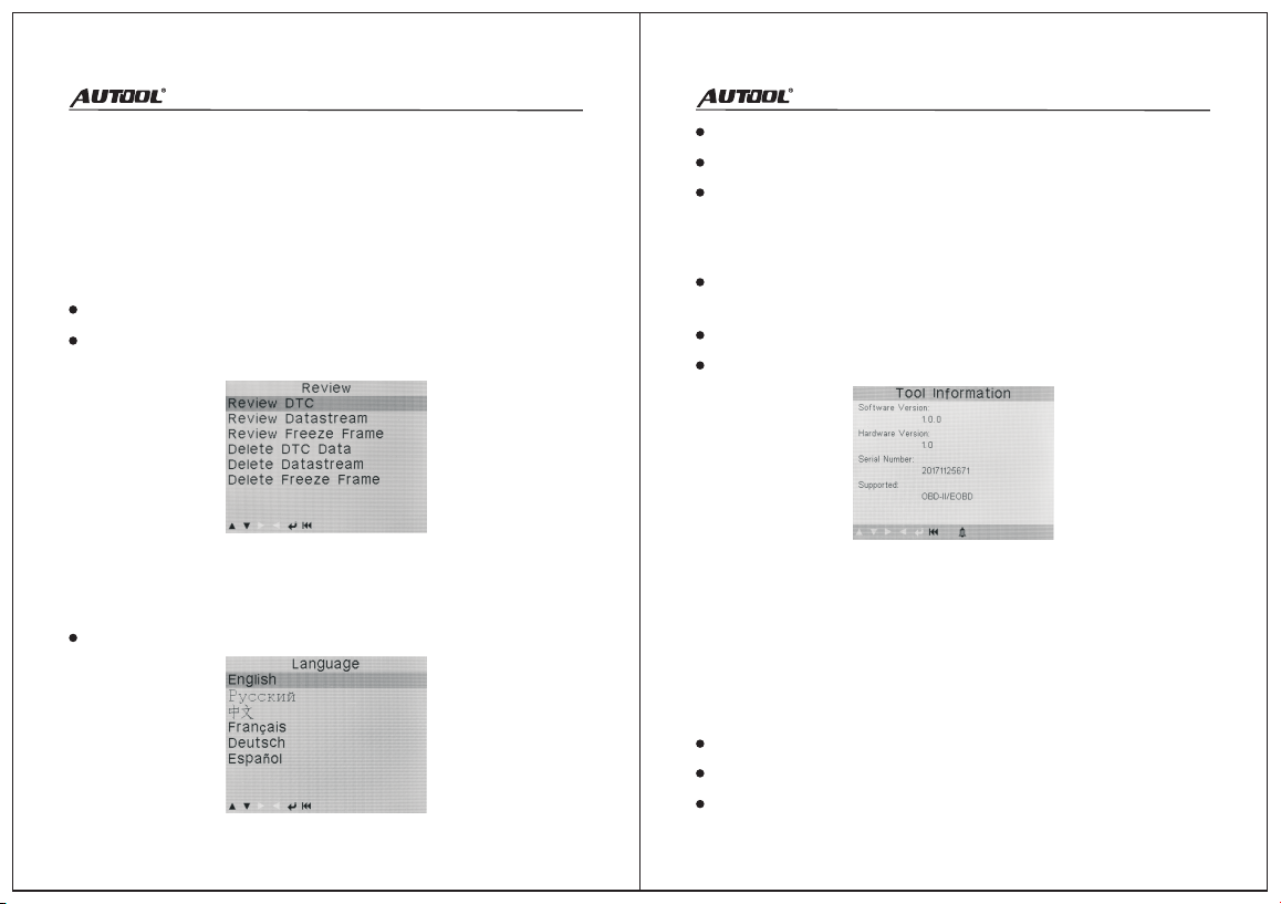
View Tool Information in Help menu.
OBD II Diagnostics
The DTC Lookup function is used to search for definitions of
DTCs stored in the DTC library and for code breaker information.
DTC Lookup
The Review function allows viewing of data from last test
recorded by the scanner.
Review
Select Review from Main Screen.
Use the UP/DOWN scroll button to select the desired item from
Review menu, and press the OK button.
The scanner allows you to make the following adjustments and
settings:
Tool Setup
Languages: Selects the desired language.
Turn the ignition off.
Connect OBD II connector of scanner to the vehicle’s DLC.
Turn the ignition on. Engine can be off or running.
Permanent DTC shall be stored in non-volatile memory and
may not be cleared by any diagnostic services or by
disconnecting power to ECU.
11 12
Erasing Code can be done with the key on enginne off (KOEO).
Do not start the engine.
Help
Turn on the scan tool. Select Diagnose from the Main Screen.
Press the OK button to wait for the menu to appear. Once the
vehicle protocol is detected, messages displaying OBD II
protocols will be observed.
If the scan tool fails to communicate with the vehicle’s ECU
more than three times, a “Communication Error” message
shows up on the display.
Check if the scanner’s OBD II connector is connected to the
vehicle’s DLC.
Verify that the ignition is ON.
Verify that the vehicle is OBD II compliant.
Reading Codes
Reading Codes can be done with the key on enginee off
(KOEO) or with the key on engine running (KOER)
Stored Codes are also known as “hard codes”, which are
fault/trouble codes that have been stored in the vehicle
computer memory. The Stored Codes will cause the control
module to illuminate the MIL when emission-related fault
occurs.
Pending Codes are also referred to as “maturing codes” or
“continuous monitor codes”. They will not turn on the MIL. If
the fault does not occur within a certain number of warm-up
cycles, the code clears from memory.
Permanent Codes are DTCs that are “confirmed” and are
retained in the non-volatile memory of the computer.
Erasing DTCs may allow the scanner to delete not only the
codes from the vehicle’s on-board computer, but also “Freeze
Frame” data and manufacturer specific enhanced data.
Moreover, the I/M Readiness Monitor Status for all vehicle
monitors is reset to Not Ready or Not Complete status. Do not
clear the codes before the system has been checked
completely by a technician.
Erasing codes does not mean that trouble codes in ECU have
been eliminated completely. As long as there is fault with the
vehicle, the trouble codes keep on presenting.
NOTE:
I/M readiness function is used to check the operations of the
Emission System on OBD II compliant vehicles.
An I/M Readiness Status result of “NO” does not necessarily
indicate that the vehicle being tested will fail the state I/M
inspection. For some states, one or more such monitors may be
allowed to be “Not Ready” to pass the emissions inspection.
I/M Readiness
The Data Stream function allows viewing of live or real time PID
data of vehicle’s computer modules(s).
Data Stream
13 14
The Vehicle Information function enables retrieval of VIN, CINs,
CVNS and In-use Performance Tracking on 2000 and newer
vehicles that support Mode 9.
Vehicle Information
The Print Data function allows printing out diagnostic data
recorded by the scanner or customized test reports.
Print Data
Freeze Frame allows the technician to view the vehicle’s
operating parameters when a DTC is detected. It will help the
technician by allowing the parameters to be duplicated for
diagnosis and repair.
Freeze Frame
OBD II regulations set by SAE require that relevant vehicles
monitor and tests on the oxygen (O2) sensors to identify
problems related to fuel efficiency and vehicle emissions.
The O2 Sensor Test function allows retrieval and viewing of O2
sensor monitor test results for the most latest performed testes
from the vehicle’s on-board computer.
The O2 Sensor Test function is not supported by vehicles which
communicate using CAN.
O2 Sensor Test
The On-Board Monitoring for non-CAN equipped vehicles
retrieves and displays test results for emission-related power train
components and systems that are not continuously monitored.
The On-Board Monitoring for CAN-equipped vehicles retrieves
and displays test results for emission-related power train
components and systems that are and are not continuously
monitored.
On-Boarding Monitoring
The EVAP System function allows initiating a leak test for the
vehicle’s EVAP system. The scanner commands the vehicle’s on-
board computer to start the leak test.
EVAP System (Mode $8)
Connect the scan tool to computer with the USB cable
provided.
Run the update Tool Kit in your computer.
Select Print Data from the scanner Main Menu.
Select the desired item to print from Print Data menu.
If you want to print all retrieved data, select Print All Data from
Print Data menu.
Warranty Ser vice
There are 3 years' warranty for AUTOOL product main unit and
1 year warranty for the accessories since the day the customers
have received the product parcel.
Repair or replace the equipment will be done according to the
specific fault conditions;
We guarantee that all replacement parts, accessories or
equipment are brand new;
When there is a product breakdown that can not be solved
within 90 days, customer should provide video and pictures as
Warranty Access
proof, we will bear the freight cost and provide customer the
accessories in need to replace. After receiving the product for
more than 90 days, the customer shall bear the freight cost,
we will provide the accessory for free to replace.
Product is bought through non-official AUTOOL purchase
channel.
Product failure is caused by incorrect use of the product, use
for other wrong purpose or human factors.
Warranty Access
Disclaimer: The AUTOOL Technology Co, Ltd. reserves the right
to change product designs and specifications without prior notice.
The physical appearance and color may differ from those shown
in the instruction manual. Please refer to the actual product. If
you have any question, please contact the dealer or the Autool
service center. The company have the final explanation right of
product and shall not bear any consequences due to
misunderstanding.
15 16
Table of contents
Other AU Tool Diagnostic Equipment manuals


