Stardex INJECTION EXPLORER User manual

INJECTION EXPLORER
STARDEX™ 0501

1. Security information
Read the instructions carefully before using Stardex 0501 (the device).
The device must be connected only to AC 220V with cable from the delivery kit.
Getting of electrical charges on the equipment is strictly prohibited!
Getting liquids inside the device is strictly prohibited!
Device body is constructed to protect its components from mechanical impact while
operating. Avoid body and front panel damage, do not drop the device and do not put
heavy objects on the top of it.
In case of defect (smoke, sparks, specific smell) immediately unplug it and send to the
service center.
All cables from the delivery kit must be supplied with standard plugs and do not have
mechanical damage.
The device does not contain self repairable parts inside. It is strictly prohibited to open the
device.
Keep and use the device in the areas inaccessible to children and pets.
The device is designed to work with Common Rail system. The user must understand
structure and working principle of injection systems.
Incorrect use of the device may cause the damage of the device or user’s injury.
2. Technical requirements and operation directions
Dimensions 230 mm х290 mm х60mm
AC power supply 220V 50Hz
Power consumption 50 W
Operating temperature from -100Сto + 500С
Relative humidity no more than 90% at 250С

Injection sensor
connector
Universal cable
connector
Power supply
connector
3. General Description
STARDEX 0501 is a highly professional universal device for the relative exploration of the
injection characteristics in Common Rail diesel systems and UIS. The device allows making
high precise measurements and registers the delay time of injection (the difference in time
between the moment of getting the electric pulse to the injector and the beginning of
injection) with output parameters on the colored touch screen display in digital and
graphical form. The results of measurements are saved in the device memory that allows
making a comparative analysis of the characteristics of all injectors mounted on the engine,
and making the necessary adjustments.
4. Switching on/off the device, connectors
1) Connect power supply unit connector to the appropriate connector of the device and
plug it in AC 220 V 50 Hz outlet.
2) Connect universal cable to the appropriate connector and connect it to the signal
wires of the injector using the appropriate cap.
3) Install the injection sensor into the appropriate adapter and install it into the fuel line
as close as possible to the nozzle (the best solution is to install the adapter with
injection sensor directly to the nozzle) and connect injection sensor into the
appropriate connector of the device.
4) To switch off the device unplug the power supply unit from the AC outlet.
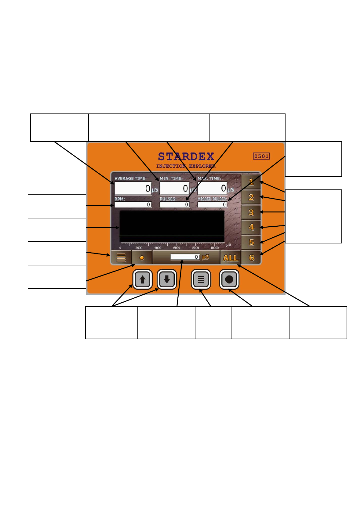
Average delay
time
Minimal delay
time
Maximal delay
time
Accomplished
injection counter
Missed
injection
counter
RPM
Injection
diagram
Navigation
buttons
“Menu”
button
“Reset” button
Interactive
button “Menu”
Interactive
button “Reset”
Interactive
button “All”
Interactive
buttons of
injectors
selection
Delay time on
the graph
5. Interface description and control buttons
Main window
RPM - the number of injections per minute, equal to the revolutions of the CamBox shaft, if
UIS is tested.
Average delay time –average parameter of injection delay time.
Minimal delay time –minimal registered injection delay time.
Maximal delay time –maximal registered injection delay time.
Accomplished injection counter –the number of signals to the injector after which the
injection from the nozzle was registered by the injection sensor.

Missed injection counter –the number of signals to the injector after which the injection
from the nozzle was not registered.
Injection diagram –graphic representation of the injection process registered by injection
sensor. The graph is updated when you click on the Reset button or touch the graph image
area on the screen.
Delay time on the graph –delay time of injection for a particular graph displayed on the
screen.
Reset button –resets all the parameters to the origin and the previous results are not
saved.
Menu button –switches on the device menu. Also the Menu button takes you back to the
main window of the device from the menu or exit from the submenu to the menu with
saving all the made changes.
Navigation buttons –are used for navigation in the menu and also to move between
different results of injectors testing or to display a comparative exploration of all tested
injectors on the screen.
Interactive buttons of injector selection –numbered interactive buttons according to the
order of testing the injectors. They are also used to switch between the results of injectors
testing. Exploration results of each injector are saved in the memory until the device is
unplugged.
Interactive button “All”–opens the statistics window for all tested injectors.
Interactive buttons “Menu” and “Reset” mean the same as “Menu” and “Reset” buttons
on the front panel.
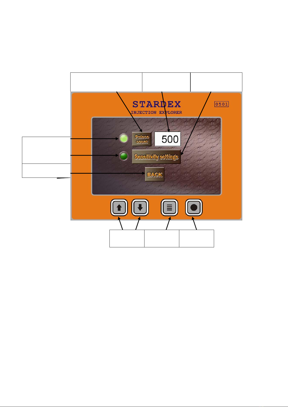
Menu window
Pulses count button –pulses counter changes the number of measurements values
(500, 1000, 2000)
Number of measurements –the number of accomplished injections after which delay
time counting will be finished.
Markers of keyboard control –are used for backlight of the selected menu item.
Navigation buttons –are used for selection of menu items.
Exit button –exits to the main window with saving all the made changes.
Enter button –is used for activation of the selected menu item.
Sensitivity settings button –opens the window of sensitivity settings.
Pulses count button
Number of
measurements
Markers of
keyboard control
Sensitivity settings
button
Exit button
Navigation
buttons
Exit button
Enter
button
Sensitivity
settings
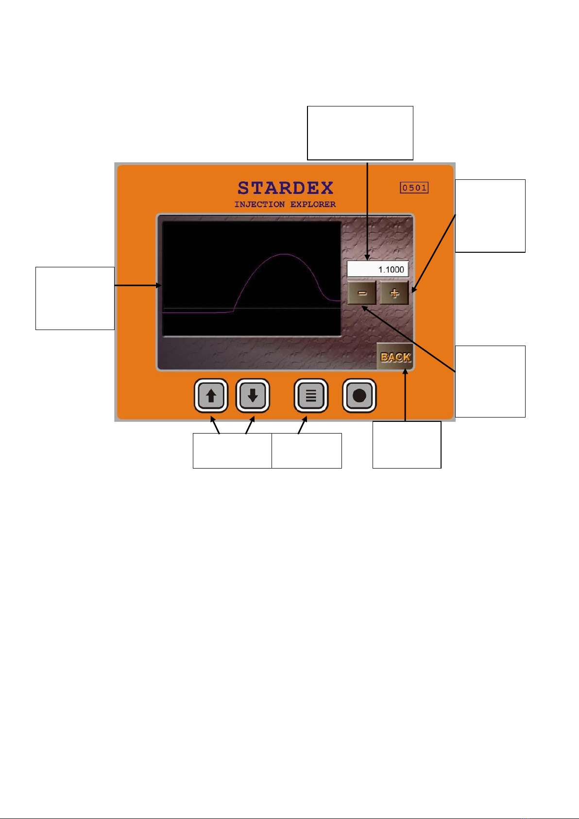
gragh
Sensitivity
threshold
Decrease
sensitivity
threshold
button
Increase
sensitivity
threshold
button
Exit button
Navigation
buttons
Exit button
Sensitivity settings window
Sensitivity threshold –with the increase of sensitivity threshold the sensor receptivity
to the small fuel supply decreases and vice versa. It is recommended to change the
sensitivity threshold only in case of delay time measurements of very small or very large
fuel delivery modes.
Sensitivity settings graph –the curve on the graph schematically shows the level of
injection sensor signal and the horizontal line shows the threshold of sensitivity.
Injection is fixed at the point where the injection sensor signal crosses the threshold of
sensitivity. It is recommended to set the sensitivity threshold in such a way that it will
cross the curve of injection sensor level as low as possible (watch example). The curve of
sensor signal injection level corresponds to the curve of the last injection measured in
the main window.
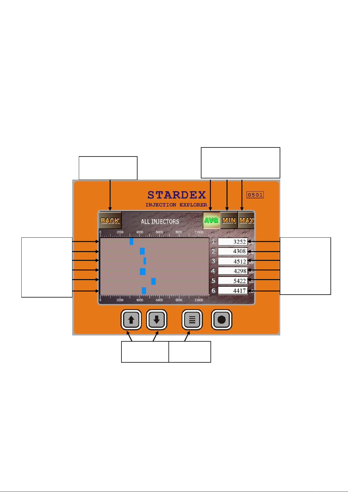
Numeral
values of
injection delay
Type selection buttons of
the injection delay
Values
diagrams of
injection delay
for each
injector
Exit button
Navigation
buttons
Exit button
Decrease sensitivity threshold button –decreases the sensitivity threshold of injection
sensor.
Increase sensitivity threshold button –increases the sensitivity threshold of injection
sensor.
Navigation buttons –change the sensitivity threshold (more\less).
Exit button –saves all changes made in the sensitivity settings window and exits to the
menu window.
Statistics window for all tested injectors
Numeral values of injection delay –numeral displaying of injection delay for a particular
injector.
Type selection buttons of the injection delay–AVG, MIN, MAX buttons change the type of
the displayed parameters in the area of numeral values of injection delay (average, minimal
and maximal).
Values diagrams of injection delay for each injector –graphic display of all delay time
values for all tested injectors.
Navigation buttons –changes the type of displaying values of injection delay AVG, MIN,
MAX (average, minimal and maximal).
Exit button –exits to the main menu.
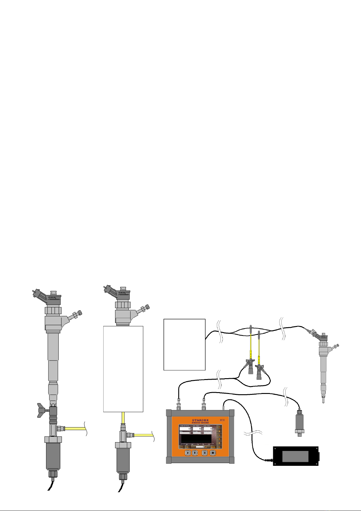
6. Installation on the test bench and the beginning of work.
Switch on the device. Install injection sensor into the adaptor. Install this adaptor directly
on the nozzle of the injector or in the fuel line as close as possible to the nozzle. Connect
the universal cable of the device to signal wires of the injector using universal adapter or
probe so that the signal from the pulse simulator to the injectors comes both on the
injector and on the device. Start the injector testing on the test bench. Wait about a minute
to fill the fuel line. To start the injection delay measurement, choose the number of injector
and press the button “Reset”. When the accomplished injection counter reaches the
number of measurements indicated in the menu window, the counting of all parameters
will be stopped and the results will be saved (it is possible to re-view the results of injectors
testing by clicking the button with the number of required injector in the main window or
open the statistics window for all the tested injectors).
Connection pattern.
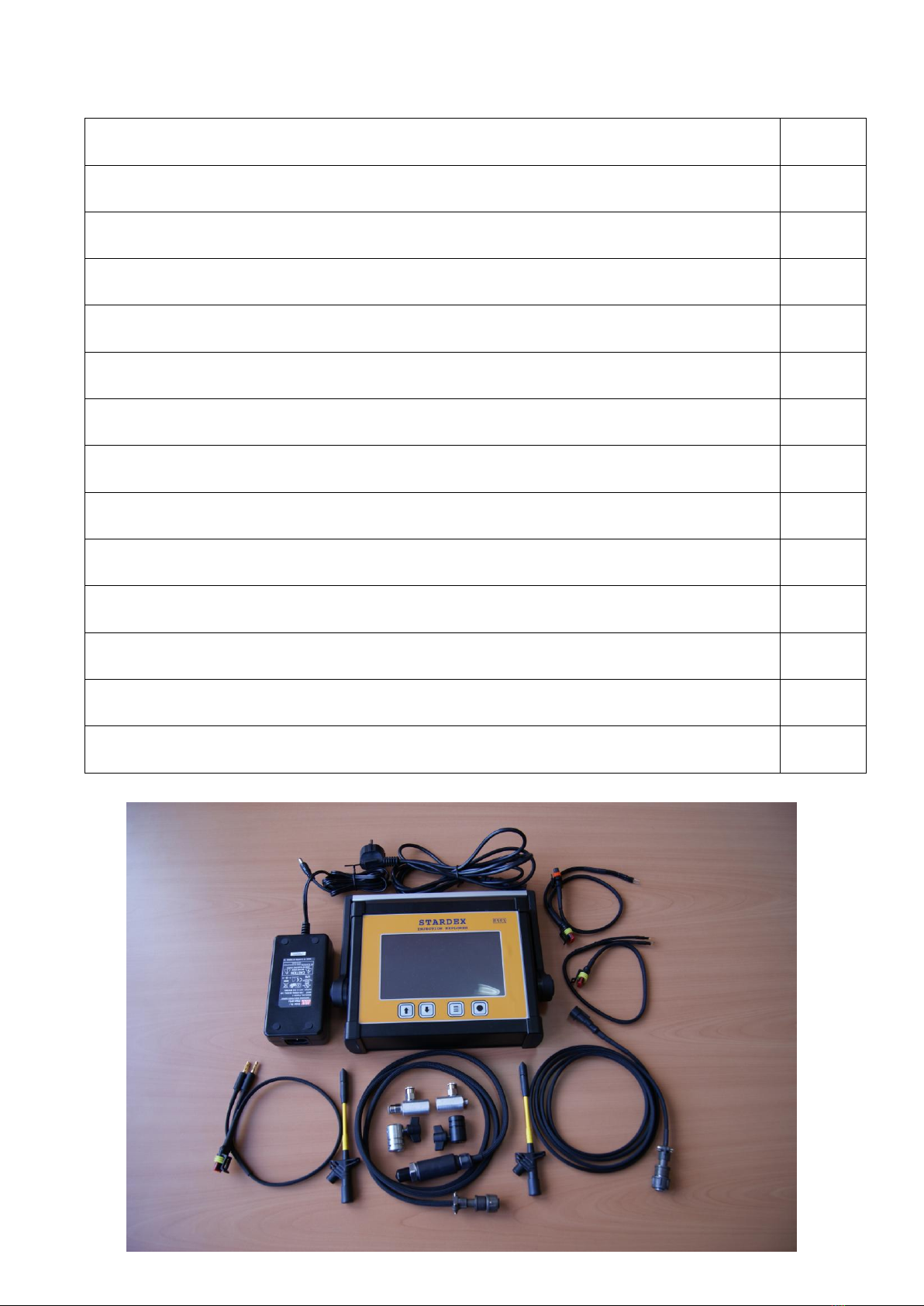
7. Delivery kit
Stardex 0501
1 pc.
Power unit
1 pc.
Power cable
1 pc.
Universal cable
1 pc.
Universal cable adaptor # 1
1 pc.
Universal cable adaptor # 2
1 pc.
Universal cable adaptor # 3
1 pc.
Probes for getting the signal from injector cables
2 pc.
Injection sensor
1 pc.
Fuel disperser d 7 mm
1 pc.
Fuel disperser d 9 mm
1 pc.
Adaptor #1
1 pc.
Adaptor #2
1 pc.
Technical description
1 pc.

8. Warranty and technical support.
The equipment has 2 year warranty. The manufacturer is not responsible for the damage
due to violation of the operation terms, misuse including unskillful or mistaken personnel
actions and if there are traces of mechanical impact.
9. Package.
The product is packed into bubble wrap and carton box.
Manufactured by:
STARDEX OY
PULTTITIE 2
00880 HELSINKI
FINLAND
www.stardex.fi
This manual suits for next models
1
Table of contents


