Thinkcar THINKOBD 500 User manual

EN
THINKOBD 500

EN Safety Precautions and Warnings
To avoid personal injury, property loss, or accidental damage to the product, read all of the
information in this section before using the product.
Data and Software Protection
Do not delete unknown les or change the names of les or directories created by others,
otherwise the device software may not run.
Do not disassemble or modify the equipment
The device is a sealed device with no user-serviceable parts inside. All internal repairs must
be performed by an authorized maintenance organization or qualied technician. Attempts to
disassemble or modify the device will void the warranty.
Data and Software Protection
Do not delete unknown files or change the names of files or directories created by others,
otherwise the device software may not run.
Note: Access to network resources makes the device vulnerable to computer viruses, hackers, spyware,
and other malicious behaviors, and may damage the device, software, or data. To make ensure that you
are using rewalls, anti-virus software and anti-spyware software to provide adequate protection for
your computer and keep these software up to date.
IC Requirement
This device contains licence-exempt transmitter(s)/receiver(s) that comply with
Innovation,Science and Economic Development Canada’ s licence-exempt RSS(s).
Operation is subject to the following two conditions:
(1)This device may not cause interference.
(2)This device must accept any interference,including interference that may cause
undesired operation of the device.
L'émetteur/récepteur exempt de licence contenu dans le présent appareil est conforme
aux CNR d'Innovation,Sciences et Développement économique Canada applicables
aux appareils radio exempts de licence. L 'exploitation est autorisée aux deux conditions
suivantes :
1)L'appareil ne doit pas produire de brouillage;
2)L'appareil doit accepter tout brouillage radioélectrique subi, même si le brouillage est
susceptible d'en compromettre le fonctionnement.
IC WARNING
Cet équipement est conforme aux limites d’exposition aux rayonnements ISED établies
pour un environnement non contrôlé. L’utilisateur nal doit suivre les instructions
spéciques pour satisfaire les normes. Cet émetteur ne doit pas être co-implanté ou
fonctionner en conjonction avec toute autre antenne ou transmetteur.
Le dispositif portatif est conçu pour répondre aux exigences d’exposition aux ondes radio
établie par ledéveloppement énergétique DURABLE. Ces exigences un SAR limite de 1,6
W/kg en moyenne pour un gramme de tissu. La valeur SAR la 0.733W/kg plus élevée
signalée en vertu de cette norme lors de la certication de produit à utiliser lorsqu’il est
correctement porté sur le corps.

EN
FCC Requirement
Changes or modications not expressly approved by the party responsible for
compliance could void the user’ s authority to operate the equipment.
This device complies with Part 15 of the FCC Rules. Operation is subject to the following
two conditions:
(1) this device may not cause harmful interference, and
(2) this device must accept any interference received, including interference that may
cause undesired operation.
Note: This equipment has been tested and found to comply with the limits for a Class
B digital device, pursuant to Part 15 of the FCC Rules. These limits are designed to
provide reasonable protection against harmful interference in a residential installation.
This equipment generates, uses, and can radiate radio frequency energy, and if not
installed and used in accordance with the instructions, may cause harmful interference
to radio communications. However, there is no guarantee that interference will not occur
in a particular installation. If this equipment does cause harmful interference to radio
or television reception, which can be determined by turning the equipment o and on,
the user is encouraged to try to correct the interference by one or more of the following
measures:
– Reorient or relocate the receiving antenna.
– Increase the separation between the equipment and receiver.
– Connect the equipment into an outlet on a circuit dierent from that to which the
receiver is connected.
– Consult the dealer or an experienced radio/TV technician for help.
FCC WARNING
This equipment complies with FCC radiation exposure limits set forth for an uncontrolled
environment. End user must follow the specic operating instructions for satisfying RF
exposure compliance. This transmitter must not be co-located or operating in conjunction
with any other antenna or transmitter.
The mobile device is designed to meet the requirements for exposure to radio waves
established by the Federal Communications Commission (USA). These requirements
set a SAR limit of 1.6 W/kg averaged over one gram of tissue. The highest SAR value
reported under this standard during product certication for use when properly worn on
the body is 0.733 W/kg.
For body operation, this device has been tested and meets FCC RF exposure guidelines
when used with any accessory that contains no metal and that positions a minimum of
15mm from the body. Use of other accessories may not ensure compliance with FCC RF
exposure guidelines.

EN 1. Product Descriptions
1
2
4
7
6
3
5
8
9
(1) Diagnostic Cable: Standard OBDII diagnostic cable
(2) LCD Display: 2.8 inch display (240*320)
(3) Code severity alert: Three status indicators
(4) I/M Button: Quickly enter "I/M READINESS" to view the data ow
(5) Help: About OBD instructions, about data ow instructions, about printing instructions, about
exhaust ready instructions
(6) Up, down, left and right keys: used to select interactive functions
(7) Return key: Return to upper function
(8) OK Return: Conrm button
(9) Mini usb: Used to upgrade software and print functions
Code severity alert
Code severity reminder: By reading the code, you can quickly determine whether your vehicle
needs to be repaired immediately, or whether you can wait for you to go home and repair it
yourself.
LED indicator warning: There are three LED indicators on the barcode reader: NO DTC: Your
vehicle is in good condition. Pending DTC: You need to solve the problem and clear the code.
Permanent DTC: There is a serious problem with your vehicle. If these problems cannot be
resolved, you may fail the emission test.

EN
Technical Specications
Display: 2.8 inch display
Working Environment: 0 to 50℃(32 to 122℉)
Storage Environment: -20 to 60℃(-4 to 140℉)
Power Supply: 9-18V vehicle power
Supported Protocols: ISO9141, KWP2000 (ISO 14230), J1850PWM,J1850VPM and CAN
OBDII protocol
Function Description
1. Compatible with vehicles after 1966 and vehicles with updated OBDII protocol
2. Read & clear DTCS, check and turn o engine light
3. Live data stream in graph for an eective troubleshooting
4. O2 sensor, on-board monitor & EVAP system for emission inspection
5. Built-in DTC lookup library, no need to search for DTC denitions
6. View VIN, CID and CVN, quickly read vehicle identication
7. Supports 8 Languages including English, French, Spanish, German, Russian,
Japanese, Italian and Portuguese
8. Prints diagnostic data report immediately for your inspection
9. Compatible with ISO9141, KWP2000, J1850PWM, J1850VWM, J1850VPW and can
OBD II protocol
2. How To Use
2.1 Data Link Connector (DLC) Location
The DLC (Data Link Connector or Diagnostic Link Connector) is typically a 16pin connector
where diagnostic code readers interface with the vehicle’s onboard computer. The DLC is
usually located 12 inches from the center of the instrument panel (dash), under or around the
driver’s side for most vehicles. If Data Link Connector is not located under dashboard, a label
should be there telling location. For some Asian and European vehicles, the DLC is located
behind the ashtray and the ashtray must be removed to access the connector. If the DLC cannot
be found, refer to the vehicle’s service manual for the location.
Note: Turn on the ignition of the vehicle, the voltage range of the device should be 9-18V, and
the throttle should be in the closed position.
EN 2.2 Application Overview
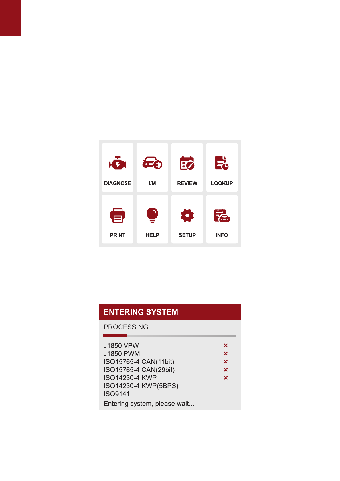
When the code reader boots up, the Home screen opens. This screen shows all applications
loaded on the unit. Following applications are preloaded into the code reader:
● Diagnostics : leads to OBDII screens for all 9 generic OBD system tests.
● IM Readiness:option allows to view a snapshot of the operations for the emission system on
OBDII/EOBD vehicles.
● Lookup : leads to screens for diagnostic trouble code lookup.
● Review Data : leads to screens for access to tested data les.
● Print : leads to screens for access to printing function
● Help : You will nd the device OBD function and system instructions
● Setup :leads to screens for adjusting default settings to meet your own preference when using
the code reader.
● Info : leads to screen that shows information about the code reader.
Note: Not all function options of the protocol listed in this device are applicable to all vehicles. The
available options may vary depending on the year, model, and make of the vehicle tested. If this option
is not applicable to the vehicle under test, "X" will be displayed. When the barcode reader is connected
to the vehicle, it will automatically check the status of the I/M monitor and give a summary report on
the display, as shown in the gure below.
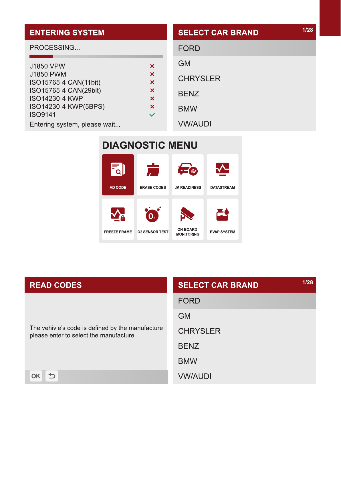
1.1.1 Select "Diagnosis", click "OK" to enter the system diagnosis, select the vehicle
type, and enter the diagnosis function list.
EN
1.1.2 Select "READ CODE" and click "OK" to select vehicle type to view DTC diagnostic
data.

EN
1.2 Select "ERASE CODES" to clear the fault code
Note: Erase Codes menu lets you to clear all current and stored DTCs from the control module.
Also it erases all temporary ECU information, including freeze frame. So make sure that the
selected system are completely checked and serviced by technicians and no vital information
will be lost before clearing codes.
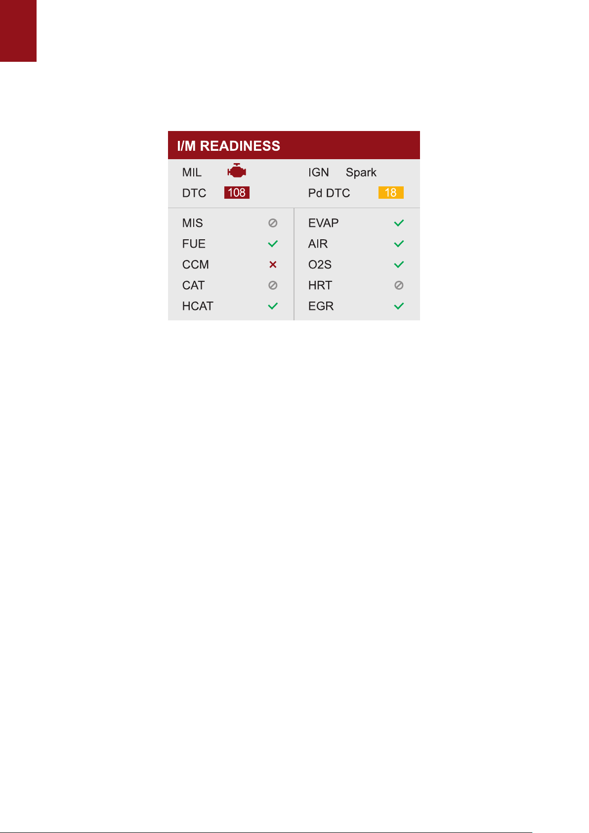
1.3 Select” I/M READINESS” and click "OK" to view the I/M data ow.
EN
NOTE :
● To review I/M Readiness status, make sure that the ignition key is switched to ON with the engine o.
● Not all monitors are supported by all vehicles.
I/M Readiness is a useful function used to check if all monitors are OK or N/A. The vehicle’s
computer performs tests on the emission system during normal driving conditions. After a
specic amount of drive time (each monitor has specic driving conditions and time required),
the computer’s monitors decide if the vehicles emission system is working correctly. When the
monitor’s status is:
● OK - vehicle was driven enough to complete the monitor.
● INC (Incomplete) - vehicle was not driven enough to complete the monitor.
● N/A (Not Applicable) - vehicle does not support that monitor. There are two types of I/M
Readiness tests:
● Since DTCs Cleared - shows status of the monitors since the DTCs were last cleared.
● This Drive Cycle - shows status of monitors since the start of the current drive cycle. Below is
a list of abbreviations and names of OBD II monitors supported by the code reader.
There are two ways to retrieve I/M Readiness Status data:
● One-click I/M readiness key
● Typical way: select I/M Readiness from Diagnostic Menu
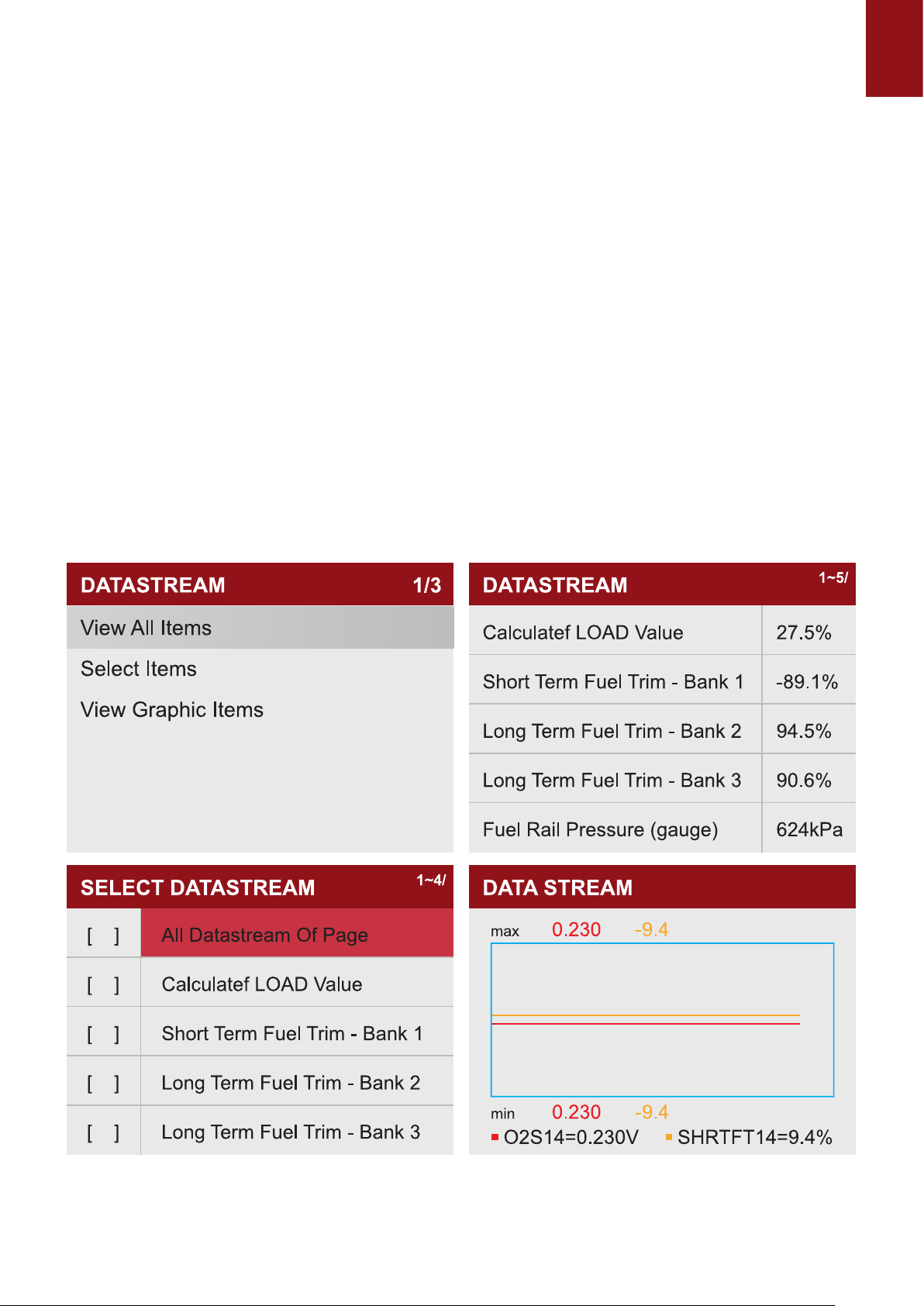
1.4 Select "DATA STREAM" View all data streams,Next click "OK", and nally you can view the
graphics data ow.
Tips: Use the BACK key to return to diagnostic menu.
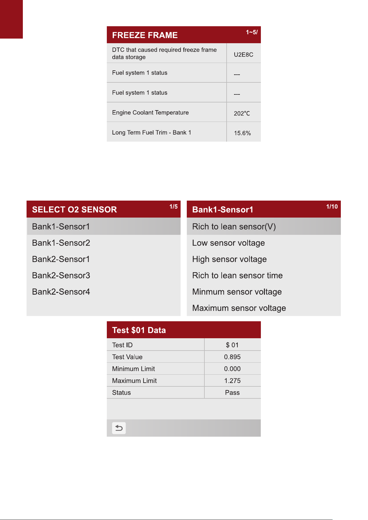
1.5 Select "FREEZE FRAME" and click "OK" to view the freeze frame data stream.
EN
Freeze Frame menu displays freeze frame data, a snapshot of critical vehicle operating
conditions automatically recorded by the on-board computer at the time of the DTC set. It is a
good function to help determine what caused the fault.
1.6 Select "O2 SENSOR TEST" and click "OK" to view O2 Sensor data Stream.
OBD II regulations require certain vehicles monitor and test oxygen (O2) sensors to isolate fuel
and emissions related faults. The O2 Monitor Test function is used to retrieve completed O2
sensors monitor test results.
The O2 Monitor Test is not an on-demand test. O2 sensors are not tested when selected via the
menu but tested when engine operating conditions are within specied limits.
EN
Tips: Dierent car models have detected dierent numbers of oxygen sensors, please check according
to the required sensors.
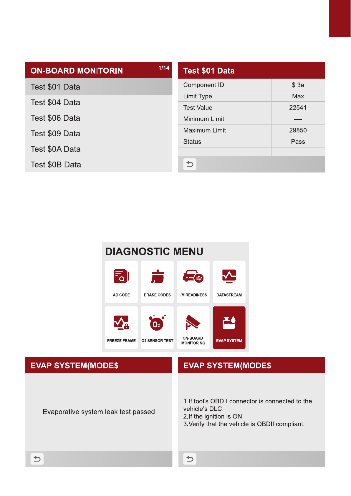
1.7 Select "ON-BOARD MONITORING" and click "OK" to view On-Board Monitor data streams.
The On-Board Monitor Test function is useful after servicing or after clearing a vehicle ECU’s
memory. It receives test results for emission-related powertrain components and systems that
are not continuously monitored for Non-CAN vehicles. And for CAN vehicles, it receives test
data for emission-related powertrain components and systems that are and are not continuously
monitored. It is vehicle manufacturer who is responsible for assigning test and component IDs.
1.8 Select “EVAP SYSTEM” and click "OK" to view EVAP data streams.
EN NOTE :
● Some manufacturers do not allow tools to control vehicle systems.
● The manufacturer sets the criteria to automatically stop test. Refer to appropriate vehicle service
manual before using this function.
2. Select” I/M READINESS” and click "OK" to view the I/M data ow.
To retrieve I/M Readiness Status data by one-click I/M readiness key: 1. Press the One-Click I/M
Readiness Key on the keypad and the following screen displays. Figure 4-30 Sample Diagnostic
Menu Screen 2. Colored LED and build-in beeper provide both visual and audible reminders for
emission check and DTCs. Below is the intepretation of the LED and build-in beeper. When the
LED is :
● Green - Indicates that engine systems are “OK” and working properply (the number of
Monitors equipped with the vehicle which have run and performed their self-diagnostic testing
is in the allowed range. MIL is o. ).No stored and pending DTCs exist. The vehicle is ready
for an Emissions Test.
● Yellow - The tool nds a possible problem. It indicates the following two conditions: (1) Pending
DTCs exist. Please check the I/M Readiness test result screen and use the Read Codes
function to view detailed codes information. (2) Some of the vehicle’s emission monitors have
not working properly. If the I/M Readiness screen shows no DTC (including pending DTC), but
the Yellow LED is still illuminated, it indicate a “Monitor Has Not Run” status.
● Red - Indicates some problems exist with one or more of the vehicle’s system, and the
vehicle is not ready for an Emissions Test. As well there are DTCs found. The MIL lamp on
the vehicle’s instrument panel will light steady. The problem that is causing the illumination
of Red LED should be xed before an Emissions Test or driving the vehicle further. The
built-in beeper works with the colored LED simultaneous, as an assistance to reect the I/M
Readiness test results:
● Green - two long beeps.
● Yellow - short, long, short beeps
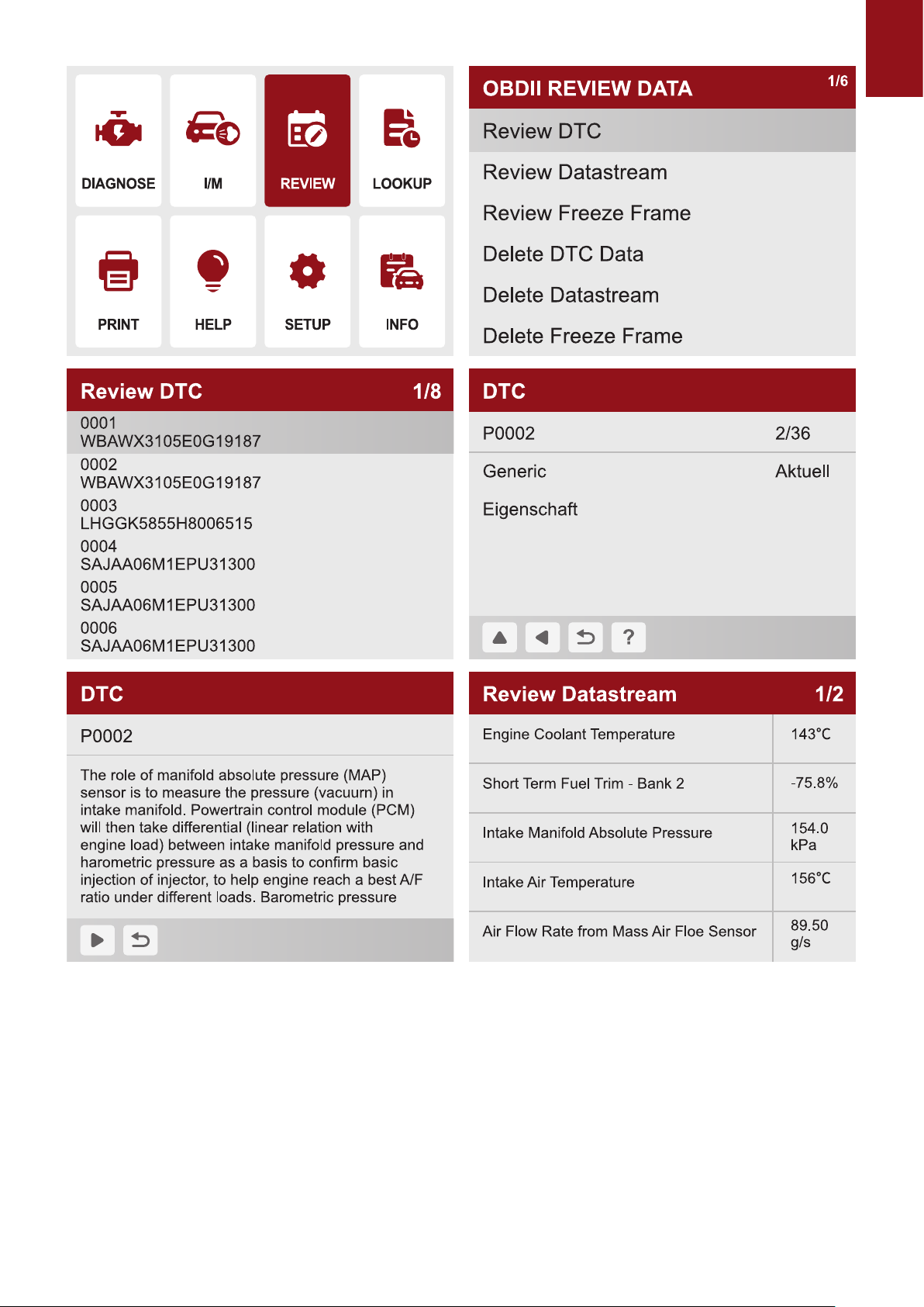
3. Select "REVIEW" and click "OK" to enter the REVIEW DATA list. Select "Review DTC" and
Next "OK" to View diagnostic records and delete records.
EN
4. Select "DTC LOOKUP" and click "OK" to query fault code analysis
EN
3. Diagnostic Trouble Codes (DTCs)
OBD II Diagnostic Trouble Codes are codes that are stored by the on-board computer diagnostic
system in response to a problem found in the vehicle. These codes identify a particular problem
area and is intended to provide you with a guide as to where a fault might be occurring within
a vehicle. OBDII Diagnostic Trouble Codes consist of a vedigit alphanumeric code. The rst
character, a letter, identi es which control system sets the code. The second character, a
number, 0-3; other three characters, a hex character, 0-9 or A-F provide additional information
on where the DTC originated and the operating conditions that caused it to set. Here below is an
example to illustrate the structure of the digits:
DTC Example
P0201
Systems
P=Powertrai
B=Body
C=Chassis
U=Network
ldentifies what section of the
system is malfunctioning
Code Type
0- Generic(SAE)
1 - Manufacturer Specic
2- Generic ('P”Codes) and
Manufacturer
Specic ("B”,“C”and
“U”Codes)
3- Includes both Generic
and Manufacturer
Specic Codes
Sub-systems
Identifies the system where the
problem is located.“P”Code systems
are listed below.“B”,“C”and“U”Code
system will vary.
0 - Fuel and air metering; Auxiliary
emlssion controls
1 - Fuel and air metering
2 - Fuel and air metering (injector
circuit malfunction only)
3 - Ignition system or misre
4 - Auxiliary emission control system
5 - Vehicle speed control and idl
control system
6 - Computer output circuits
7 - Transmission
8 - Transmission
9 - Transmission
A - Hybrid Propulsion
B - Hybrid Propulsion
C - Hybrid Propulsion
EN
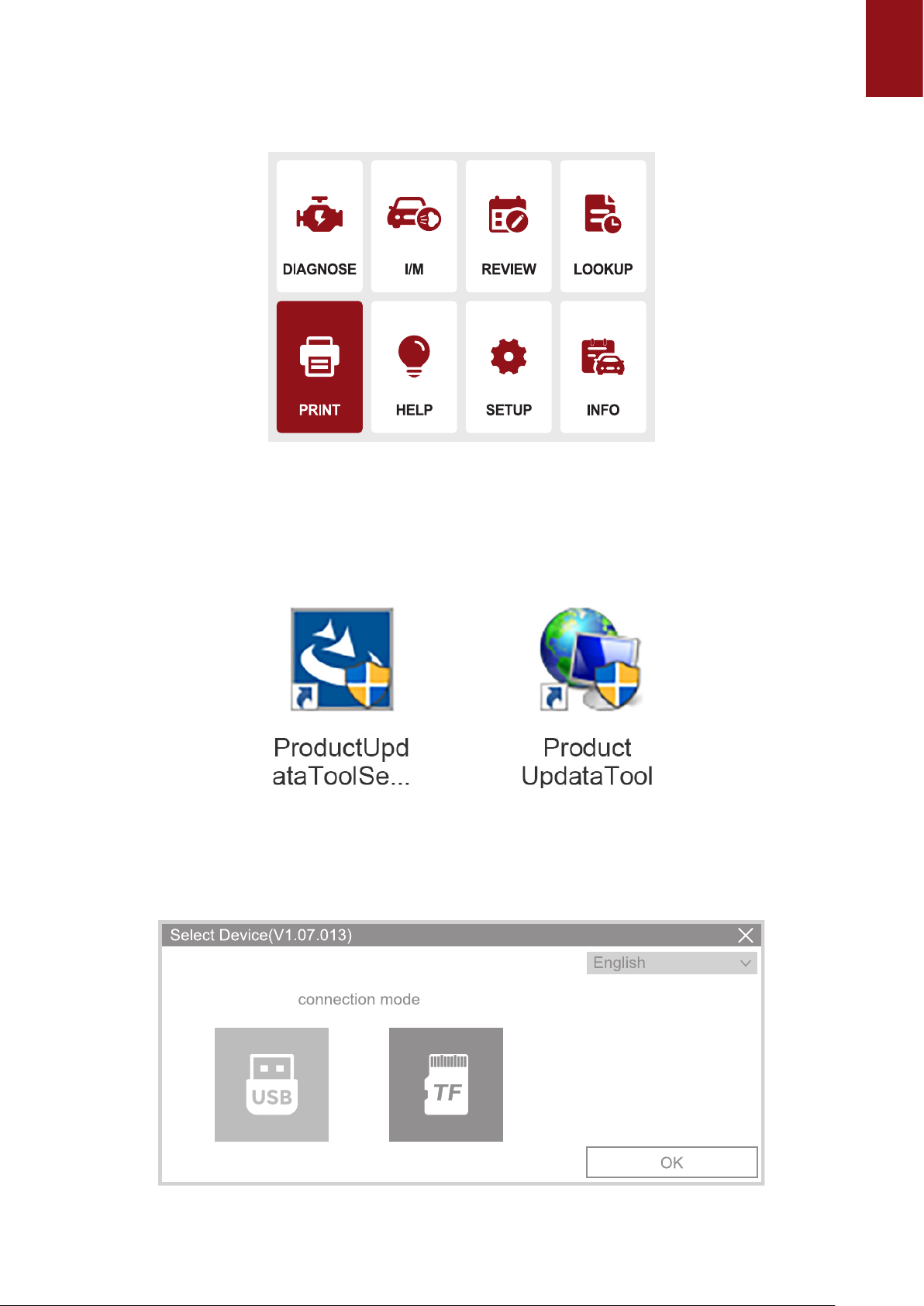
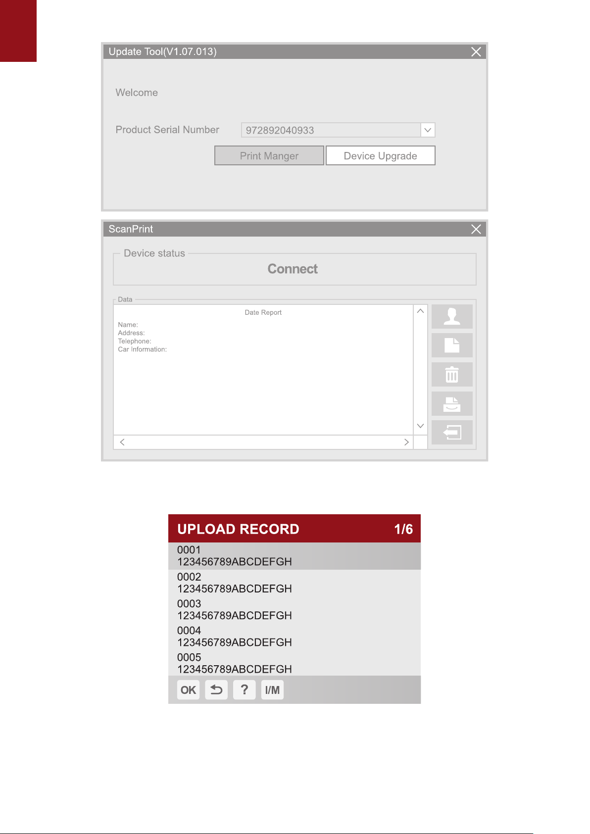
5. Select "Print" and click "OK" to enter the "UPLOAD RECORD" interface to view the
prompts, click "Help and I/M" to view the prompts and operate whether to delete the
information.
The rst step is to open the browser and enter the URL: https://mythinkcar.com/ to enter the
ocial website, click Download. A drop-down box will appear and select THINKOBD Update tool
of THINKOBD, and download the installation tool.
5.1When THINKOBD Update tool downloads the installation package successfully, the following
program will appear (as shown in the gure below):
5.2 The second step is to connect the computer and the OBD500 device via the MINI USB
identication port, open the Product Update Tool program, select the USB mode, and click the
OK button. After the automatic connection is successful, select Print Manager to enter the print
page;
EN
5.3 Click the OK button on the OBD500 device to enter the APP homepage, click PRINT
to select the report you want to print, and select the print button to complete.

EN
6. Select "Help" and click "OK". You will nd the device OBD function and system
instructions.
EN
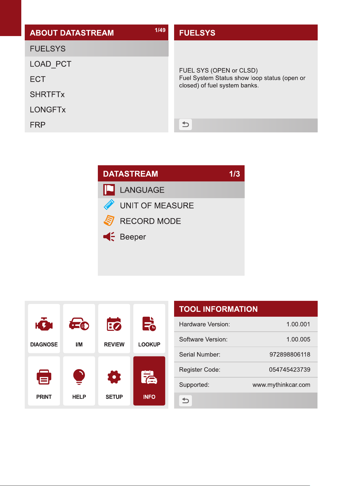
7. Select "Settings" and click "OK" to set the native language, unit of measure, record mode and
sound.
8.Select "info" and click "OK" to view local information
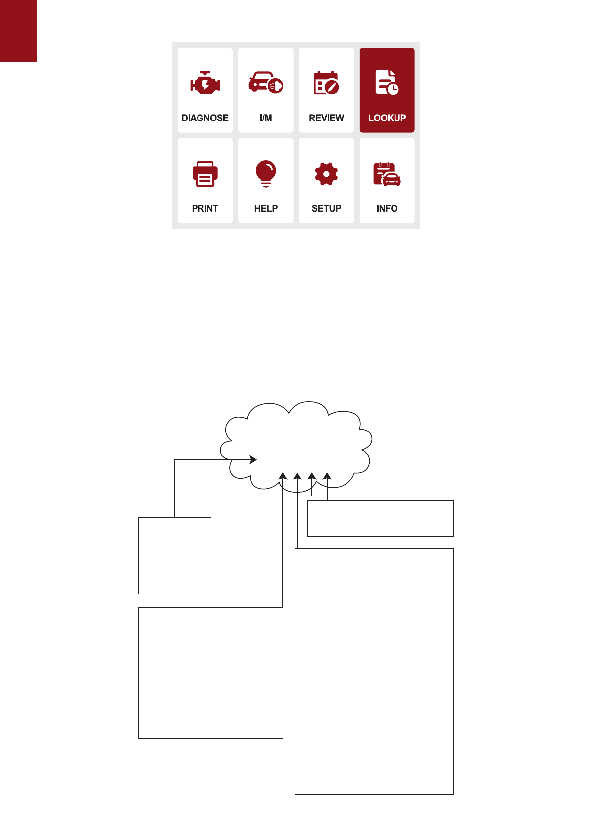
9. Update
The tool can be updated via a USB cable.
Note: Make sure that your computer has Internet connection.
1.1 Please log in to http://www.mythinkcar.com ocial website and nd the "THINKOBD

EN
Updata TOOL", download tool "Product Updata Tool Setup.exe" on your computer. Unzip
and install it on your computer (compatible with Windows XP, 7, 8, and 10).
When the installation is complete, connect one end of the USB data cable to the USB port of the
computer, Type-c port on the other end of the tool.
1.3 First insert the device into the computer identication port, then open the OBD500 upgrade
tool. Find the "COMFLG.INI" le and open, and change the "Serial Name" in the le as
same as the computer and device port "USB-COM name"
1.4 Finally, open the "CReaderV Plus Upgrade Tool.exe" of the OBD500 installation package
le, and click "Start Upgrade" to complete the upgrade.
Warranty Terms
This warranty applies only to users and distributors who purchase THINKCAR INC www.
thinkcar.com THINKCAR OBD500 products through normal procedures. Provide free warranty
within one year. THINKCAR warranty including electronic products for damages caused by
defects in materials or workmanship. Damages to the equipment or components caused by
abusing, unauthorized modication, using for non-designed purposes, operation in a manner
not specied in the instructions, etc.are not covered by this warranty. The compensation for
dashboard damage caused by the defect of this equipment is limited to repair or replacement.
THINKCAR does not bear any indirect and incidental losses. THINKCAR will judge the nature of
the equipment damage according to its prescribed inspection methods. No agents, employees
or business representatives of THINKCAR are authorized to make any conrmation, notice or
promise related to THINKCAR products.
Service Line: 1-833-692-2766
Ocial Website: www.thinkcar.com
Products tutorial, videos, FAQ and coverage list are available on THINKCAR ocial website.
Table of contents
Other Thinkcar Diagnostic Equipment manuals

Thinkcar
Thinkcar TK-IMT602 User manual

Thinkcar
Thinkcar THINKOBD 100 User manual

Thinkcar
Thinkcar TKTT3 Instruction manual

Thinkcar
Thinkcar THINKSCAN Max User manual

Thinkcar
Thinkcar X10 User manual

Thinkcar
Thinkcar ADAS User manual

Thinkcar
Thinkcar ThinkTool PD8 User manual

Thinkcar
Thinkcar THINKTPMS G1 User manual


