AU Tool CT-200 User manual
AUTOOL CT200
www.autooltech.com
Injector Cleaner & Tester
User Manual

Copyright Information
All rights reserved by AUTOOL TECH. CO., LTD. No part of this publication may be
reproduced, stored in a retrieval system, or transmitted in any form or by any means,
electronic, mechanical, photocopying, recording or otherwise, without the prior
written permission of AUTOOL. The information contained herein is designed only
for the use of this unit. AUTOOL is not responsible for any use of this information as
applied to other units.
Neither AUTOOL nor its affiliates shall be liable to the purchaser of this unit or third
parties for damages, losses, costs, or expenses incurred by purchaser or third
parties as a result of: accident, misuse, or abuse of this unit, or unauthorized
modifications, repairs, or alterations to this unit, or failure to strictly comply with
AUTOOL operating and maintenance instructions.
AUTOOL shall not be liable for any damages or problems arising from the use of any
options or any consumable products other than those designated as Original
AUTOOL Products or AUTOOL Approved Products by AUTOOL.
Other product names used herein are for identification purposes only and may be
trademarks of their respective owners. AUTOOL disclaims any and all rights in those
marks.
This unit is made for the purpose of persons who have special techniques and
certifications.
Manual are either trademarks, registered trademarks, service marks, domain names,
logos, company names of or are otherwise the property of AUTOOL or its affiliates. In
countries where any of the AUTOOL trademarks, service marks, domain names,
logos and company names are not registered, AUTOOL claims other rights
associated with unregistered trademarks, service marks, domain names, logos, and
company names. Other products or company names referred to in this manual may
be trademarks of their respective owners. You may not use any trademark, service
mark, domain name, logo, or company name of AUTOOL or any third party without
permission from the owner of the applicable trademark, service mark, domain name,
logo, or company name. You may contact AUTOOL by visiting AUTOOL at
https://www.autooltech.com, or writing to aftersale@autooltech.com, to request
written permission to use Materials on this manual for purposes or for all
other questions relating to this manual.

1 Overview
1.1 Functions and features
Fuel injector diagnostic and cleaning equipment is a mechatronics product that
combines ultrasonic cleaning technology and microcomputer oil pressure closed-
loop control cleaning and detection technology. This product simulates various
operating conditions of the engine, and cleans and inspects the fuel injectors of
various automobiles and motorcycles. This equipment is the necessary and
preferred equipment for the automobile and motorcycle repair and maintenance
industry, research and teaching and training departments.
Main functions
● Ultrasonic cleaning can be performed on single or
multiple injectors at the same time, which can remove the attachments and internal
blockages on the injectors.
● Uniformity detection: to detect the uniformity of the injection volume of each
injector.
● Atomization observation: Using the background light, you can observe the
spray atomization situation of the nozzle in a comprehensive and careful manner.
● Tightness test: It can detect the tightness and dripping of the fuel injector
under high pressure.
● Fuel injection volume detection: It can detect the fuel injection volume of the
fuel injection nozzle under specific working conditions (such as the same time
and the same number of times).
Main features
● Using ultrasonic powerful cleaning technology, strong cleaning ability.
● Using electronic pressure regulating control technology, stable oil pressure and
wide adjustable range.
● Use high-quality oil pump to ensure long-term stable use.
● The use of high-definition digital tube display makes the operation clear and
easy to learn.
● The oil tank liquid level is displayed visually, and the detection liquid can be
recycled.
● Bright background light, you can clearly see the various situations of the fuel
injector when it is working
● It has replaceable composite joints suitable for a variety of vehicle types.
● Within the allowable adjustment range, the test time, working frequency, fuel
injection times, shortest switching period, etc. of the fuel injector can be adjusted
arbitrarily.
Ultrasonic cleaning:

1.2 Working environment and technical parameters
Working environment
Power supply: AC220V±10%
Frequency: 50HZ±0.5
Relative humidity: <85%
Environment temperature: 0℃~+40℃
External magnetic field strength: <400A/m
No open flames are allowed around
Technical parameters
Tank capacity:1300 ml
Range of rotation:0-7500r/min
PWM pulse width:0~20.0ms step0.1ms
Time:0~20min
Cleaning frequency:40 kHz
Cylinder volume:180 ml
Injection times:0~9900 times, step 100ms
System pressure:0~0.6Mpa
Ultrasonic cleaning power:70W
Package dimensions:340*295*360mm

2 Structure and composition
2.1 Structure
1-Lock pole;2-Lock nut;3-Oil rail;4-Top oil inlet connector;5-Glass measuring
cylinder;6-Oil drain handle;7-Ultrasonic cleaning tank;8-Operation panel;
9-Pressure gauge;10-Cleaning agent drain valve;11-Oil outlet pipe;
12-Power switch;13-Power socket;14-Signal wire;15-Oil fill-in port;
16-Testing agent liquid level
2.2 Operation panel diagram
Pulse width/function window: display the selected function item when
the function is selected, and display the pulse width of the injector when
working.
Time window: display the working time of the fuel injector and the number
of fuel injection.
Pulse width adjustment button: Adjust the pulse width of the injector
when working
● Press up to increase the working pulse width of the injector when
cleaning the injector.
● Press down to clean the injector to reduce the working pulse width of
the injector.
⑯
①
②
③
④
⑤
⑥
⑦
⑧
⑨
⑩
⑪
⑫
⑬
⑭
⑮

Time/time adjustment button: adjust the working time of the injector and
the number of injections.
● Press up to increase the working time of the injector/the number of
injections.
● Press down to reduce the working time of the injector/the number of
injections.
Start button: Press to execute the selected work item.
Pause button: temporarily stop the selected work item after pressing.
Stop button: stop the selected work item and return to the selected work
item.
Function selection button: select work item.
● Press up to select work item.
● Press the down to select the work item.
Pressure adjusting knob: adjust pressure change.
● Turn clockwise to increase the pressure value.
● Turn counterclockwise to decrease the pressure
3 Operation process
3.1 Ultrasonic cleaning
Ultrasonic cleaning is to use the penetrating and cavitation shock waves generated
when ultrasonic waves propagate in the medium, and powerfully clean objects with
complex shapes, cavities and pores to completely remove stubborn carbon
deposits on the fuel injector.
3.1.1 Preparation
1) Remove the fuel injector from the vehicle and check whether its rubber seal is
damaged. If it is damaged, it should be replaced in time before the cleaning test to
avoid leakage during the test. Then put the fuel injection nozzle into the cleaning
agent, carefully remove the external grease and wipe it with a soft cloth.
2) Turn on the power and turn on the power switch on the side of the main unit.
3) Put the cleaning bracket in the accessories into the ultrasonic cleaning tank, and
place the wiped fuel injector in the cleaning bracket positioning hole of the
ultrasonic tank.
3.1.2 Methods and steps
1) Add an appropriate amount of cleaning agent to the ultrasonic tank and
spread the cleaning agent over the bottom of the cleaning stand.

2) Insert the plugs of the drive wires into the injector sockets in turn. (Special fuel
injectors need to be connected with an adapter cable)
3) Press the item selection up and down keys to select the "01 ultrasonic cleaning"
item, and then press the working time up and down keys to set the time. (The
system defaults to 10 minutes, if you need to modify the time, you can use the up
and down keys to change)
4) Press the start button and turn on the ultrasonic cleaning switch on the side of
the device to start cleaning. When working, you can press the pause button to
suspend work or press the stop button to exit.
5) During the cleaning process, the heating switch on the side of the equipment can
be turned on to improve the cleaning effect.
The working time gradually decreases. When it is 0, the system automatically
stops.
Take out the fuel injection nozzle from the ultrasonic tank, wipe the cleaning liquid
on it with a soft cloth, and prepare for the next job.
NOTICE
● During the cleaning process, you can hear the intermittent (approximately 5
seconds) vibrating sound when you take the fuel injector out and put it to your ear,
so you can judge whether the fuel injector is working normally.
● Ultrasonic cleaning is strictly prohibited when there is no cleaning agent in the
ultrasonic tank to avoid equipment damage.
● Only the ultrasonic cleaning agent dedicated to cleaning the fuel injection
nozzle can be added to the ultrasonic tank, and other reagents cannot be used
instead, otherwise any malfunctions and damages caused will not be covered by
the warranty.
3.2 Injector diagnostic
This function is to detect the atomization, dripping, blockage, fuel injection angle
status of the fuel injectors and the size and balance of the fuel injection of each fuel
injector at different speeds.
3.2.1 Preparation
1) Confirm that the oil drain handle is open, use the funnel in the
accessories to
add the test liquid to the equipment through the glass window, and pay
attention to control the flow rate during the addition to avoid overflow.
2) Add 1 bottle (about 1000ml) of testing agent each time.
3) Install the fuel injector.
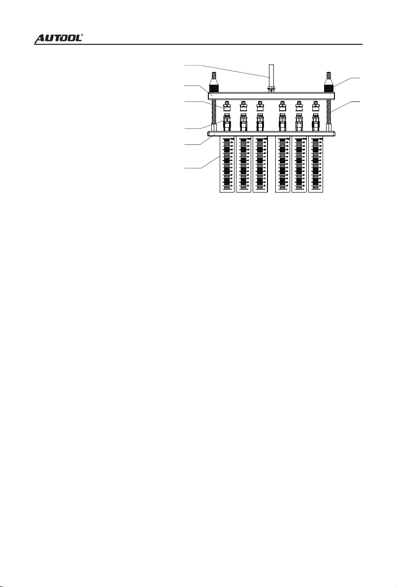
Top-in fuel injector installation diagram
● Select the top oil inlet connector from the accessories and install it into the oil
separator.
● Install the fuel injector in the forward direction (apply a little grease on the "O"
ring of the fuel injector)
● Put the horizontal end of the oil separator and the fuel injector on the upper
plate seat, and tighten the two ends with the locking rod. Ready to test.
3.2.2 Methods and steps
02 Idle speed test
1) Confirm that the injector to be tested has been installed properly and the signal
wire has been plugged in.
2) Select "02 Idle Speed Test".
3) Press the working time up and down keys to set the time. (Generally set to 2
minutes)
4) Press the start button to start work.
5) Turn the pressure adjustment knob to adjust the pressure to 0.25~ 0.3 MPa. (In
the electronic injection system, the general oil pressure works at 0.25-0.3MPa)
6) Press the up and down keys to select the appropriate pulse width. (The system
default is 3ms).
7) The working time gradually decreases. When it is 0, the system automatically
stops.
03 Medium speed test
1) Select "03 Medium Speed Test".
2) Press the start button.
1-Oil outlet pipe;
2-Oil rail;
3-Top oil inlet connector;
4-Injectors;
5-Upper plate seat;
6-Glass measuring cylinder;
7-Lock nut;
8-Lock pole
①
②
③
④
⑤
⑥
⑦
⑧

3) The rest of the operation steps are consistent with item 02
04 High speed test
1) Select "04 High Speed Test".
2) Press the start button.
3) The rest of the operation steps are consistent with item 02
05 Accelerating test
1) Select “05 Accelerating Test”.
2) Press the start button.
NOTICE
● The fuel pressure, working time and pulse width are automatically set by the
system. The time system defaults to 10s as a cycle period, and the user does not
need to set it separately.
● The system will automatically and continuously cycle three times to simulate
the working condition and fuel injection volume of the fuel injector when the engine
is accelerating uniformly at 750 to 7500 rpm.
06 Variable speed test
1) Select “06 Variable Speed Test”.
2) Press the start button.
NOTICE
● The fuel pressure, working time and pulse width are automatically set by the
system. The time system defaults to a cycle of 10s, and the user does not need to
set it separately.
● The system will automatically and continuously cycle three times to simulate
the working condition and fuel injection volume of the fuel injector when the engine
is idling (750 rpm), medium speed (4500 rpm), and high speed (7500 rpm).
07 Leakage test
1) Select "07 Leak Test".
2) Press the working time up and down buttons to set the time. (Generally set to 1
minute)
3) The rest of the operation steps are consistent with item 02.
NOTICE
● The pulse width system defaults to 3ms, no need to set it again.
● Whether the fuel injection nozzle is dripping and leaking when the simulated oil
pressure is 0.3Mpa
08 Idle speed spray volume test
1) Select "08 Idle Spray Volume".

2) Press the up and down buttons to set the number of times. (Generally set to
2000 times)
3) Press down on the oil drain handle to observe the fuel injection volume.
4) Press the start button to start the test.
5) After the test, raise the drain handle and put the testing agent back into the tank.
Description: Simulate the working conditions and fuel injection volume of the engine
when the fuel injection nozzle works for a certain number of times when the engine
is idling.
09 Medium speed spray volume test
1) Select “09 Medium Spray Volume”.
2) The rest of the operation steps are consistent with item 08.
10 High speed spray volume test
1) Select “10 High Spray Volume”.
2) The rest of the operation steps are consistent with item 08.
NOTICE
● Flow balance Test the flow balance at different speeds. When the liquid level in
the measuring cylinder is 2/3 of the measuring cylinder, pause or stop work to
observe the balance of the fuel injection volume. The deviation of the fuel injection
volume of all fuel injection nozzles on a vehicle should not exceed 2%. Or refer to
the relevant technical manual of the fuel injector to judge the flow balance of the
fuel injector.
● Observation of fuel injection shape Observe whether the fuel injection shapes
and angles of all fuel injection nozzles on the same car are uniform at various
speeds. At the same time, you can adjust the opening pulse width of the fuel
injection nozzle to check whether the minimum opening pulse width of the fuel
injection nozzle is consistent.
● Leak detection test Leak detection test is to detect the tightness of the injector
needle valve under the high pressure of the system. (Observe the tightness of the
fuel injector, generally there should be no leakage within one minute)
11 Unit info
Display the product number and date of manufacture of the device.
4 Storage and maintenance
4.1 Storage
1) Turn off the power and unplug the power plug.
2) Put all connectors back into the accessory box for storage.

3) Drain the ultrasonic cleaning agent. Wipe the equipment clean with a dry soft
cloth.
4) If the machine needs to be stored for a long time, discharge the testing agent
into a bottle and seal it.
4.2 Maintenance
● Replacement of testing agent After the testing agent has been used for a
period of time, a lot of impurities will accumulate, and the agent containing dirt
cannot be used, otherwise it will easily block the fuel injector. When replacing the
agent, first open the testing agent drain valve to empty the tank, and then inject a
little testing agent to clean the interior of the tank. After cleaning, drain the fuel tank
again and then pour 1L of new testing agent into the tank.
● Fuse replacement there is a square box marked with a fuse on the power
socket on the left side of the device, and the fuse can be seen by opening the box.
If it is blown, replace it with a new one.
5 Precautions
Since the test device is part of quartz glass, it is easy to break, so do not place
other objects around the equipment to avoid bumping and breaking.
● If there is no digital display after power on, please check whether the power
supply is powered; if so, check whether the plug is connected firmly, or whether the
fuse is blown. If it is not broken, and the switch is still invalid after pressing the
switch several times intermittently, please contact the manufacturer and must not
disassemble it by yourself, otherwise our company will not provide warranty.
● When no cleaning agent is added to the ultrasonic tank, it is strictly prohibited
to open the ultrasonic cleaning item to avoid damage to the ultrasonic system.
● Every time the test solution is changed, it must be cleaned up, and then 1L of
new test solution should be added.
● The use of unqualified testing agent will cause corrosion of the oil pump, oil
supply pipeline and failure of the pressure gauge.
● Using other cleaning agent and testing agent will cause the equipment surface
coating to peel off.
● It is strictly forbidden to use kerosene, gasoline or other testing agent and
cleaning agents as testing agent and cleaning agents for this machine. Otherwise,
the "O" ring and pipeline rubber parts in the equipment will be damaged, causing
leakage.
● The cleaning agent and testing agent should not be mixed up.

6 Warranty
1. Thank you for choosing our products, we will provide you with the following
services and promises.
2. The warranty period of this product is 1 year.
3. After the warranty period expires, repairs will be charged for replacement parts.
4. After the failure, please contact the manufacturer, we will give you the most
complete service in the shortest time.
The following items are not covered by the warranty:
1) Vulnerable parts are not covered by the warranty, including: glass tube, signal
sire, stickers, connectors pressure gauge, oil outlet pipe.
2) When no cleaning agent is added to the ultrasonic tank, turning on the ultrasonic
cleaning switch will damage the ultrasonic system, which is not covered by the
warranty.
3) If the testing agent is not replaced in time after long-term use, the oil pump filter
screen is blocked and the oil pump is burned out of the warranty.
4) The use of fuel injector cleaning agent as fuel injector testing agent will cause the
fuel pump to burn out, which is not covered by the warranty.
5) Man-made faults are not covered by the warranty.
Disclaimer: All information, illustrations, and specifications contained in this manual,
AUTOOL resumes the right of modify this manual and the machine itself with no prior
notice. The physical appearance and color may differ from what is shown in the
manual, please refer to the actual product. Every effort has been made to make all
descriptions in the book accurate, but inevitably there are still inaccuracies, if in doubt,
please contact your dealer or AUTOOL after-service centre, we are not responsible
for any consequences arising from misunderstandings.


Other manuals for CT-200
1
Table of contents
Other AU Tool Diagnostic Equipment manuals


Popular Diagnostic Equipment manuals by other brands

Pro-tec
Pro-tec PROGNOST C Instructions for use

Pro-tec
Pro-tec PRS 500 E Instructions for use

U.S. General
U.S. General 47860 Assembly and operating instructions

YIC Technologies
YIC Technologies EMScannerR Getting Started and Setup Guide

Spin
Spin SLEEK TFT Manual for use and maintenance

Diagnostic Associates
Diagnostic Associates DA-ST512 user manual


