Pro-tec PRS 500 E User manual

PROTEC GmbH & Co. KG
In den Dorfwiesen 14, 71720 Oberstenfeld, Germany
Version: 6.0
Issued: 2022-01-1
Subject to alterations
PRS 500 E
Basic diagnostic X-ray syst m
Mod l/ID: 7069-9-8050_Vxxx
Basis UDI-DI: 426050264X005ZK
Instructions for us
Ident. Nr. 506 -0-8002

NOTE
All sheets of this document contain proprietary and confidential information of
PROTEC GmbH & Co. KG and is intended for exclusive use by current PROTEC GmbH
& Co. KG customers. Copying, disclosure to others or other use is prohibited without
the express written consent of PROTEC´s law department. Knowledge of violations
of these regulations must be reported immediately to PROTEC GmbH & Co. KG.
© 2022 PROTEC GmbH & Co. KG, Oberstenfeld
These accompanying documents were created and distributed by the documentation department.
Comments and questions about the documentation, please contact:
PROTEC GmbH & Co. KG
In den Dorfwiesen 14 | 71720 Oberstenfeld
Germany
Phone: (+ 4 ) 7062 – 2 55 0
Fax: (+ 4 ) 7062 – 2 55 60
E-Mail: protec@protec-med.com
Internet: www.protec-med.com

PRS 500 E
Instructions for use 506 -0-8002
PROTEC GmbH & Co. KG, In den Dorfwiesen 14, 71720 Oberstenfeld, Germany 3 von 47
Tabl of cont nts
Pag
Tabl of cont nts ........................................................................................................................... 3
R vision Status .............................................................................................................................. 6
G n ral Not s ................................................................................................................................ 7
M chanical – El ctric Warning .................................................................................................... 7
Radiation Warning ........................................................................................................................ 7
To th Us r ..................................................................................................................................... 8
1
D vic D scription .............................................................................................................. 9
1.1 Introduction .........................................................................................................................................................................................
1.2 Description............................................................................................................................................................................................
1.2.1 System Components .........................................................................................................................................................
1.2.2 Hardware and Network System Requirements .................................................................................................
1.2.3 Installation ............................................................................................................................................................................. 10
1.2.3.1 Floor capacity ................................................................................................................................................................ 10
1.3 Performance Characteristics ................................................................................................................................................... 10
1.3.1 Height-adjustable X-ray System Table ................................................................................................................. 10
1.3.2 X-ray tube support stand ............................................................................................................................................. 11
1.3.3 Image receptor floor stand.......................................................................................................................................... 11
1.4 Intended use ..................................................................................................................................................................................... 11
1.5 Clinical Benefit ................................................................................................................................................................................. 11
1.6 Patient Target Group(s) .............................................................................................................................................................. 11
1.7 Medical Conditions to be diagnosed ................................................................................................................................ 11
1.8 Indication and Contraindication .......................................................................................................................................... 12
1.8.1 Indications ............................................................................................................................................................................. 12
1.8.2 Contraindications .............................................................................................................................................................. 12
1. Intended User Group ................................................................................................................................................................... 12
1.10 Declaration of Conformity ........................................................................................................................................................ 12
2
Saf ty Instructions ............................................................................................................ 13
2.1 General Safety Instructions ...................................................................................................................................................... 15
2.1.1 Requirements for Operation ...................................................................................................................................... 15
2.1.2 Device Operation .............................................................................................................................................................. 15
2.1.2.1 Operating Type ............................................................................................................................................................ 15
2.1.3 Operating Personnel ....................................................................................................................................................... 15
2.1.4 Crushing and Collision Hazard .................................................................................................................................. 16
2.1.5 Explosion protection ....................................................................................................................................................... 16
2.1.6 Radiation Protection ........................................................................................................................................................ 16
2.1.7 Ventilation .............................................................................................................................................................................. 16
2.1.8 Interaction with Other Devices ................................................................................................................................. 16
2.1. Electromagnetic Environment and the influence of devices ................................................................ 17
3
Control El m nts and Displays ....................................................................................... 18
3.1 Main Switch of the X-ray system .......................................................................................................................................... 18
3.2 Emergency Stop Switches of the X-ray system ........................................................................................................... 1
3.2.1 X-ray System Table Emergency Stop Switch.................................................................................................... 1
3.2.2 Generator Emergency Stop Switch ........................................................................................................................ 1
3.3 Control Elements and Display of PROGNOST E........................................................................................................... 1
3.4 Control Elements and Display of PROGNOST SH ....................................................................................................... 1
3.4.1 PROGNOST SH ..................................................................................................................................................................... 1
3.4.2 PROGNOST SH TOUCH ................................................................................................................................................... 20
3.4.3 Foot pedal .............................................................................................................................................................................. 21
3.5 Control Elements and Display of collimator ................................................................................................................. 22
3.6 Control Elements and Display of X-ray tube ................................................................................................................. 23
3.7 Control Elements and Display of X-ray generator ..................................................................................................... 23
3.8 Control Elements of Bucky, Grid entity ............................................................................................................................. 23

PRS 500 E
Instructions for use 506 -0-8002
PROTEC GmbH & Co. KG, In den Dorfwiesen 14, 71720 Oberstenfeld, Germany 4 von 47
3. Control elements and device displays of vertical X-ray system image receptor stand PROVERT 24
3. .1 Vertical carriage .................................................................................................................................................................. 24
3.10 Control elements and device displays of RAPIXX system ..................................................................................... 24
3.11 Control elements and device displays of CONAXX 2 .............................................................................................. 24
4
Handling / Op ration ........................................................................................................ 25
4.1 Requirements before and during Operation ................................................................................................................ 25
4.2 Operation with the radiographic system ........................................................................................................................ 25
4.2.1 Operation at the X-ray system table ...................................................................................................................... 25
4.2.1.1 Position of patients on the tabletop ............................................................................................................... 25
4.2.1.2 Setting the X-ray unit on the mid moving Bucky, Grid entity ......................................................... 25
4.2.1.3 Inserting a cassette into the cassette tray .................................................................................................... 25
4.2.1.4 Adjusting the focus-film distance (FFD) ........................................................................................................ 25
4.2.1.5 Adjusting the light resp. X-ray field .................................................................................................................. 25
4.2.1.6 Exposure preparation / exposure release .................................................................................................... 26
4.2.1.7 Overtable exposures ................................................................................................................................................. 26
4.2.1.8 Exposures with the lateral detector holder (optional) ......................................................................... 26
4.2.2 Operation at vertical X-ray system image receptor stand PROVERT ................................................. 27
4.2.2.1 Adjustment of the X-ray unit to the mid of a cassette or Bucky/Grid entity of a X-ray
system image receptor stand (vertical center beam) ................................................................................................. 27
4.2.2.2 Adjustment of the source to image-receptor distance (SID) ........................................................... 27
4.2.2.3 Adjustment of the light-/ radiation field....................................................................................................... 27
4.2.2.4 Exposure preparation/ release ............................................................................................................................ 27
4.3 Operation of the X-ray system table PROGNOST E ................................................................................................... 27
4.4 Operation of the collimator ..................................................................................................................................................... 27
4.5 Operation of the X-ray tube .................................................................................................................................................... 28
4.6 Operation of the X-ray generator ........................................................................................................................................ 28
4.7 Operation of the Bucky, Grid entity .................................................................................................................................... 28
4.8 Operation of the vertical X-ray system image receptor stand PROVERT ..................................................... 28
4. Operation of the RAPIXX system .......................................................................................................................................... 28
4.10 Operation of the Software........................................................................................................................................................ 28
4.11 Function of the PRS 500 E......................................................................................................................................................... 28
4.11.1 Switching the PRS 500 E on and off ....................................................................................................................... 28
4.11.2 Dosimetric Calibration ................................................................................................................................................... 28
4.12 Automatic Exposure Control .................................................................................................................................................. 2
5
Saf ty and Maint nanc ................................................................................................... 30
5.1 Introduction ...................................................................................................................................................................................... 30
5.2 Reusability .......................................................................................................................................................................................... 30
5.3 Cleaning and disinfection ......................................................................................................................................................... 30
5.3.1 Cleaning .................................................................................................................................................................................. 30
5.3.2 Disinfection ........................................................................................................................................................................... 30
5.4 Inspection and maintenance ................................................................................................................................................. 31
5.4.1 Daily Monitoring before and during the Examination operation ....................................................... 31
5.4.2 Regular Monitoring .......................................................................................................................................................... 31
5.4.3 Maintenance ........................................................................................................................................................................ 31
5.4.4 Warranty .................................................................................................................................................................................. 31
5.4.5 Product Service Life ......................................................................................................................................................... 32
5.4.6 Further Information ......................................................................................................................................................... 32
5.4.7 Applied Parts and parts which get handled like an application part ................................................ 32
5.4.8 Disposal ................................................................................................................................................................................... 32
6
Pow r Supply ..................................................................................................................... 33
6.1 Electromagnetic Compatibility (EMC) after EN 60601-1-2 ................................................................................... 33
6.1.1 Guidelines and Manufacturer’s Declaration – Electromagnetic interference .............................. 34
7
T chnical Data .................................................................................................................... 37
7.1 Dimensions ........................................................................................................................................................................................ 37
7.2 X-ray system table PROGNOST E .......................................................................................................................................... 3
7.3 Bucky, Grid entity ........................................................................................................................................................................... 3
7.4 X-ray tube column ........................................................................................................................................................................ 40

PRS 500 E
Instructions for use 506 -0-8002
PROTEC GmbH & Co. KG, In den Dorfwiesen 14, 71720 Oberstenfeld, Germany 5 von 47
7.5 Vertical X-ray system image receptor stand .................................................................................................................. 40
7.6 Attenuation Equivalent .............................................................................................................................................................. 41
7.6.1 Protection Art and Protection Class ....................................................................................................................... 41
7.7 Automatic Cut-off Dose ............................................................................................................................................................. 41
7.7.1 Analogue System .............................................................................................................................................................. 41
7.7.2 Digital System ...................................................................................................................................................................... 41
7.8 Environmental Conditions ....................................................................................................................................................... 41
7.8.1 Environmental Conditions during Operation .................................................................................................. 41
7.8.2 Environmental Conditions for Shipping and Storage ................................................................................ 41
8
D scription of symbols, lab ls and abbr viations ....................................................... 42
8.1 Symbols ............................................................................................................................................................................................... 42
8.2 Identification label......................................................................................................................................................................... 44
8.3 Labels .................................................................................................................................................................................................... 44
8.4 Position symbols and labels .................................................................................................................................................... 46
8.5 Abbreviations ................................................................................................................................................................................... 47

PRS 500 E
Instructions for use 506 -0-8002
PROTEC GmbH & Co. KG, In den Dorfwiesen 14, 71720 Oberstenfeld, Germany 6 von 47
NOTE
The information contained in this document conforms to the configuration of the
equipment as of the date of manufacture. Revisions to the equipment subsequent
to the date of manufacture will be addressed in service updates distributed to the
PROTEC Technical Service Organisation.
R vision Status
R vision
Dat Updat d pag s Comm nts Author
1.0
201 -05-14
all
New created, replaces
document 508 -0-0002_V5
-
2.0
201 -08-27
Cap. 1.2, 6. 1.1, 7.1, 8.1,
8.2, 8.4
GMDN terms updated
Changed optional
accessories and images
dimension
EMC tables removed
Symbols added
Identification label updated
-
3.0 2020-06-1
Cap. 1.2.2.1, 1.3.2, 3.2, 7.4
Telescopic arm added
-
4.0 2020-08-11
Front page, Cap. 5.3.3 Maintenance updated
-
5.0 2020-11-12
Cap. 1.2.1; Cap.6; Cap.
3.1.1; Cap. 3.1.2; Cap.
4.1.1.8
New generators, Rotatable
X-ray column added
-
6.0
2022-01-1
Titelseite, Kap. 3.2.3; Kap.
1.2.2; Kap. 1.2.2.1; Kap.
1.3.2; Kap. 7.1
Basis UDI-DI new; Note
Rotation; Note Installation
new; total weight changed;
ceiling height changed;
Traverse paths PROGNOST
SH changed vertically;
translation cpl. revised
ML

PRS 500 E
Instructions for use 506 -0-8002
PROTEC GmbH & Co. KG, In den Dorfwiesen 14, 71720 Oberstenfeld, Germany 7 von 47
G n ral Not s
WARNING!
In ord r to maintain th s t and t st d r quir m nts of th 60601 s ri s of
standards, th ME syst m must not b modifi d during its actual op rating
lif .
M chanical – El ctric Warning
WARNING!
All of th movabl ass mbli s and parts of this quipm nt should b op rat d
with car and routin ly insp ct d in accordanc with th manufactur r's
r comm ndations contain d in th quipm nt Accompanying Docum nts.
Maint nanc and s rvic is only to b p rform d by Custom rs authoriz d by
PROTEC GmbH & Co. KG.
Liv l ctrical t rminals ar d adly.
Do not r mov fl xibl high-t nsion cabl s from X-ray tub cov r or high-
t nsion g n rator and/or acc ss cov rs from X-ray g n rator.
For all compon nts of th quipm nt prot ctiv arthing m ans must b
provid d in complianc with th national r gulations.
Failur to comply with th for going may r sult in s rious or fatal bodily
injuri s to th op rator or thos in th ar a.
Radiation Warning
WARING!
In th s accompanying docum nts, a syst m or a compon nt for such a
syst m is docum nt d, which is us d for th int nd d g n ration of X-rays in
m dical diagnostics.
X-rays ar ionizing radiation that can caus damag to living organisms ( .g.
canc r or mutations).
X-rays r pr s nt a pot ntial risk for pati nts and mploy s. Th r for , th
application of X-rays with a giv n m dical issu , must aim at th minimization
of radiation xposur for both groups of p opl .
Th group of p opl r sponsibl for th application must hav th n c ssary
sp cialist knowl dg in accordanc with th ordinanc s and guid lin s and
apply th proc dur s for th saf op ration of such syst ms.
Th national r gulations must also b obs rv d during planning and
installation.
Th X-rays ar cr at d in th X-ray tub by strong braking of pr viously
acc l rat d l ctrons, which mit n rgy in th form of l ctromagn tic
wav s. Th int nsity d p nds on th s t param t rs voltag (kV), curr nt
(mA) and tim (s) on th X-ray g n rator. Th X-rays ar only mitt d at a
radiation xit window of th tub and ar limit d by th collimator mount d
dir ctly b low.
Th X-ray compon nts from PROTEC us d ar only d vic s for th human
m dical diagnostic ar a, which can b s t up to a maximum of 150 kV. Furth r
information can b found in th t chnical data insid th instructions for us
for th g n rators, X-ray tub s and collimators.

PRS 500 E
Instructions for use 506 -0-8002
PROTEC GmbH & Co. KG, In den Dorfwiesen 14, 71720 Oberstenfeld, Germany 8 von 47
Th syst m caus s diff r nt ionising radiation. Th purpos is to cr at
charact ristic X-ray radiation. Th int nsity d p nds on th adjust d valu s of
voltag , curr nt and tim . Th radiation com s orthogonal out of th X-ray
tub and is limit d by th collimator.
To th Us r
NOTE
The user of these accompanying documents is required to carefully read through
and carefully consider the instructions, warnings and cautions contained therein
before starting operation.
Even if you have already operated similar systems, changes in the design,
production and functional routine of the system described here may have been
made, which have a significant influence on the operation.
Although the product was subject to a risk analysis and the design corresponds to
the current state of the art, residual risks remain in clinical use. These are displayed in
the following Instructions for use by application limits, contraindications, warnings
and precautions.
Assembly and service works on the system described here must be carried out by
authorised and qualified personnel from PROTEC GmbH & Co. KG. Assembly
personnel and other persons who are not employees of the technical service
department of PROTEC GmbH & Co. KG are requested to contact the local branch of
PROTEC GmbH & Co. KG before assembly or service work is started.
For assembly and service works, it is necessary to use the "Technical Description” of
the product and to observe the points it contains.
NOTE
The use of the product with add-on or accessory parts not authorized by PROTEC or
other unapproved components is not permitted.

PRS 500 E
Instructions for use 506 -0-8002
PROTEC GmbH & Co. KG, In den Dorfwiesen 14, 71720 Oberstenfeld, Germany von 47
1
D vic D scription
1.1 Introduction
The instructions for use describe the performance characteristics and operation required for efficient
and effective use of the PRS 500 E.
Before working with the PRS 500 E, the complete instructions for use must be read, especially the Safety
Instructions and the chapter Handling.
1.2 D scription
The PRS 500 E series radiography system is a complete and powerful easy-to-use bucky workplace
featuring high performance for the operator and a pleasant atmosphere for patients The complete
system delivers excellent image acquisition quality and is ideal for all types of X-ray examinations in
radiology centres, clinics and hospitals – regardless of whether analogue or digital imaging methods
are used.
1.2.1 Syst m Compon nts
The PROTEC X-ray system PRS 500 E consists of the following components:
•Stationary, height-adjustable X-ray table with floating tabletop,
•X-ray tube support stand with control arm,
•X-ray cassette holder (Bucky or Grid entity),
•Image receptor stand,
•X-ray generator,
•X-ray tube assembly with cover,
•Anti-scatter grid,
•Collimator.
Optional compon nts
•Measuring chamber (ionisation or solid state),
•Dose area product meter,
•Various DR systems (RAPIXX series, consisting of DR detector, Interface Box and CONAXX software).
Optional Acc ssori s
The following optional accessories are available for the PRS 500 E
X-ray system:
•Patient extending handle.
•Compression band.
•Mattress 225 cm x 70 cm x 2 cm.
•Short hand grip.
•Short hand grip adjustable.
•Long hand grip.
•Strain relief cable conduit image receptor stand.
•Lateral detector holder (only in connection with the rotatable X-ray column PROGNOST SH).
Acc ssori s which can influ nc th EMC-Condition
•Network cable (note the max. cable length in the component documentation).
•RAPIXX data connection cable (note the max. cable length in the component documentation).
•WLAN router or access points (only use devices approved by PROTEC).
1.2.2 Hardwar and N twork Syst m R quir m nts
If it is an X-ray system with optional system components for digital use, it should be ensured that the
country-specific requirements for data protection and IT security are met.
The system requirements for the optional system components (RAPIXX series) can be found in the
current document supplied, "EN_5330-0-0026_CONAXX2_System requirements".

PRS 500 E
Instructions for use 506 -0-8002
PROTEC GmbH & Co. KG, In den Dorfwiesen 14, 71720 Oberstenfeld, Germany 10 von 47
1.2.3 Installation
NOTE
The installation of the PRS 500 E must be performed by PROTEC service department
or a service company authorized by them.
This X-ray system PRS 500 E must be installed in a shielded X-ray room that complies with the national
regulations on radiation protection.
The room intended for the installation of the X-ray system must be prepared. This may need to include
changes to the routing of electrical connections to a central distribution cabinet. The electrical and
structural design of the room intended for the generator must comply with national regulations
(electrical and floor weight load).
For more information, please see separate “Installation manual” PRS 500 E.
Contact information of persons qualified to perform installations are available upon request at:
PROTEC GmbH & Co. KG
In den Dorfwiesen 14 | 71720 Oberstenfeld
Germany
Phone: (+ 4 ) 7062 – 2 55 0
Fax: (+ 4 ) 7062 – 2 55 60
E-Mail: protec@protec-med.com
Internet: www.protec-med.com
1.2.3.1 Floor capacity
NOTE
The X-ray system is primarily made of metal pieces. This has a corresponding effect
in the weight of the device.
The X-ray system PRS 500 E has a w ight of 894 kg (incl. generator).
Every technician is obliged to check the corresponding floor load before each
installation. Raised floors and hollow floors must also be considered.
1.3 P rformanc Charact ristics
1.3.1 H ight-adjustabl X-ray Syst m Tabl
•Variable table height
•PROGNOST E (58. cm – 87.6 cm).
•Floating tabletop.
•Tabletop colour: white.
•Motor-operated tabletop brake for effortless patient positioning.
•Low optimised distance between the tabletop surface and the image receptor surface.
•Large adjustment range of the tabletop for positioning the patient.
•High reliability.
•Side profile rails on the long sides of the tabletop for attaching accessories.
•Prepared for the installation of an X-ray cassette holder (Bucky or Grid entity) with anti-scatter
grid and a measuring chamber for operation with an automatic exposure control.
•Variable cassette / detector sizes can be used. Formats from 13 cm x 18 cm (5" x 7") to 43 cm x
43 cm (17" x 17"), depending on analogue or digital use.
•Suitable for a Bucky or a Grid entity (analogue or digital).

PRS 500 E
Instructions for use 506 -0-8002
PROTEC GmbH & Co. KG, In den Dorfwiesen 14, 71720 Oberstenfeld, Germany 11 von 47
1.3.2 X-ray tub support stand
•Ceiling-free column stand intended for use within rooms with a ceiling height of at least 2.35 m
/ standard and 2.40 m / with rotation X-ray column.
•Wide range of application
•Small wall distance allows good use of space.
•Control elements on the command arm are handily placed.
•Reproducible position of the X-ray assembly when rotating around the support arm axis
through angle indicator.
•Vertical travel range, focus height from 2 .7 cm to 18 .6 cm with horizontal beam path
•Electromagnetic brakes for the longitudinal movement of the column stand, the vertical
movement of the support arm, for the rotation of the X-ray tube assembly around the support
arm axis +/-180° with additional 0 ° detents as well as for the transversal movement of the
support arm +230 mm (optional).
•Safety coupling for the automatic centring of the X-ray tube assembly with the X-ray cassette
holder (Bucky or Grid entity).
1.3.3 Imag r c ptor floor stand
•Space-saving with a small footprint
•Wall and floor mounting or just floor mounting
•Left or right cassette loading
•Variable cassette / detector sizes can be used. Formats from 13 cm x 18 cm (5" x 7") to 43 cm x
43 cm (17" x 17"), depending on analogue or digital use.
•Suitable for a Bucky or a Grid entity (analogue or digital).
1.4 Int nd d us
The basic diagnostic X-ray systems of the PRS 500 series are intended for various routine applications in
planar X-ray imaging in human medicine.
They are stationary systems that can be used both for analogue and digital imaging.
1.5 Clinical B n fit
The clinical benefit of using diagnostic X-ray systems in human medicine is the generation of
conventional two-dimensional X-ray images for creation or specification of findings as a basis for
treatment decisions.
1.6 Pati nt Targ t Group(s)
The intended patient group includes all people for whom a justifying indication for a medical X-ray has
been given by a physician with the necessary expertise in radiation protection.
There are no general or fundamental restrictions on the patient group regarding age, gender, origin
and patient condition.
1.7 M dical Conditions to b diagnos d
A complete list of medical conditions that can be diagnosed is impossible for conventional
radiography, because the spectrum of conventional X-rays is very diverse and can vary in the course of
medical-technical progress.
Examples for medical conditions to be diagnosed:
•For the diagnosis of a bone fracture or bony injuries of the skeletal system or pathological
changes of hard tissues.
•For monitoring of correct reduction of bone fractures
•For the diagnosis of joint dislocations and ligament ruptures of the musculoskeletal system.
•For the diagnosis of degenerative, inflammatory, traumatic and tumorous diseases and
changes of the musculoskeletal system.
•For diagnostic of malformations and malalignments of the skeletal system.
•For the diagnosis of thoracic and pulmonary symptoms (thorax exposures)
•For the diagnosis of sclerotherapy.

PRS 500 E
Instructions for use 506 -0-8002
PROTEC GmbH & Co. KG, In den Dorfwiesen 14, 71720 Oberstenfeld, Germany 12 von 47
•For the diagnosis of inflammatory and expansive processes of the mucosa, cranial bones and
paranasal extension.
•For the diagnosis of the abdomen (e.g. acute abdomen, plain abdominal radiography,
urethrogram, cystogram).
1.8 Indication and Contraindication
1.8.1 Indications
According to §83 of the German radiation protection law (StrlSchG), an X-ray examination is only
justified if the patients benefit from X-ray diagnostics outweighs the radiation risk. The examination
method, means the conventional X-ray with the PRS 500 System, must be suitable to answer the
diagnostic question and no other more suitable alternative method is available.
Accordingly, it is also described by the International Atomic Energy Agency (IAEA) in the document
Radiation Protection and Safety of Radiation Sources: International Basic Safety Standards (Requirement
37: Justification of medical exposures). It also refers to the need to consider national or international
guidelines for the justification of a medical exposure.
NOTE
Even if, according to the justifying indication, the benefit predominates the radiation
risk, it must not be disregarded that there are residual risks due to ionising radiation
and that undesirable side effects may occur. Ionising radiation (X-radiation) can
damage the genome and, in the long term, lead to cancer and mutations and thus
damage the human body.
1.8.2 Contraindications
There are no absolute contraindications for conventional X-rays. But it is not allowed to make any
exposures on humans when they are not medically indicated (see justification of medical exposures,).
For pregnant women and children it is important to consider if the exposure is really necessary. It
should be avoided if possible.
1.9 Int nd d Us r Group
The X-ray systems of the PRS 500 series are intended exclusively for use by professional users who are
trained in the operation of diagnostic X-ray systems in accordance with the respective national
regulations and who are familiar with the proper handling, use and operation and also have been
instructed in the permitted conjunction with other medical products, objects and accessories.
Appropriate users can be, for example: X-ray technicians, X-ray assistants, medical technical X-ray
assistants, surgeons, casualty surgeons, orthopaedists and other trained medical personnel.
1.10 D claration of Conformity
This product is in conformity with the requirements of the European Community
Medical Device Directive 3/42/EEC from 06/14/1 3 including all current
revision standards.
The declaration of conformity is available directly from PROTEC:
PROTEC GmbH & Co. KG
In den Dorfwiesen 14 | 71720 Oberstenfeld
Telephone: +4 (0) 7062 – 2 55 0
Fax: +4 (0) 7062 – 2 55 60
E-Mail: protec@protec-med.com
Internet: www.protec-med.com

PRS 500 E
Instructions for use 506 -0-8002
PROTEC GmbH & Co. KG, In den Dorfwiesen 14, 71720 Oberstenfeld, Germany 13 von 47
2
Saf ty Instructions
NOTE
Contains information that must be observed during operation.
xxx
CAUTION!
Contains information which, if not observed, can cause property
damage.
xxx
WARNING!
Contains information which, if not followed, can cause personal
injury.
xxx
WARNING!
Warning of radioactive substances or ionizing radiation. Contains
information which, if not observed, can cause personal injury.
xxx
Settings and calibrations that are not described in these instructions for use must be carried out using
the technical description of the device by PROTEC service department or a service company authorized
by them.
NOTE
All instructions supplied with the PRS 500 E must be observed and the safety
instructions contained therein must be carefully read and adhered to.
NOTE
After the initial installation, the commissioning must be recorded with the PROTEC
acceptance protocol FB-04-07A4.
NOTE
In the case of a digital system, the instructions for CONAXX and RAPIXX must be
observed and the safety instructions contained therein must be carefully read and
adhered to.
NOTE
The X-ray system may only be commissioned if all safety measures for operator
protection have been met and checked. These protective measures can include
door contact, designated area, dosimeter, protective clothing, etc.

PRS 500 E
Instructions for use 506 -0-8002
PROTEC GmbH & Co. KG, In den Dorfwiesen 14, 71720 Oberstenfeld, Germany 14 von 47
CAUTION!
Th instructions for us contain all th information r l vant to saf ty in ord r
to g n rally put th X-ray syst m into op ration. Th d vic may only b
op rat d by appropriat ly train d and train d p rsonn l. In this cont xt,
op ration is nsur d by cl ar symbols on th control l m nts. All furth r
information and instructions can b found on th suppli d data carri r (USB,
CD or DVD). This information appli s in its ntir ty as an app ndix to th s
instructions for us and must b obs rv d.
NOTE
All control elements are marked with clear symbols on the control console and on
the swivel arm or the image receptor stand, which are described again in detail in
the corresponding instructions for use. The legal requirements regarding the
building regulations for an X-ray area must be met. The X-ray system must be tested
in accordance with the regulations in force in the country of installation and
approved by the appropriate body.
CAUTION!
If th wrong SID is s t for an xposur , it can hav a damaging ff ct on th
pati nt. Th inv rs squar law appli s. Halving th distanc l ads to a
radiation dos that is four tim s high r.
WARNING!
X-rays may not b p rform d on p rsons without a m dical justifying
indication. In th cas of pr gnant wom n and childr n, it must b car fully
consid r d wh th r an xposur is n c ssary. It should b avoid d if possibl .

PRS 500 E
Instructions for use 506 -0-8002
PROTEC GmbH & Co. KG, In den Dorfwiesen 14, 71720 Oberstenfeld, Germany 15 von 47
2.1 G n ral Saf ty Instructions
2.1.1 R quir m nts for Op ration
WARNING!
Th PRS 500 E is a prot ction class I d vic (according to EN 60601-1).
To avoid th risk of an l ctric shock, this d vic may only b conn ct d to a
supply n twork with a prot ctiv arthing conductor.
Th pow r supply for th PRS 500 E of th X-ray syst m is xclusiv ly mad by
dir ct conn ction to th X-ray g n rator or th Pow r Box and is p rman ntly
conn ct d th r . Th X-ray g n rator or th Pow r Box must hav at l ast 2
conn ctions for 230V 50/60Hz.
Th X-ray g n rator of th X-ray syst m is conn ct d to th supply n twork
(s t chnical d scription of th X-ray g n rator).
To r duc th risk of l ctric shock, th syst m must b conn ct d to a supply
n twork with prot ctiv arthing.
Th syst m do s not hav an on/off switch. It is switch d on or off dir ctly by
switching on th X-ray g n rator or by th switch on th Pow r Box. In ord r
to s parat any l ctrical voltag from th X-ray syst m, th conn ct d X-ray
g n rator or th Pow r Box must b switch d off.
2.1.2 D vic Op ration
In case of a malfunction, do not use the PRS 500 E anymore and notify PROTEC service department or a
service company authorized by them.
2.1.2.1 Op rating Typ
The PRS 500 E is not intended for continuous operation.
The separate maximum operating times must be taken from the individual components.
Duty Cycle: S3 15% - maximum continuous operation of 1,5 minutes.
2.1.3 Op rating P rsonn l
NOTE
Only trained and authorized personnel are allowed to work on the PRS 500 E.
NOTE
The operating personnel must be familiar with all warning signs attached to the PRS
500 E. They are used for your own safety and that of others and ensure proper
operation.

PRS 500 E
Instructions for use 506 -0-8002
PROTEC GmbH & Co. KG, In den Dorfwiesen 14, 71720 Oberstenfeld, Germany 16 von 47
2.1.4 Crushing and Collision Hazard
WARNING!
It must b nsur d that wh n op rating th moving parts of PRS 500 E, no
p rsons or obj cts ar in th obvious dang r ar a of th d vic . If not
obs rv d, it can r sult in p rsonal injury or damag to th PRS 500 E or oth r
obj cts.
2.1.5 Explosion prot ction
The PRS 500 E is not designated for use within areas with explosive hazards.
2.1.6 Radiation Prot ction
X-rays can pose a risk to patients and other people if the regulations for the operation of such systems
are not observed.
For this reason, the principles of radiation protection must have top priority and must be strictly
adhered to:
•K ping distanc from th radiation sourc
The dosage is reduced as a factor of the square of the distance from a (dot shaped) radiation source.
Double the distance ¼ dose, triple the distance 1/ dose, etc.
The dose decreases with the square of the distance from a (point) radiation source, i.e. double
distance 1/4 dose, triple distance 1/ dose, etc.
•K ping xposur tim as short as possibl
The longer the exposure time, the higher the dose, i.e. halving the exposure time leads to halving
the dose, etc.
•Utiliz shi lding and prot ctiv clothing
The protection value increases exponentially with the thickness of the shielding, i.e. 2 half-value
layers weaken a (homogeneous) radiation to 1/4, 3 half-value layers to 1/8 and 10 half-value layers
to less than 1/1000 of the initial value.
•Do not r ach into th dir ct X-Ray b am
The dose in the non-attenuated direct beam is about 100 times greater than that in the area of
scattered radiation.
•Utiliz p rsonal dosim t rs
When working with radiation, dosimeters should be used for monitoring that are appropriate for the
activity.
The X-Ray exposures are principally triggered from behind a protective wall. When taking exposures
near the genital organs use the maximum available protection (e.g. gonad protectors or lead covers).
Persons who have to be in the vicinity of the patient must wear protective clothing (e.g. lead aprons).
The same applies to maintenance and repair work.
2.1.7 V ntilation
It must be ensured that the air exchange from the X-Ray generator in the system is not hindered. The
ambient air temperature must not exceed 40 °C.
2.1.8 Int raction with Oth r D vic s
Interactions with other devices are not known.

PRS 500 E
Instructions for use 506 -0-8002
PROTEC GmbH & Co. KG, In den Dorfwiesen 14, 71720 Oberstenfeld, Germany 17 von 47
2.1.9 El ctromagn tic Environm nt and th influ nc of d vic s
CAUTION!
Th us of oth r acc ssori s, oth r conv rt rs and oth r cabl s than thos
sp cifi d by PROTEC or provid d in th docum ntation of th compon nt
manufactur r can r sult in incr as d l ctromagn tic int rf r nc or r duc d
l ctromagn tic immunity of th d vic and l ad to d f ctiv op ration.
CAUTION!
Th us of th PRS 500 E imm diat ly n xt to oth r d vic s or with oth r
d vic s in a stack d form should b avoid d, as this could r sult in d f ctiv
op ration. If us in th mann r d scrib d abov is n v rth l ss n c ssary, th
PRS 500 E and th oth r d vic s should b obs rv d to nsur that th y ar
working prop rly.
NOTE
The properties of this device, determined by emissions, allow its use in industrial
areas and in hospitals (CISPR 11, class A). When used in residential areas (for which
class B is usually required by CISPR 11), this device may not provide adequate
protection for radio services. The user may need to take remedial measures such as
relocating or realigning the device.
The PRS 500 E is intended for use in an environment in professional health care facilities (e.g. clinics,
surgery centres, physiology practices ...).

PRS 500 E
Instructions for use 506 -0-8002
PROTEC GmbH & Co. KG, In den Dorfwiesen 14, 71720 Oberstenfeld, Germany 18 von 47
3
Control El m nts and Displays
3.1 Main Switch of th X-ray syst m
The PRS 500 E is switched on and off via a mini console (e.g. of the Venus-32/50-R, see Fig. 3.1a), a
normal control console (e.g. of the Venus-32/50-R, see Fig. 3.1b) of the X-ray generator or via the switch
on the Power Box (see Fig. 3.1c).
The illustrations of the mini and operating console may differ depending on the system configuration.
However, the symbols for switching on or off are identical.
A Switching off the PRS 500 E
B Switching on the PRS 500 E
C Ready for exposure
D Radiation indicator
A Switching off the PRS 500 E
B Switching on the PRS 500 E
C Ready for exposure
D Radiation indicator
OFF Switching off the PRS 500 E
ON Switching on the PRS 500 E
Fig. 3.1a Mini console Venus-32/50-R
Fig. 3.1c Power Box
Switch
Fig. 3.1b Control console Venus-32/50-R
A
B
C
D

PRS 500 E
Instructions for use 506 -0-8002
PROTEC GmbH & Co. KG, In den Dorfwiesen 14, 71720 Oberstenfeld, Germany 1 von 47
3.2 Em rg ncy Stop Switch s of th X-ray syst m
The PRS 500 E has the following emergency stop switches, which can be used to bring the device to an
immediate standstill and disconnect it from the power supply.
3.2.1 X-ray Syst m Tabl Em rg ncy Stop Switch
The PROGNOST E is equipped with an emergency stop switch, which can be used to bring the unit to
an immediate standstill and disconnect it from the power supply.
3.2.2 G n rator Em rg ncy Stop Switch
For the switch position of the corresponding X-ray generator, please refer to the enclosed instructions
for use.
3.3 Control El m nts and Display of PROGNOST E
Detailed information please find in the accompanying User Manual of the PROGNOST E.
3.4 Control El m nts and Display of PROGNOST SH
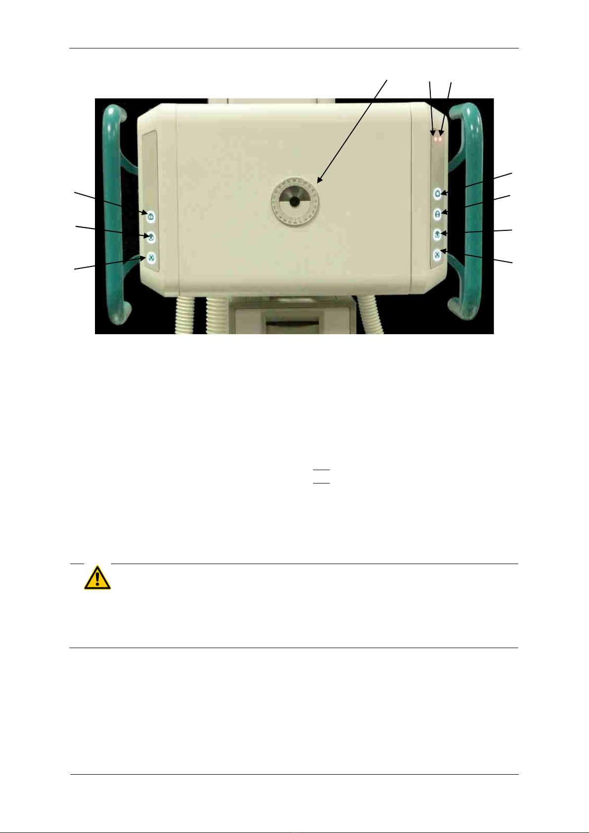
3.4.1 PROGNOST SH
1 Angle indicator for adjusting the X-ray assembly
2 Brake release for horizontal movement of the X-ray floor stand
3 Brake release for rotational movement of the X-ray unit around the horizontal support arm axis
4 Brake release for vertical movement of X-ray tube arm and horizontal movement of X-ray floor stand
5 Brake release for vertical movement of X-ray tube arm and horizontal movement of X-ray floor stand
6 Brake release for movement of X-ray tube assembly around the horizontal support arm axis
7 Brake release for vertical movement of X-ray tube arm
8 Option: Brake release for transversal movement of X-ray tube arm (+230mm)
9 Option: Status-LED orange (if LED is on: X-ray tube arm is not engaged)
10 Option: Status-LED red (if LED on: X-ray flor stand is not engaged)
WARNING!
If th r d LED on th right m mbran k ypad lights up, th X-ray tub carri r
is not ngag d! In this stat no x-rays may b tak n. Th X-ray tub carri r
must first ngag in on of th positions (0 / ± 90° / ± 180°)!
6
5
PRS 500 E
Instructions for use 506 -0-8002
PROTEC GmbH & Co. KG, In den Dorfwiesen 14, 71720 Oberstenfeld, Germany 20 von 47
Operation is performed from the front (operating side) of the X-ray head.
In the case of encompassed handles, the electromagnetic locking of one or more movements can be
released by pressing the keys on the operating unit with the thumb, and the tube head can be moved
to the desired position.
3.4.2 PROGNOST SH TOUCH
1 Touchdisplay of X-ray tube assembly
2 Brake release for horizontal movement of X-ray floor stand
3 Brake release for movement of X-ray tube assembly around the horizontal support arm axis
4 Brake release for vertical movement of X-ray tube arm and horizontal movement of X-ray floor stand
5 Brake release for vertical movement of X-ray tube arm and horizontal movement of X-ray floor stand
6 Brake release for movement of X-ray tube assembly around the horizontal support arm axis
7 Brake release for vertical movement of X-ray tube arm
8 Option: Brake release for transversal movement of X-ray tube arm (+230mm)
9 Option: Status-LED orange (if LED is on: X-ray tube arm is not engaged)
10 Option: Status-LED red (if LED on: X-ray flor stand is not engaged)
WARNING!
If th r d LED on th right m mbran k ypad lights up, th X-ray tub carri r
is not ngag d! In this stat no x-rays may b tak n. Th X-ray tub carri r
must first ngag in on of th positions (0 / ± 90° / ± 180°)!
2
3
1
4
7
6
5
8
9
10
Other manuals for PRS 500 E
2
This manual suits for next models
1
Table of contents
Other Pro-tec Diagnostic Equipment manuals

Pro-tec
Pro-tec PRS 500 F User manual

Pro-tec
Pro-tec PROGNOST XS User manual

Pro-tec
Pro-tec PROGNOST XP User manual

Pro-tec
Pro-tec PROGNOST C User manual

Pro-tec
Pro-tec PRS 500 B User manual

Pro-tec
Pro-tec PRS 500 F User manual

Pro-tec
Pro-tec PRS 500 C User manual

Pro-tec
Pro-tec PRS 500 E Instruction sheet

Pro-tec
Pro-tec PRS 500 E User manual

Pro-tec
Pro-tec PRS 500 B User manual


