AU Tool CT500 User manual
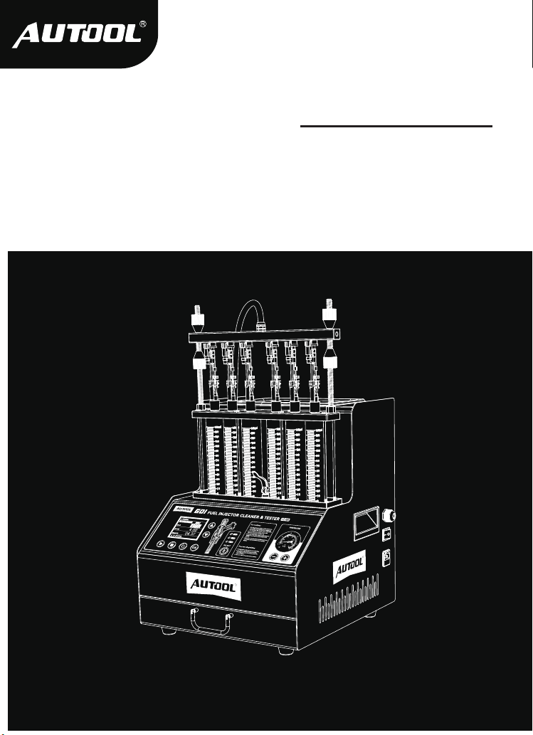
AUTOOL CT500
GDI Fuel Injector Cleaner & Tester
User Manual
用户手册

1
TABLE OF CONTENTS
Cautions .............................................................................................................. 2
Warning........................................................................................................... 2
Product Introduction.......................................................................................... 3
Overview ......................................................................................................... 3
Main functions ................................................................................................. 3
Main features .................................................................................................. 3
Working environment ...................................................................................... 4
Technical parameters ...................................................................................... 4
Product Structure............................................................................................... 5
Structure diagram............................................................................................ 5
Operation panel diagram................................................................................. 6
Operation Process ............................................................................................. 7
Ultrasonic cleaning.......................................................................................... 7
Injector diagnostic ........................................................................................... 8
Storage And Maintenance ................................................................................. 13
Storage............................................................................................................ 13
Maintenance Service.......................................................................................... 14
Maintenance.................................................................................................... 14
Warranty .............................................................................................................. 15
Warranty access.............................................................................................. 15
Disclaimer ....................................................................................................... 15
Return & Exchange Service .............................................................................. 16
Return & Exchange ......................................................................................... 16

2
CAUTIONS
Warning
Since the test device is part of quartz glass, it is easy to break,
so do not place other objects around the equipment to avoid
bumping and breaking.
If there is no digital display after power on, please check
whether the power supply is powered; if so, check whether the
plug is connected firmly, or whether the fuse is blown. If it is not
broken, and the switch is still invalid after pressing the switch
several times intermittently, please contact the manufacturer
and must not disassemble it by yourself, otherwise our compa-
ny will not provide warranty.
When no cleaning agent is added to the ultrasonic tank, it is
strictly prohibited to open the ultrasonic cleaning item to avoid
damage to the ultrasonic system.
Every time the test solution is changed, it must be cleaned up,
and then 1L of new test solution should be added.
The use of unqualified testing agent will cause corrosion of the
oil pump, oil supply pipeline and failure of the pressure gauge.
Using other cleaning agent and testing agent will cause the
equipment surface coating to peel off.
It is strictly forbidden to use kerosene, gasoline or other testing
agent and cleaning agents as testing agent and cleaning
agents for this machine. Otherwise, the “O” ring and pipeline
rubber parts in the equipment will be damaged, causing
leakage.
The cleaning agent and testing agent should not be mixed up.
Before using the instrument, please read this manual careful-
ly for proper operation.

3
Fuel injector diagnostic and cleaning equipment is a mechatronics
product that combines ultrasonic cleaning technology and micro-
computer oil pressure closedloop control cleaning and detection
technology. This product simulates various operating conditions
of the engine, and cleans and inspects the fuel injectors of various
automobiles and motorcycles. This equipment is the necessary
and preferred equipment for the automobile and motorcycle repair
and maintenance industry, research and teaching and training
departments.
PRODUCT INTRODUCTION
Overview
Main
functions
Ultrasonic cleaning:
Ultrasonic cleaning can be performed on single or multiple
injectors at the same time, which can remove the attachments
and internal blockages on the injectors.
Uniformity detection:
To detect the uniformity of the injection volume of each injector.
Atomization observation:
Using the background light, you can observe the spray atomi-
zation situation of the nozzle in a comprehensive and careful
manner.
Tightness test:
It can detect the tightness and dripping of the fuel injector
under high pressure.
Fuel injection volume detection:
It can detect the fuel injection volume of the fuel injection
nozzle under specific working conditions (Such as the same
time and the same number of times).
●
●
●
●
●
Main features Using ultrasonic powerful cleaning technology, strong cleaning
ability.
Using electronic pressure regulating control technology, stable
oil pressure and wide adjustable range.
Use high-quality oil pump to ensure long-term stable use.
●
●
●
Power Supply
Frequency
Relative Humidity
Environment Temperature
AC 110 / 220V ±10%
50HZ ±0.5
<85%
0°C ~ +40°C
External Magnetic Field Strength
No open flames are allowed around
<400A/m
4
Working
environment
Fuel Tank Capacity
Range Of Rotation
PWM Pulse Width
Time Settings
2000ml
0-7500r/min
0~40ms, step 0.1ms
0~10min
Cylinder Volume
Injection Times
System Pressure
Ultrasonic Cleaning Power
140ml
0~9900times, step 100ms
0~0.8Mpa
70W
Technical
parameters
Design with HD color display, makes the operation clear and
easy to learn.
The oil tank liquid level is displayed visually, and the detection
liquid can be recycled.
Bright background light, you can clearly see the various
situations of the fuel injector when it is working.
It has replaceable composite joints suitable for a variety of
vehicle types.
Within the allowable adjustment range, the test time, working
frequency, fuel injection times, shortest switching period, etc.
of the fuel injector can be adjusted arbitrarily.
●
●
●
●
●
5
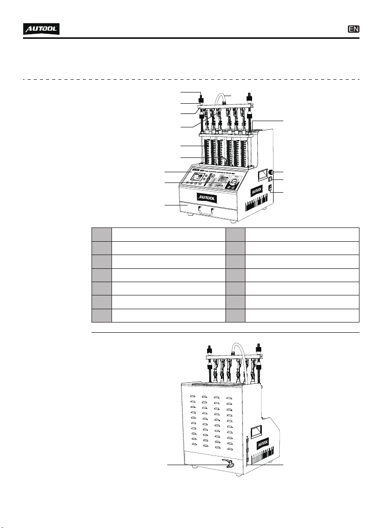
PRODUCT STRUCTURE
Structure
diagram
Operation panel
Portable drawer
7
9
Pressure gauge
Oil outlet pipe
8
10
Ultrasonic cleaning tank
11
Power switch
13
Lock pole
Oil rail
1
3
Lock nut
Top oil inlet connector
2
4
Oil drain handle
6
Signal wire
12
Power socket
14
Glass measuring cylinder
5
15 16
1
2
3
4
5
6
7
8
9
10
12
14
13
11

TFT color screen
Voltage selection
of injectors
1
3
Function buttons
Pressure adjustment
2
4
6
Operation
panel
diagram
Cleaning agent
drain valve
15 Testing agent liquid level
16
1 2 43

7
OPERATION PROCESS
Ultrasonic
cleaning
Ultrasonic cleaning is to use the penetrating and cavitation shock
waves generated when ultrasonic waves propagate in the medium,
and powerfully clean objects with complex shapes, cavities and
pores to completely remove stubborn carbon deposits on the fuel
injector.
Preparation
Remove the fuel injector from the vehicle and check whether
its rubber seal is damaged. If it is damaged, it should be
replaced in time before the cleaning test to avoid leakage
during the test. Then put the fuel injection nozzle into the
cleaning agent, carefully remove the external grease and wipe
it with a soft cloth.
Turn on the power and turn on the power switch on the side of
the main unit.
Put the cleaning bracket in the accessories into the ultrasonic
cleaning tank, and place the wiped fuel injector in the cleaning
bracket positioning hole of the ultrasonic tank.
●
●
●
Methods And Steps
Add an appropriate amount of cleaning agent to the ultrasonic
tank.
Insert the plugs of the drive wires into the injector sockets in
turn. (Special fuel injectors need to be connected with an
adapter cable)
Press the up or down key to select item 01 “Ultrasonic Clean-
ing” , and then press the function setting key to set the working
time.The default working time is 10 minutes, which can be
changed by up and down keys if needed.
Press START button, the system starts to feed pulse signal
and cleaning. After finishing cleaning, take out the injectors
from the ultrasonic bath, wipe the cleaning agent on them with
a soft cloth and prepare for the next item.
●
●
●
●
01 Ultrasonic Cleaning

8
NOTE
During the cleaning process, you can hear the intermittent
(approximately 5 seconds) vibrating sound when you take the
fuel injector out and put it to your ear, so you can judge whether
the fuel injector is working normally.
Ultrasonic cleaning is strictly prohibited when there is no
cleaning agent in the ultrasonic tank to avoid equipment
damage.
Only the ultrasonic cleaning agent dedicated to cleaning the
fuel injection nozzle can be added to the ultrasonic tank, and
other reagents cannot be used instead, otherwise any
malfunctions and damages caused will not be covered by the
warranty.
Injector
diagnostic
This function is to detect the atomization, dripping, blockage, fuel
injection angle status of the fuel injectors and the size and
balance of the fuel injection of each fuel injector at different
speeds.
Preparation
Confirm that the oil drain handle is open, use the funnel in the
accessories to add the test liquid to the equipment through the
glass window, and pay attention to control the flow rate during
the addition to avoid overflow.
Add 1 bottle (about 1000ml) of testing agent each time.
Install the fuel injector.
●
●
●
9
Select the top oil inlet connector from the accessories and
install it into the oil separator.
Install the fuel injector in the forward direction (apply a little
grease on the “O” ring of the fuel injector)
Put the horizontal end of the oil separator and the fuel injector
on the upper plate seat, and tighten the two ends with the
locking rod. Ready to test.
●
●
●
Methods And Steps
02 Idle Speed Test
Confirm that the injector to be tested has been installed
properly and the signal wire has been plugged in.
Select “02 Idle Speed Test”.
Press the function setting key to set the working time and pulse
width.
Press the start button to start work.
●
●
●
●
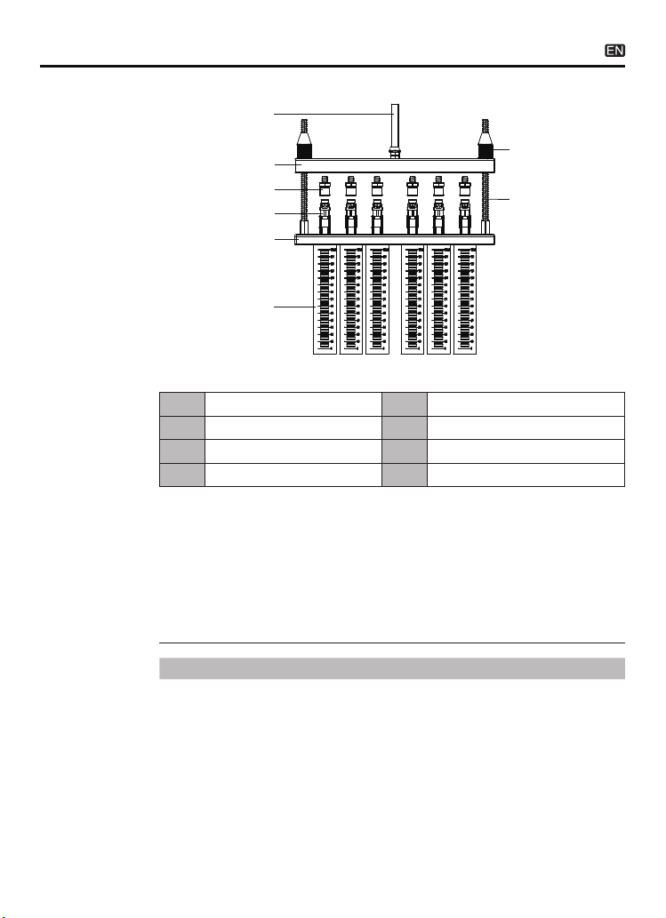
Lock nut7Lock pole8
Oil outlet pipe
Top oil inlet connector
1
3
Oil rail
Injectors
2
4
Glass measuring cylinder
6
Upper plate seat
5
Top-in fuel injector installation diagram
①
②
③
④
⑤
⑥
⑦
⑧

10
Turn the pressure adjustment knob to adjust the pressure to
0.25 ~ 0.3MPa. (In the electronic injection system, the general
oil pressure works at 0.25~ 0.3MPa)
The working time gradually decreases. When it is 0, the system
automatically stops.
●
●
NOTE
The fuel pressure, working time and pulse width are automati-
cally set by the system. The time system defaults to 10s as a
cycle period, and the user does not need to set it separately.
The system will automatically and continuously cycle three
times to simulate the working condition and fuel injection
volume of the fuel injector when the engine is accelerating
uniformly.
03 Medium Speed Test
Select “03 Medium Speed Test”.
Press the start button.
The rest of the operation steps are consistent with item 02.
●
●
●
04 High Speed Test
Select “04 High Speed Test”.
Press the start button.
The rest of the operation steps are consistent with item 02.
●
●
●
05 Accelerating Test
Select “05 Accelerating Test”.
Press the start button.
●
●
06 Variable Speed Test
Select “06 Variable Speed Test”.
Press the start button.
●
●
NOTE
The fuel pressure, working time and pulse width are automati-
cally set by the system. The time system defaults to a cycle of

11
NOTE
The pulse width system defaults to 3ms, no need to set it
again.
Whether the fuel injection nozzle is dripping and leaking when
the simulated oil pressure is 0.3Mpa.
10s, and the user does not need to set it separately.
The system will automatically and continuously cycle three
times to simulate the working condition and fuel injection
volume of the fuel injector when the engine is idling, medium
speed, and high speed.
07 Leakage Test
Select “07 Leakage Test”.
Press the function setting key to set the working time. (Gener-
ally set to 1 minute)
The rest of the operation steps are consistent with item 02.
●
●
●
DESCRIPTION
Simulate the working conditions and fuel injection volume of
the engine when the fuel injection nozzle works for a certain
number of times when the engine is idling.
08 Idling Spray Value Test
Select “08 Idling Spray Value Test”.
Press the function setting key to set the pulse width and pulse
times. (Generally set to 2000 times)
The rest of the operation steps are consistent with item 02.
●
●
●
10 High Speed Spray Value Test
Select “10 High Speed Spray Value Test”.
The rest of the operation steps are consistent with item 08.
●
Select “09 Medium Speed Spray Value Test”.
The rest of the operation steps are consistent with item 08.
●
●
●
09 Medium Speed Spray Value Test

12
NOTE
Flow Balance Test
The flow balance test shall be carried out at different speeds.
When the liquid level in the measuring cylinder is 2/3 of the
measuring cylinder, pause or stop work to observe the balance
of the fuel injection volume. The deviation of the fuel injection
volume of all fuel injection nozzles on a vehicle should not
exceed 2%. Or refer to the relevant technical manual of the fuel
injector to judge the flow balance of the fuel injector.
Observation of Fuel Injection Shape
Observe whether the fuel injection shapes and angles of all
fuel injection nozzles on the same car are uniform at various
speeds. At the same time, you can adjust the opening pulse
width of the fuel injection nozzle to check whether the minimum
opening pulse width of the fuel injection nozzle is consistent.
Leak Detection Test
The leak detection test is to detect the tightness of the injector
needle valve under the high pressure of the system. (Observe
the tightness of the fuel injector, generally there should be no
leakage within one minute)
11 Reverse Flushing
Press the item selection up and down keys to select “11
Reverse Flushing”, and install the injectors in the opposite
direction for cleaning.
●
12 No-disassembly Cleaning
Select “12 No-disassembly Cleaning”.
Cleaning time can be set to a maximum of 20 minutes. Please
connect to various special parts that can clean the combustion
chamber or throttle.
●
●
13 Pulse Injection Test
Select “13 Pulse Injection Test”.
Press function setting key to set pulse width and pulse times.
Other steps are the same as in item 02.
●
●
●

13
STORAGE AND MAINTENANCE
Storage Turn off the power and unplug the power plug.
Put all connectors back into the accessory box for storage.
Drain the ultrasonic cleaning agent. Wipe the equipment clean
with a dry soft cloth.
If the machine needs to be stored for a long time, discharge the
testing agent into a bottle and seal it.
●
●
●
●
Replacement of Test Agent
When the test agent is used for a period of time, a lot of impuri-
ties will accumulate, and the agent containing dirt cannot be
used, otherwise it will easily block the fuel injector. When
replacing the agent, first open the testing agent drain valve to
empty the tank, and then inject a little testing agent to clean the
interior of the tank. After cleaning, drain the fuel tank again and
then pour 1L of new testing agent into the tank.
Fuse Replacement
There is a square box marked with a fuse on the power socket
on the left side of the device, and the fuse can be seen by
opening the box. If it is blown, replace it with a new one.
●
●
14 Wide Pulse Injection Test
Press the up or down key to select “Item 14 Wide Pulse Injec-
tion Test”.
Other steps are the same as in item 13.
●
●
15 Continuous Injection Test
Press the up or down key to select “Item 15 Continuous Injec-
tion Test”.
Press function setting key to set working time. (Recommended
working time is less than 30s)
Other steps are the same as in item 02.
●
●
●

14
Be careful not to rub the product against rough surfaces or
wear the product, especially the sheet metal housing.
Please regularly check the product parts that need to be
tightened and connected. If found loose, please tighten it in
time to ensure the safe operation of the equipment. The exter-
nal and internal parts of the equipment in contact with various
chemical media should be frequently treated with anti-corrosion
treatment such as rust removal and painting to improve the
corrosion resistance of the equipment and extend its service
life.
Comply with the safe operating procedures and do not
overload the equipment. The safety guards of the products
are complete and reliable.
Unsafe factors are to be eliminated in time. The circuit part
should be checked thoroughly and the aging wires should be
replaced in time.
Adjust the clearance of various parts and replace worn
(broken) parts. Avoid contact with corrosive liquids.
When not in use, please store the product in a dry place. Do
not store the product in hot, humid, or non-ventilated places.
Our products are made of long-lasting and durable materials, and
we insist on perfect production process. Each product leaves the
factory after 35 procedures and 12 times of testing and inspec-
tion work, which ensures that each product has excellent quality
and performance.
To maintain the performance and appearance of the product, it is
recommended that the following product care guidelines be read
carefully:
●
●
●
●
●
●
MAINTENANCE SERVICE
Maintenance

15
WARRANTY
The repair or replacement of products is determined by the
actual breakdown situation of product.
It is guaranteed that AUTOOL will use brand new component,
accessory or device in terms of repair or replacement.
If the product fails within 90 days after the customer receives
it, the buyer should provide both video and picture, and we will
bear the shipping cost and provide the accessories for the
customer to replace it free of charge. While the product is
received for more than 90 days, the customer will bear the
appropriate cost and we will provide the parts to the customer
for replacement free of charge.
The product is not purchased through official or authorized
channels.
The product breakdown because the user does not follow
product instructions to use or maintain the product.
From the date of receipt, we provide a three-year warranty for the
main unit and all the accessories included are covered by a
one-year warranty.
We AUTOOL pride ourselves on superb design and excellent
service. It would be our pleasure to provide you with any further
support or services.
All information, illustrations, and specifications contained in this
manual, AUTOOL resumes the right of modify this manual and the
machine itself with no prior notice. The physical appearance and
color may differ from what is shown in the manual, please refer to
the actual product. Every effort has been made to make all
descriptions in the book accurate, but inevitably there are still
inaccuracies, if in doubt, please contact your dealer or AUTOOL
after-service centre, we are not responsible for any consequences
arising from misunderstandings.
●
●
●
●
●
These conditions below shall not be in warranty range
Warranty
access
Disclaimer

16
If you are an AUTOOL user and are not satisfied with the
AUTOOL products purchased from the online authorized
shopping platform and offline authorized dealers, you can
return the products within seven days from the date of receipt;
or you may exchange it for another product of the same value
within 30 days from the date of delivery.
Returned and exchanged products must be in fully saleable
condition with documentation of the relevant bill of sale, all
relevant accessories and original packaging.
AUTOOL will inspect the returned items to ensure that they
are in good condition and eligible. Any item that does not pass
inspection will be returned to you and you will not receive a
refund for the item.
You can exchange the product through the customer service
center or AUTOOL authorized distributors; the policy of return
and exchange is to return the product from where it was
purchased. If there are difficulties or problems with your return
or exchange, please contact AUTOOL Customer Service.
●
●
●
●
RETURN & EXCHANGE SERVICE
Return &
Exchange
China
Oversea Zone
E-mail
Facebook
YouTube
400-032-0988
+86 0755 23304822
aftersale@autooltech.com
https://www.facebook.com/autool.vip
https://www.youtube.com/c/autooltech
Table of contents
Other AU Tool Test Equipment manuals

AU Tool
AU Tool CT400 User manual

AU Tool
AU Tool BT460 User manual

AU Tool
AU Tool BT 260 User manual

AU Tool
AU Tool SPT101 User manual

AU Tool
AU Tool BT760 User manual

AU Tool
AU Tool BT-660 User manual

AU Tool
AU Tool BT70 User manual

AU Tool
AU Tool BT360 User manual

AU Tool
AU Tool BT-660 User manual

AU Tool
AU Tool BT160 User manual


Popular Test Equipment manuals by other brands

Pace Technologies
Pace Technologies OMEGA SRT-15/150 instruction manual

Ripley
Ripley MILLER DLS 650 user guide

Gas Measurement Instruments
Gas Measurement Instruments 67130 Quick Operating Instructions

IDEAL Networks
IDEAL Networks SignalTEK NT manual

BTE Technologies
BTE Technologies Multi-Cervical Unit user manual

Ponovo
Ponovo T500 Series Hardware operation manual


