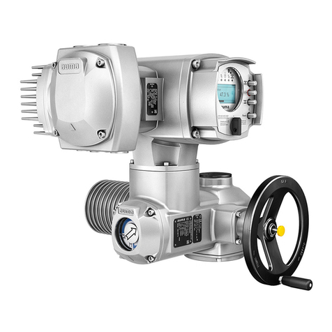
AUMA PROFOX PF-M25X User manual

PROFOX actuators
PF-M25(X) –PF-M100(X)
PF-Q80(X) –PF-Q600(X)
Parameter and functionsManual

Read operation instructions first.
●Observe safety instructions.
Purpose of the document:
This document contains information for the commissioning, operation and maintenance staff.It is intended to
support local device operation and setting modifications.
Table of contents Page
41. Safety instructions................................................................................................................. 41.1. Prerequisites for the safe handling of the product 41.2. Range of application 41.3. Warnings and notes 41.4. References and symbols
52. Service software.....................................................................................................................
63. Operation................................................................................................................................ 63.1. Manual operation 63.2. Motor operation 63.2.1. Actuator operation via push buttons 73.2.2. Actuator operation via AUMA Assistant App 83.2.3. Actuator operation from Remote
114. Device menu........................................................................................................................... 114.1. Diagnostics 114.1.1. Detailed diagnostics 114.1.1.1. Bluetooth 114.1.1.2. Interface 114.1.1.3. Position sensor 124.1.1.4. Torque values MWG 124.1.1.5. Positioner 124.1.1.6. Operation mode 134.1.1.7. Profibus DP1 134.1.1.8. Details Profibus 134.1.1.9. Modbus MD1 144.1.1.10. Modbus MD2 144.1.1.11. Details Modbus 154.1.2. Operational info collection 154.1.2.1. Operational information total / Operational information 174.1.2.2. Event report 184.1.2.3. Characteristics 194.1.2.3.1 Torque profiles 204.1.2.4. Maintenance 204.1.2.5. Device temperatures 214.2. Configuration 214.2.1. Operation mode 224.2.2. Indication 224.2.2.1. Display 244.2.2.2. Actuator internal control unit 264.2.3. Type of seating 274.2.4. Torque switching
2
PROFOX actuators
Table of contents

304.2.5. Positioner 374.2.6. Speed functions 384.2.6.1. Speed reduction 384.2.6.2. Speed adaptation prior to end position 394.2.6.3. Soft start and soft stop 404.2.6.4. Speed setpoint 424.2.7. Intermediate positions 424.2.7.1. Pivot points 434.2.7.2. Signal behaviour 434.2.7.3. Hysteresis 444.2.8. Failure behaviour 474.2.9. Timer function 484.2.10. EMERGENCY behaviour 524.2.11. Duty type monitoring 524.2.12. I/O interface 534.2.12.1. Digital inputs 554.2.12.2. Analogue inputs 564.2.12.3. Digital outputs 594.2.12.4. Analogue outputs 614.2.13. Fieldbus 614.2.13.1. Profibus 634.2.13.2. Modbus 654.2.13.3. Combination of fieldbus interface and I/O interface 664.2.13.4. Auto change-over I/O 674.2.14. Switchgear 674.2.15. Monitoring functions 674.2.15.1. Voltage monitoring 684.2.15.2. Battery monitoring 684.2.15.3. Temperature monitoring 684.2.15.4. Torque warning 684.2.15.5. Motion detector 694.2.15.6. Reaction monitoring 704.2.15.7. Operating time monitoring 714.2.16. Bluetooth interface 734.2.17. Service interface 744.2.18. Configuration of signals 804.2.19. Application functions 804.2.19.1. Enabling 804.2.19.2. Activation 814.3. Device ID 824.4. Service functions
835. Corrective actions.................................................................................................................. 835.1. Faults during commissioning 835.2. Fault indications and warning indications 865.3. Not ready REMOTE
876. Thermal fuse...........................................................................................................................
90Index........................................................................................................................................
92Parameter index.....................................................................................................................
3
PROFOX actuators Table of contents

1. Safety instructions
1.1. Prerequisites for the safe handling of the product
Information on safe handling of the product are available with the respective operation
instructions.The references specified must imperatively heeded.
1.2. Range of application
AUMA actuators are designed for the operation of industrial valves.
Other applications require explicit (written) confirmation by the manufacturer.
No liability can be assumed for inappropriate or unintended use.
Observance of these instructions and the operation instructions is considered as
part of the device's designated use.
1.3. Warnings and notes
The following warnings draw special attention to safety-relevant procedures in these
operation instructions, each marked by the appropriate signal word (DANGER,
WARNING, CAUTION, NOTICE).
Indicates an imminently hazardous situation with a high level of risk. Failure
to observe this warning results in death or serious injury.
Indicates a potentially hazardous situation with a medium level of risk.Failure
to observe this warning could result in death or serious injury.
Indicates a potentially hazardous situation with a low level of risk. Failure to
observe this warning could result in minor or moderate injury. May also be
used with property damage.
Potentially hazardous situation. Failure to observe this warning could result
in property damage. Is not used for personal injury.
Safety alert symbol warns of a potential personal injury hazard.
The signal word (here: DANGER) indicates the level of hazard.
1.4. References and symbols
The following references and symbols are used in these instructions:
Information The term Information preceding the text indicates important notes and information.
Symbol for CLOSED (valve closed)
Symbol for OPEN (valve open)
Via the menu to parameter
Describes the menu path of AUMA Assistant App or the AUMA CDT software to the
parameter/process data on the basis of the display texts.Display texts, parameters
and process data are highlighted in grey: Example.In addition, in most cases, the
object ID of the display texts (DIS), the parameter (PRM) or the process date (PZD)
is indicated.These object IDs can be shown in AUMA CDT software via “File”and
“Options”.The search function of AUMA CDT software (Strg + F) can be used to
quickly find the display texts, parameters and process data.
➥Result of a process step
Describes the result of a preceding process step.
4
PROFOX actuators
Safety instructions

2. Service software
Using the AUMA CDT software for Windows-based computers (notebooks or tablets)
and the AUMA Assistant App, actuator data can be uploaded and read, settings
can be modified and stored.The connection between computer and AUMA actuator
is established wireless via Bluetooth interface.With the AUMA Cloud, we provide
an interactive platform to collect and assess e.g.detailed device data of all actuators
within a plant.
Figure 1: Communication via Bluetooth
AUMA CDT AUMA CDT is a user-friendly setting and operation program for AUMA actuators.
Connection between computer (notebook, tablet) and actuator is wireless via
Bluetooth interface.
AUMA CDT software can be downloaded free of charge from our website
www.auma.com.
AUMA Cloud
The AUMA Cloud is the driving element of the digital AUMA world, acting as
interactive platform for efficient maintenance of AUMA actuators at moderate cost.
The AUMA Cloud collects all device data of all actuators within one site and provides
a clear overview at a glance.Detailed analysis provides valuable information on
potential maintenance requirements.Additional functions foster smooth asset
management.
AUMA Assistant App The AUMA Assistant App enables commissioning, configuration and diagnostics of
AUMA actuators via Bluetooth using either smartphone or tablet.
The AUMA Assistant App can be downloaded free of charge from the Play Store
(Android) or App Store (iOS).
Figure 2: Link to AUMA Assistant App
5
PROFOX actuators Service software

3. Operation
3.1. Manual operation
The following description applies for clockwise closing standard version.
Separate instructions are available for counterclockwise special version.
The handwheel allows actuator operation even in case of power failure. Handwheel
operation is only provided for occasional manual valve operation.
The handwheel does not rotate during motor operation. Change-over from motor
operation to manual operation is not required.
1. Close valve:Turn handwheel clockwise.
➥Drive shaft (valve) turns clockwise in direction CLOSE.
2. Open valve:Turn handwheel counterclockwise.
➥Drive shaft (valve) turns counterclockwise in direction OPEN.
Information Turning the handwheel during motor operation extends or reduces the operating
time, depending on the direction of rotation.
3.2. Motor operation
Valve damage due to incorrect settings!
→Check the parameters configured in the factory prior to electrical actuator oper-
ation.
→In case of deviations, adapt the parameters according to the valve and application
requirements.
Frozen valves when used in low temperatures below –15 °C
→Recommendation: Activate excessive torque (parameter PRM_5718 ) to allow
using a peak torque of up to 127 % of the max. tripping torque when leaving
the end position.
3.2.1. Actuator operation via push buttons
The actuator can be locally operated by means of four push buttons.
Information To perform actuator operation via push buttons, please connect to power supply.
6
PROFOX actuators
Operation

Figure 3: Push button (example of I/O interface)
[1] Set end position OPEN push button
[2] Set operation in direction OPEN push button
[3] Set operation in direction CLOSE push button
[4] Set end position CLOSED push button
[5] LED
Risk of passing set end positions!
→During operation in directions OPEN/CLOSE, the actuator stops when reaching
the set end position.When pressing again the push button, the actuator runs
until reaching a mechanical stop (end stop of the actuator or the valve) or passes
the end position when releasing the push button.
1. Run actuator in direction OPEN: Hold down button [2].
➥The LED flashes in green during operation in direction OPEN.
2. Run actuator in direction CLOSE: Hold down button [3].
➥The LED flashes in red during operation in direction CLOSE.
3.2.2. Actuator operation via AUMA Assistant App
Functions Alternatively, actuator operation is possible using the “AUMA Assistant”smartphone
Appor the AUMACDTsoftware.Thefollowing tableshowsan overviewof themenus
of the AUMA Assistant App and the AUMA CDT software.
DescriptionMenu
Display of all available warnings and faults including
respective details.
Actuator diagnostics and detailed diagnostics
Diagnostics
Operation in direction of end positions
Resetting the fault log
Operation function
Setting the positions for end positions CLOSED and
OPEN
Setting end positions
Device designation
Order number, serial number
Device ID
Configuration of all parameters
Configuration
Factory settings
Rebooting the actuator
Service functions
7
PROFOX actuators Operation

User level User level (1), (2), (3), ...defines which menu items or parameters can be displayed
or modified by the active user.
6 different users/user levels are available.User level (1), (2), (3), ...is indicated in
the top display row.
Figure 4: User level display (example user level 4)
Password A specific password is assigned to each user level and allows different actions.The
password must comprise 6 characters.
Table 1: User level and password
User levels and authorisations
Authorisation/passwordUser (user level)
Verify settings
No password required
Observer (1)
Change configuration parameters (low level)
Factory password: 000000
Operator (2)
Reserved for future use
Maintenance (3)
Change configuration parameters (high level)
e.g.type of seating, assignment of output contacts
Factory password: 000000
Specialist (4)
Service staff
Change configuration parameters (service level)
Service (5)
AUMA administrator
AUMA (6)
Unauthorised access due to insecure password!
→We recommend changing the password during initial commissioning.
3.2.3. Actuator operation from Remote
Risk of immediate actuator operation when connecting to mains!
Risk of death, severe injury or damage to valve.
→Check operation signals and operation behaviour prior to switching on the mains
voltage.
→Ensurethat the tripping conditions forthe failurebehaviour are not fulfilledwhen
switching on.
→Ensure that the tripping conditions for the EMERGENCY behaviour are not ful-
filled when switching on.
Operation mode REMOTE setting
Operation mode REMOTE is the preliminary condition for actuator control via binary
signals, analogue signals or via fieldbus.
The operation mode can be activated via AUMA Assistant App or AUMA CDT
software:
AUMA Assistant App DIS_53 Configuration
DIS_2919 Operation mode
PRM_5535 Selector
Or directly via the Remote operation menu in DIS_2250 Operation function.
Default setting: Operation mode = REMOTE
AUMA CDT DIS_53 Configuration
DIS_2919 Operation mode
8
PROFOX actuators
Operation

PRM_5535 Selector
Or directly via the tool bar in the “Device”tab in PRM_5535 Selector or Remote
control.
Default setting: Operation mode = REMOTE
Information The actuator only reacts to the currently selected command source. However, the
command source can be changed during running operation.The OPEN/CLOSE
operation is usually performed via the digital inputs.The setpoint control (e.g.for
modulating duty) can only be performed via the analogue inputs or the fieldbus.
Change-over between OPEN-CLOSE control and setpoint control
For PROFOX actuators, it is possible to select between OPEN - CLOSE control
(REMOTE OPEN-CLOSE) and setpoint control (REMOTE SETPOINT).
For the change-over, a digital input must be available and configured for the PZD_22
MODE signal.
●PZD_22 MODE input = high level (default:+ 24V DC) = Remote OPEN-CLOSE
Control is made via binary OPEN, STOP, CLOSE commands.
●PZD_22 MODE input = low level (0 V or input open) = REMOTE SETPOINT
Control takes place via an analogue signal (e.g. 0/4 –20 mA).
Change-over between fieldbus control and OPEN-CLOSE via I/O signals (for
actuators with fieldbus interface)
As standard, the actuator is supplied with fieldbus and digital signals.A digital input
is used to define which source is active, this means whether the actuator is controlled
via fieldbus or via I/O signals. It is not possible to use both sources to active
simultaneously.The PRM_926 Signal DIN 3 signal is assigned to PZD_275 I/O
interface as factory setting:
Not live (= 0V) means that control is made from REMOTE via fieldbus.
Live (= 24V) means that control is made from REMOTE via binary I/O signals.
Commands for the operation function:
OPEN/CLOSE operation commands can be issued via fieldbus or a setpoint can be
sent for any position.Change-over is made via the PZD_332 Fieldbus SETPOINT
command.
●Setpoint control:
Fieldbus SETPOINT command bit = 1 = REMOTE SETPOINT
The actuator reacts to the setpoint E1 transmitted via the fieldbus.
●OPEN - CLOSE control:
Fieldbus SETPOINT command bit = 0 = REMOTE OPEN-CLOSE
Actuator can be operated via Fieldbus OPEN/Fieldbus CLOSE command bits
in direction OPEN or CLOSE.
Configuration of digital input
Required user level:Specialist (4).
DIS_53 Configuration
DIS_139 I/O interface
DIS_116 Digital inputs
Example: Use Signal DIN 1 input for change-over:
Parameters: PRM_873 Signal DIN 1
Setting value: MODE
Setting value: I/O interface
EMERGENCY operation
An EMERGENCY operation is triggered by a signal at EMERGENCY input or the
Fieldbus EMERGENCY command bit.The actuator moves to a predefined
9
PROFOX actuators Operation

EMERGENCY position (i.e.end position OPEN or end position CLOSED). During
EMERGENCY operation, the actuator does not react to other operation commands
such as Remote OPEN/Remote CLOSE, Remote SETPOINT, Fieldbus
OPEN/Fieldbus/CLOSE or Fieldbus SETPOINT.
10
PROFOX actuators
Operation

4. Device menu
Menus depend on the firmware version, the user level and the equipment of
the actuator!
→Update the actuator with AUMA CDT or via the actuator’s USB interface, if re-
quired.
→Login with the respectively required user level.
→For missing menus/function/parameters, contact the AUMA Service.
4.1. Diagnostics
Diagnostics comprise of information on the device and on device sub-assemblies
for support during commissioning, maintenance or corrective action.
4.1.1. Detailed diagnostics
4.1.1.1. Bluetooth
The menu is only visible if the Bluetooth function (parameter PRM_2591 Bluetooth
interface) is activated. For enabling and activation of functions, refer to chapter
Application functions.
DIS_2249 Diagnostics
DIS_22 Detailed diagnostics
DIS_244 Bluetooth
The following states can be checked via diagnostics:
Table 2: DescriptionIndicationID
Information on identification of the actuator
within the plant (e.g.KKS (Power Plant Classi-
fication System)
DesignationPRM_1165
Bluetooth address of controls
Bluetooth addressPRM_2188
Activate/deactivate Bluetooth interface
Bluetooth interfacePRM_2591
Bluetooth signal intensity in dbm
Bluetooth signal intensity in dbmPRM_1983
4.1.1.2. Interface
DIS_2249 Diagnostics
DIS_22 Detailed diagnostics
DIS_239 Interface
This diagnostics can be used to check the following status:
Table 3: DescriptionIndicationID
Status of the interface
Interface statusDIS_730
4.1.1.3. Position sensor
DIS_2249 Diagnostics
DIS_22 Detailed diagnostics
DIS_2454 Position sensor
The following states can be checked via diagnostics:
11
PROFOX actuators Device menu

Table 4: DescriptionIndicationID
Value of end position OPEN
End position OPEN valuePRM_5538
Value of end position CLOSED
End position CLOSED valuePRM_5539
End positions of hysteresis
Hysteresis end positionsPRM_5395
Absolute position
Absolute positionPRM_1954
Relative position
Relative positionPRM_1956
Actual position
Actual positionPRM_709
The indication correspond to the incremental values of the digital position sensor.
4.1.1.4. Torque values MWG
DIS_2249 Diagnostics
DIS_22 Detailed diagnostics
DIS_1033 Torque values MWG
The following states can be checked via diagnostics:
Table 5: DescriptionIndicationID
Scaling 0.1 torque value OPEN (sync) in Nm
Scaling 0.1 torque value OPEN (sync) in
Nm
PZD_2077
Scaling 0.1 torque value CLOSE (sync) in Nm
Scaling 0.1 torque value CLOSE (sync)
in Nm
PZD_2078
4.1.1.5. Positioner
DIS_2249 Diagnostics
DIS_22 Detailed diagnostics
DIS_613 Positioner
The following states can be checked via diagnostics:
Table 6: DescriptionIndicationID
Setting the adaptive behaviour
Adaptive behaviourPRM_84
Set setpoint position
SetpointPZD_1117
Set actual position
Actual positionPZD_709
Set outer dead band
Outer dead bandPZD_659
Set outer dead band OPEN
Outer dead band OPENPZD_1030
Set outer dead band CLOSE
Outer dead band CLOSEPZD_1031
Set inner dead band OPEN
Inner dead band OPENPZD_1032
Set inner dead band CLOSE
Inner dead band CLOSEPZD_1033
4.1.1.6. Operation mode
The menu is only visible if duty type monitoring (parameter PRM_2121 Duty type
monitoring) is activated. For enabling and activation of functions, refer to chapter
Application functions.
DIS_2249 Diagnostics
DIS_22 Detailed diagnostics
DIS_593 Operation mode
The following states can be checked:
Table 7: DescriptionIndicationID
On time
On timePZD_488
Number of motor starts / h
Number of motor starts/hPZD_489
12
PROFOX actuators
Device menu

4.1.1.7. Profibus DP1
This diagnostic provides information on the current status of the Profibus
sub-assemblies.
DIS_2249 Diagnostics
DIS_22 Detailed diagnostics
DIS_240 Profibus DP1
The following states can be checked:
Table 8: DescriptionIndicationID
Activity of fieldbus available on channel 1
Channel 1 activityPZD_613
Channel 1 is currently used to exchange data
(DataEx)
Channel 1 DataExPZD_657
Profibus DP channel 1;current slave address
DP1 slave addressPZD_958
Profibus DP channel 1;baud rate
DP1 baud ratePZD_578
Profibus DP channel 1;status of the watchdog
DP1 watchdog statusPZD_576
Profibus DP channel 1;Profibus status
DP1 Profibus statusPZD_577
Profibus DP channel 1;Global Control Clear
DP1 Global Control ClearPZD_580
Profibus DP channel 1;Data length 0
DP1 data length 0PZD_579
Profibus DP channel 1;Global Control Freeze
DP1 Global Control FreezePZD_581
Profibus DP channel 1;Global Control Sync
DP1 Global Control SyncPZD_582
DP1 config. Data
DP1 config. dataPZD_1126
Refer to the Manual “PROFOX device integration Profibus DP”, AUMA document
Y009.290 for a detailed description of the displays contained in these menus.
4.1.1.8. Details Profibus
This diagnostics provides information on the current state of the Profibus
sub-assemblies.
DIS_2249 Diagnostics
DIS_22 Detailed diagnostics
DIS_602 Details Profibus
Table 9: DescriptionIndicationID
DP-V1 control active
DP-V1 controlPZD_737
DP-V1 connection active
DP-V1 connection activePZD_738
Profibus identification number
Profibus Ident no.PRM_3006
DP-V1 function in parameter telegram
DP-V1 (SetPrm)PZD_744
Signalling of alarms in parameter telegram
Alarms (SetPrm)PZD_746
Refer to the Manual “PROFOX device integration Profibus DP”, AUMA document
Y009.290 for a detailed description of the displays contained in these menus.
4.1.1.9. Modbus MD1
This diagnostics provides information on the current status of the Modbus
sub-assembly for channel 1.
DIS_2249 Diagnostics
DIS_22 Detailed diagnostics
DIS_241 Modbus MD1
The following states can be checked:
13
PROFOX actuators Device menu

Table 10: DescriptionIndicationID
Bus communication available on channel 1
Channel 1 activityPZD_613
Channel 1 is in the data exchange state
(DataEx)
Channel 1 DataExPZD_657
Modbus channel 1;current slave address
MD1 slave addressPZD_956
Current baud rate of Modbus interface
Baud ratePZD_847
Bus Message Count
Bus Message CountPZD_993
Bus Communication Error Count
Bus Communication Error CountPZD_994
Slave Exception Error Count
Slave Exception Error CountPZD_995
Slave Message Count
Slave Message CountPZD_996
Slave No Repsonse Count
Slave No Repsonse CountPZD_997
Slave NAK Count
Slave NAK CountPZD_998
Slave Busy Count
Slave Busy CountPZD_999
Bus Character Overrun Count
Bus Character Overrun CountPZD_1000
Parity Error Count
Parity Error CountPZD_1001
Refer to the Manual “PROFOX device integration Modbus RTU”, AUMA document
Y009.291 for a detailed description of the displays contained in these menus.
4.1.1.10. Modbus MD2
This diagnostics provides information on the current status of the Modbus
sub-assembly for channel 2.
DIS_2249 Diagnostics
DIS_22 Detailed diagnostics
DIS_775 Modbus MD2
The following states can be checked:
Table 11: DescriptionIndicationID
Bus communication available on channel 2
Channel 2 activityPZD_614
Channel 2 is in the data exchange state
(DataEx)
Channel 2 DataExPZD_658
Modbus channel 2;current slave address
MD2 slave addressPZD_957
Current baud rate of Modbus interface
Baud ratePZD_847
Bus Message Count
Bus Message CountPZD_1002
Bus Communication Error Count
Bus Communication Error CountPZD_1003
Slave Exception Error Count
Slave Exception Error CountPZD_1004
Slave Message Count
Slave Message CountPZD_1005
Slave No Repsonse Count
Slave No Repsonse CountPZD_1006
Slave NAK Count
Slave NAK CountPZD_1007
Slave Busy Count
Slave Busy CountPZD_1008
Bus Character Overrun Count
Bus Character Overrun CountPZD_1009
Parity Error Count
Parity Error CountPZD_1010
Refer to the Manual “PROFOX device integration Modbus RTU”, AUMA document
no.Y009.291 for a detailed description of the displays contained in these menus.
4.1.1.11. Details Modbus
This diagnostics provides information on the current state of the Profibus
sub-assemblies.
DIS_2249 Diagnostics
DIS_22 Detailed diagnostics
DIS_777 Details Modbus
14
PROFOX actuators
Device menu

Table 12: DescriptionIndicationID
Channel 1 is the active operation command
channel.
Channel 1 activePZD_604
Channel 2 is the active operation command
channel.
Channel 2 activePZD_605
Refer to the Manual “PROFOX device integration Modbus RTU”, AUMA document
Y009.291 for a detailed description of the displays contained in these menus.
4.1.2. Operational info collection
4.1.2.1. Operational information total / Operational information
The operating data provide information on parameters like running time, number of
starts or, for example, the number of torque faults
The analysis of this data provides valuable information regarding the optimisation of
both actuator and valve.When using this information purposefully, actuator and valve
will be carefully operated, e.g. through appropriate parameter setting. In case of
faults, the logging of operating data allows for quick fault diagnostic.
Two counters are available, a lifetime counter and a resettable counter.
DIS_2249 Diagnostics
DIS_1231 Operational info collection
DIS_183 Operational information total
DIS_188 Operational information
Description of the displays:
DIS_183 Operational information total = Lifetime counter
DIS_188 Operational information = Counter can be reset to 0
Table 13: Operational info total
DescriptionIndicationID
Motor running time throughout the lifetime
Motor running timePRM_495
Max. running time / h
Max. running time /hPRM_5227
Operating hours counter: Number of hours
during which the actuator was supplied with
voltage.
Operating hoursPRM_5068
Number of motor starts throughout the lifetime
Motor startsPRM_496
Max. starts / h
Max. starts/hPRM_5226
Mean torque value
Mean torque valuePRM_5213
Number of torque faults CLOSE throughout
the lifetime
Torque fault CLOSEPRM_501
Number of torque faults OPEN throughout the
lifetime
Torque fault OPENPRM_502
NumberoftorquewarningsCLOSEthroughout
the lifetime
Number of torque warnings CLOSE dur-
ing the lifetime
PRM_4704
Number of torque warnings OPEN throughout
the lifetime
Number of torque warnings OPEN during
the lifetime
PRM_4703
Sum of torque warnings OPEN and CLOSE
throughout the lifetime
Number of torque warnings
OPEN+CLOSE during the lifetime
PRM_5401
Counter for excessive torque (factory)
Counter for excessive torque (factory)PRM_5621
Number of limit switch CLOSE trippings
throughout the lifetime
Limit switch CLOSE trippingsPRM_498
Number of limit switch OPEN trippings
throughout the lifetime
Limit switch OPEN trippingsPRM_500
Number of torque switch CLOSE trippings
throughout the lifetime
Torque switch CLOSE trippingsPRM_497
15
PROFOX actuators Device menu

DescriptionIndicationID
Number of torque switch OPEN trippings
throughout the lifetime
Torque switch OPEN trippingsPRM_499
Sum of all time fractions during which an on-
time warning has been signalled
On time warning 1PRM_505
Max.time span during which an on time warn-
ing was indicated.
On time warning 2PRM_506
Numberofsystemstarts throughout the lifetime
Number of system startsPRM_507
Maximum temperature of controls
Max. temperature controlsPRM_4765
Minimum temperature of controls
Min. temperature controlsPRM_4766
Average temperature logic (factory)
Average temperature logic (factory)PRM_5424
Average value operating time OPEN (factory)
Average value operating time OPEN
(factory)
PRM_5436
Average value operating time CLOSE (factory)
Average value operating time CLOSE
(factory)
PRM_5442
Warning time excessive logic temperature
(factory)
Warning time excessive logic temperature
(factory)
PRM_5457
Warning time insufficient logic temperature
(factory)
Warning time insufficient logic temperat-
ure (factory)
PRM_5458
Last operation time in direction CLOSE (fact-
ory)
Last operation time in direction CLOSE
(factory)
PRM_5475
Last operating time in direction OPEN (factory)
Last operating time in direction OPEN
(factory)
PRM_5476
Last operating time reference operation in dir-
ection CLOSE (factory)
Last operating time reference operation
in direction CLOSE (factory)
PRM_5479
Last operating time reference operation in dir-
ection OPEN (factory)
Last operating time reference operation
in direction OPEN (factory)
PRM_5480
Table 14: Operational info
DescriptionIndicationID
Motor running time
Motor running timePRM_163
Max. running time / h
Max. running time /hPRM_5225
Operating hours counter: Number of hours
during which the actuator was supplied with
voltage.
Operating hoursPRM_5067
Number of motor starts
Motor startsPRM_164
Max. starts / h
Max. starts/hPRM_5224
Mean torque value
Mean torque valuePRM_5212
Number of torque faults CLOSE
Torque fault CLOSEPRM_175
Number of torque faults OPEN
Torque fault OPENPRM_171
Number of torque warnings CLOSE
Number of torque wanrings CLOSEPRM_4697
Number of torque warnings OPEN
Number of torque warnings OPENPRM_4696
NumberoftorquewarningsOPENandCLOSE
Number of torque warnings
OPEN+CLOSE
PRM_5400
Counter for excessive torque (user)
Counter for excessive torque (user)PRM_5622
Number of limit switch CLOSE trippings
Limit switch CLOSE trippingsPRM_172
Number of limit switch OPEN trippings
Limit switch OPEN trippingsPRM_174
Number of torque switch CLOSE trippings
Torque switch CLOSE trippingsPRM_166
Number of torque switch OPEN trippings
Torque switch OPEN trippingsPRM_173
Total number of all time intervals during which
an on time warning was indicated.
On time warning 1PRM_168
Max.time span during which an on time warn-
ing was indicated.
On time warning 2PRM_167
Number of system starts
Number of system startsPRM_165
Maximum temperature of controls
Max. temperature controlsPRM_4757
16
PROFOX actuators
Device menu

DescriptionIndicationID
Minimum temperature of controls
Min. temperature controlsPRM_4761
Mean value of temperature information of logic
sub-assembly
Temperature mean value logicPRM_5171
Maximum temperature of motor
Max. temperature motorPRM_4758
Minimum temperature of motor
Min. temperature motorPRM_4762
Average motor temperature (user)
Humidity min. (factory)PRM_5427
Average value operating time OPEN (user)
Average value operating time OPEN
(user)
PRM_5433
Mean value of operating time CLOSE (user)
Average value operating time CLOSE
(user)
PRM_5439
Warning time excessive logic temperature
(user)
Warning time excessive logic temperature
(user)
PRM_5455
Warning time insufficient logic temperature
(user)
Warning time insufficient logic temperat-
ure (user)
PRM_5456
Warning time excessive motor temperature
(user)
Warning time excessive motor temperat-
ure (user)
PRM_5459
Warning time insufficient motor temperature
(user)
Warning time insufficient motor temperat-
ure (user)
PRM_5460
Last operating time in direction CLOSE (user)
Last operating time in direction CLOSE
(user)
PRM_5473
Last operating time in direction OPEN (user)
Last operating time in direction OPEN
(user)
PRM_5474
Last operating time reference operation in dir-
ection CLOSE (user)
Last operating time reference operation
in direction CLOSE (user)
PRM_5477
Last operating time reference operation in dir-
ection OPEN (user)
Last operating time reference operation
in direction OPEN (user)
PRM_5478
The entries in the operating data logging can
be reset (deleted) via this menu.
Reset operating dataPRM_3484
4.1.2.2. Event report
The event report records system events and status signals.The event report can be
exported using a mini USB connector or directly via the AUMA CDT software or the
AUMA Assistant App.This allows e.g.comparisons of previous operations of actuator
and valve.
Information Since events are recorded with a time stamp, data and time should be correctly set
(DIS_221 Date and time in menuDIS_2269 Indication or DIS_9 Display).
DIS_2249 Diagnostics
DIS_1231 Operational info collection
DIS_195 Event report
Table 15: DescriptionIndicationID
File size
File size of event reportPRM_185
Save interval for event data from buffer to the
event memory
Save intervalPRM_186
Max. number of events in the buffer
Buffer sizePRM_187
The system events to be recorded in the event
report are defined via the event filter system
System event filterPRM_189
The collective signals to be recorded in the
event report are defined via the event filter
events. As soon as the memory is full, the
oldest events are overwritten.
Event filter for EventsPRM_188
Long-term recording
Long-term recordingPRM_4846
Deleting the event report
Delete event reportPRM_3901
17
PROFOX actuators Device menu

File size of event report
The file size of the event report can be modified to record more or less events as
desired. If the file is full, the oldest events will be overwritten so that the latest and
current events are recorded.
Default value: 548 [kByte]
Setting range: 1 ... 1 024 [kByte]
At least 20,000 events can be stored with the max.setting range of 1,024 kByte.
Information Some events are stored in a sector which cannot be overwritten.This includes, for
example, modifications of the parameter setting, enabling of functions and certain
special functions.
Save interval
The event report is updated and saved at a defined interval.This cycle (saving
interval) can be shortened or extended.
Default value: 50,000 [ms]
Setting range: 1,000 ... 65,535 [ms]
Buffer size
The events are buffered first.From this buffer, they are written to the event report
after the set report cycle.The number of events in the buffer can be set here.
Information In case of power failure, the events in the buffer will be lost.
Default value: 50 [events]
Setting range: 10 ... 100 [events]
System event filter
The actuator records system events such as operation commands or modifications
on the parameter settings.A filter is used to define the system events to be recorded
in the event report.
Events which can be recorded:
Commands All operation commands recognised as valid and executed are recorded.The
command source of the operation command is also recorded.
Parameterization All modifications of parameter settings are also recorded.Both the former and the
new value are recorded.
Enable processes The enabling of a function is recorded.
System events All important system events are recorded.These include: System start, change of
date, downloads, modifications of the event filter, resetting of operating data and
switching on the mains voltage.
Event filter for Events
The actuator records status signals such as faults, warnings or end position
OPEN/CLOSED.A filter is used to define the status indications to be recorded in the
event report. It is possible to select all fault signals and warnings.
4.1.2.3. Characteristics
DIS_2249 Diagnostics
DIS_1231 Operational info collection
DIS_313 Characteristics
18
PROFOX actuators
Device menu

Table 16: DescriptionIndicationID
Sub-menu for torque profiles
Torque profilesDIS_2426
Save interval for event data from buffer to the
event memory
Interval position-timePRM_4032
Interval position-time
This menu is used to configure the parameter PRM_4032 Interval position-time
superordinate to the characteristics.The time intervals of the recording of the actuator
positions depends on the configuration of the parameter.
Default value: 10 [s]
Setting range: 1 ... 3,600 [s]
Information The settings for the different characteristics are explained in the respective sub-
chapters.
4.1.2.3.1.Torque profiles
DIS_2249 Diagnostics
DIS_1231 Operational info collection
DIS_313 Characteristics
DIS_2426 Torque profiles
Table 17: DescriptionIndicationID
Reference operation
Start of reference profile recording for
torque
PRM_5572
Comparative operation
Start of comparative profile recording for
torque
PRM_5573
Sub-menu for parameters and signals
Torque profile parameters and signalsDIS_2829
Start of reference profile recording for torque / Start of comparative profile recording
for torque
This function is used to compare torque curves (“torque profiles”).They can be used
for valve diagnostics. An initial curve is saved once within the reference profile.A
comparative profile can be adopted for any number of points time.A prerequisite is
the same value for length and direction of operation.The actuator compares both
profiles and generates warnings for deviations exceeding the limit values that have
been defined previously.They can be sent to the DCS as an option.
Two different torque profile operations can be performed:
●Reference operation:PRM_5572 Start of reference profile recording for torque
●Comparative operation: PRM_5573 Start of comparative profile recording for
torque
Conditions ●Parameter PRM_5542 Torque profile operation must be configured and may
not be set to None.
●Operation mode LOCAL must be set.
Information Configuration of limit values, recording of profiles as well as the visual representation
areperformed more easily via the AUMA CDTsoftwareinthe “Device”tabat “Torque
profiles”. Reference and comparative operations can be aborted using the STOP
command.
Information In operation mode REMOTE, torque profile operations can only be executed using
the corresponding commands via fieldbus or the I/O interface.
Torque profile parameters and signals
For torque profile operations, different parameters and signals can be configured.
19
PROFOX actuators Device menu

Table 18: Torque profile parameters and signals
IndicationID
Torque profile operationPRM_5542
Torque profile operation tolerance range 1PRM_5543
Torque profile operation tolerance range 2PRM_5544
Torque profile operation tolerance range 3PRM_5545
Torque profile operation tolerance range 4PRM_5546
Limit value 1 torque profile range 1PRM_5547
Limit value 2 torque profile range 1PRM_5548
Limit 1 in range 1PRM_5664
Limit 1 in range 2PRM_5665
Limit value 1 torque profile range 2PRM_5549
Limit value 2 torque profile range 2PRM_5550
Limit 2 in range 1PRM_5666
Limit 2 in range 2PRM_5667
Limit value 1 torque profile range 3PRM_5551
Limit value 2 torque profile range 3PRM_5552
Limit 3 in range 1PRM_5668
Limit 3 in range 2PRM_5669
Limit value 1 torque profile range 4PRM_5553
Limit value 2 torque profile range 4PRM_5554
Limit 4 in range 1PRM_5670
Limit 4 in range 2PRM_5671
Limit value 1 torque profile range 5PRM_5555
Limit value 2 torque profile range 5PRM_5556
Limit 5 in range 1PRM_5672
Limit 5 in range 2PRM_5673
Torque profile excess level 1PRM_5557
Torque profile excess level 2PRM_5558
4.1.2.4. Maintenance
DIS_2249 Diagnostics
DIS_1231 Operational info collection
DIS_1644 Maintenance
Diagnostics is used to check the following states:
Table 19: DescriptionIndicationID
Setting the maintenance interval
Maintenance intervalPRM_4893
Set value for limit starts OPEN (only view)
Limit starts OPENPRM_4887
Set value for limit starts CLOSE (only view)
Limit starts CLOSEPRM_4888
Set value for limit turns OPEN (only view)
Limit turns OPENPRM_4889
Set value for limit turns CLOSED (only view)
Limit turns CLOSEPRM_4890
Prewarning level
Prewarning levelPRM_5229
4.1.2.5. Device temperatures
DIS_2249 Diagnostics
DIS_1231 Operational info collection
DIS_524 Device temperatures
20
PROFOX actuators
Device menu
Other manuals for PROFOX PF-M25X
1
This manual suits for next models
3
Table of contents
Other AUMA Controllers manuals
AUMA
AUMA SAEx 07.2 User manual
AUMA
AUMA SA 25.1 User manual

AUMA
AUMA SAEx 07.2 User manual
AUMA
AUMA SA 3 User manual
AUMA
AUMA SQEx 05.2 User manual
AUMA
AUMA SAEx 07.2 User manual
AUMA
AUMA SAE 07.2 Series Training manual
AUMA
AUMA PROFOX PF-Q80 User manual
AUMA
AUMA SAN 07.2 User manual
AUMA
AUMA SG 03.3 Series User manual
AUMA
AUMA AM 01.1 Manual
AUMA
AUMA TIGRON TR-M30X Manual
AUMA
AUMA SG 03.3 Series User manual
AUMA
AUMA AUMATIC AC 01.2 User manual
AUMA
AUMA NORM Series User manual
AUMA
AUMA SQVEx 05.2 User manual
AUMA
AUMA SEVEN 2SA7 Instruction manual
AUMA
AUMA SAExC 07.1 User manual
AUMA
AUMA SG 05.1 User manual
AUMA
AUMA SA 07.2 User manual
