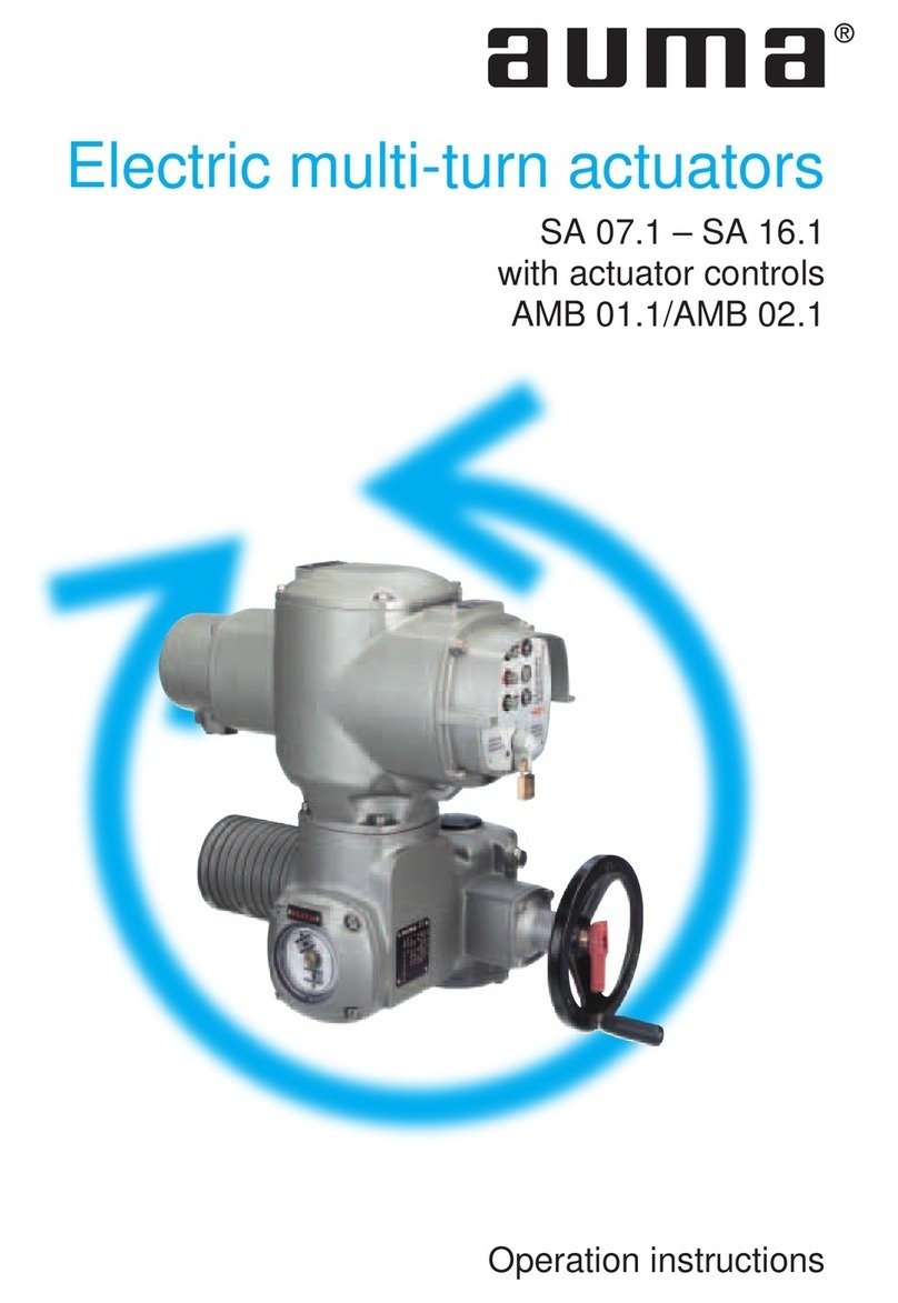
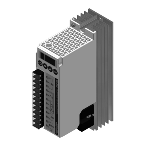
AUMA AM 01.1 Manual

Certificate Registration No.
12 100/104 4269
Actuator controls
Short instructions bus connection
AUMA MATIC
AM 01.1/ AM 02.1
AMExB 01.1/ AMExC 01.1
Profibus DP

2
Actuator controls AUMA MATIC AM/ AMExB/ AMExC
Profibus DP Short instructions bus connection
Scope of these instructions These instructions are valid for multi-turn actuators of type ranges
SA(R) 07.1 – SA(R) 16.1 and SA(R)ExC 07.1 – SA(R)ExC 16.1 and for
part-turn actuators of type ranges
SG(R) 05.1 – SG(R) 12.1 and SGExC 05.1 – SGExC 12.1
Table of contents Page
1. Safety instructions 3
1.1 Range of application 3
1.2 Commissioning (electrical connection) 3
1.3 Maintenance 3
1.4 Warnings and notes 3
2. Short description 3
3. Electrical connection 4
3.1 Power supply (standard) 4
3.2 Bus connection (standard) 5
3.3 Fitting the cover 6
3.4 Remote position transmitter 7
3.5 AUMA MATIC on wall bracket 7
3.6 Test run 7
3.7 Mains and bus connection for Ex-version with plug/ socket connector/ terminal board (KP) 8
3.8 Mains and bus connection for Ex-version with plug-in terminal connection (KES) 10
3.9 Redundant bus connection 11
3.10 Bus cables 12
3.11 Setting the Profibus DP address 13
4. Description Profibus DP interface 14
4.1 Assignment of the customer inputs of the Profibus DP interface (option) 15
4.2 Assignment Profibus DP connection 16
4.3 Assignment positioner connections 16
4.4 Checking/ setting the switches on the logic board 17
5. Appendix A Literature references 18
6. Appendix B Connecting the cable shield for the AUMA MATIC AMExB/ AMExC 01.1 18
Index 19
Addresses of AUMA offices and representatives 20

1. Safety instructions
1.1 Range of application AUMA actuators are designed for the operation of industrial valves,
e.g. globe valves, gate valves, butterfly valves and ball valves.
For other applications, please consult us. The manufacturer is not liable for
any possible damage resulting from use in other than the designated appli-
cations. Such risk lies entirely with the user. Observance of these operation
instructions is considered as part of the controls’ designated use.
1.2 Commissioning
(electrical connection) During electrical operation, certain parts inevitably carry lethal voltages.
Work on the electrical system or equipment must only be carried out by a
skilled electrician himself or by specially instructed personnel under the
control and supervision of such an electrician and in accordance with the
applicable electrical engineering rules.
1.3 Maintenance The maintenance instructions must be strictly observed, otherwise a safe
operation of the multi-turn actuator/ the controls is no longer guaranteed.
1.4 Warnings and notes Non-observance of the warnings and notes may lead to serious injuries or
damage. Qualified personnel must be thoroughly familiar with all warnings
and notes in these operation instructions.
Correct transport, proper storage, mounting, and installation, as well as
careful commissioning are essential to ensure a trouble-free and safe oper-
ation.
The following references draw special attention to safety-relevant proce-
dures in these operation instructions. Each is marked by the appropriate
pictograph.
This pictograph means: Note!
“Note” marks activities or procedures which have major influence on the
correct operation. Non-observance of these notes may lead to consequen-
tial damage.
This pictograph means: Electrostatically endangered parts!
The printed circuit boards are equiped with parts which may be damaged or
destroyed by electrostatic discharges. If the boards need to be touched
during setting, measurement, or for exchange, it must be assured that
immediately before a discharge through contact with an earthed metallic
surface (e.g. the housing) has taken place.
This pictograph means: Warning!
“Warning” marks activities or procedures which, if not carried out correctly,
can affect the safety of persons or material.
2. Short description AUMA actuators have a modular design. Motor and gearing are mounted in
a common housing.
The actuators are driven by an electric motor and controlled via the elec-
tronic controls AUMA MATIC Profibus DP. The electronic controls are
included in the scope of delivery.
3
Actuator controls AUMA MATIC AM/ AMExB/ AMExC
Short instructions bus connection Profibus DP

3. Electrical connection .Work on the electrical system or equipment must only be
carried out by a skilled electrician himself or by specially
instructed personnel under the control and supervision of
such an electrician and in accordance with the applicable
electrical engineering rules.
.Installation regulations for Profibus DP must be observed
for the wiring.
(For literature references, please refer to appendix A)
Make sure to respect electromagnetic compatibility (EMC) when installing cables:
Signal and bus cables are susceptible to interference. Electric power cables,
in particular motor cables, are interference sources.
.Lay cables being susceptible to interference or sources of interference at
the highest possible distance from each other.
.The interference immunity of signal and bus cables increases if the cables
are laid close to the ground potential, e.g in corners of cable duct close to
ground surfaces.
.If possible, avoid laying long cables and make sure that they are installed
in areas being subject to low interference.
.Avoid long parallel paths with cables being either susceptible to interfer-
ence or interference sources.
3.1 Power supply (standard) For explosion-proof version (type designation: AMExB/ AMExC), please
refer to page 8 or page 10.
.Check whether type of current, supply voltage, and frequency comply with
motor data (refer to name plate at motor).
.Loosen bolts (50.01) (figure B-1) and remove connection housing.
.Loosen screws (51.01) and remove socket carrier (51.0) from plug cover
(50.0).
.Insert cable glands suitable for connecting cables.
(The enclosure protection stated on the name plate is only ensured if suit-
able cable glands are used).
.Seal cable entries which are not used with suitable plugs.
.Connect cables according to order-related wiring diagram.
The wiring diagram applicable to the actuator is attached to the handwheel
in a weather-proof bag, together with the operation instructions. In case
the wiring diagram is not available, it can be obtained from AUMA
(state commission no., refer to name plate) or downloaded directly from
the Internet (www.auma.com).
A special parking frame (figure B-2) for protection against touching the bare
contacts and against environmental influences, in case the electrical
connection has been removed, is available.
4
Actuator controls AUMA MATIC AM/ AMExB/ AMExC
Profibus DP Short instructions bus connection
Figure A-1: Connection
50.0
50.01
51.0
51.01
Figure A-2: Parking frame (accessories)
Parking frame
Technical data Motor power connections1) Protective earth Control terminals
No. of contacts max. 6 (3 are used) 1 (leading contact) 50 pins/sockets
Marking U1, V1, W1, U2, V2, W2 1 to 50
Connecting voltage max. 750 V – 250 V
Nominal current max. 25 A – 16 A
Type of customer connection Screws Screw for ring lug Screws
Cross section max. 6 mm26 mm22.5 mm2
Material: Pin/socket carrier Polyamide Polyamide Polyamide
Contacts Brass (Ms) Brass (Ms) Brass, tin plated or gold plated (option)
1)Suitable for copper wires. For aluminium wires, please contact AUMA
Table 1: Technical data AUMA plug/ socket connector for bus connection

3.2 Bus connection (standard) For explosion-proof version (type designation: AMExB/ AMExC), please
refer to page 8 or page 10.
For version with FO (fibre optics), please refer to separate operation instruc-
tions “AUMA MATIC AM 01.1/ AM 02.1 FO connection”.
.Connect bus cable. Refer to figures B-1 to B2.
The termination resistors for channel 1 and channel 2 (options) are switched
in via switches (S1) and (S2). Both switches are supplied in position ‘OFF’.
Only switch on the termination resistors (position ‘ON’) if the actuator is the
final device in the Profibus segment.
Only switch on the termination resistors (position ‘ON’) if the
actuator is the final device within the Profibus DP segment.
5
Actuator controls AUMA MATIC AM/ AMExB/ AMExC
Short instructions bus connection Profibus DP
S1 ON Bus termination channel 1 ON
OFF Bus termination channel 1 OFF
S2 ON Bus termination channel 2 ON (option)
OFF Bus termination channel 2 OFF (option)
Table 2: Switch positions of S1 and S2
Figure B-1: Connection board (standard)
S1
Bus termination
channel 1
Connection
channel 1
Screening
S2
Bus termination
channel 2
(option)
Connection cannel 2
(redundant)
Screening
X1
P/B N/A N/A
5V P/B GND
BAA
B
Figure B-2: Connection (standard)
from previous / to next
Profibus DP device
channel 1

3.3 Fitting the cover After connection:
.Insert the socket carrier (51.0) into the plug cover (50.0) and fasten it with
screws (51.01).
.Clean sealing faces at the plug cover and the housing.
.Check whether O-ring is in good condition.
.Apply a thin film of non-acidic grease (e.g. Vaseline) to the sealing faces.
.Replace plug cover (50.0) and fasten bolts (50.01) evenly crosswise.
.Fasten cable glands with the specified torque to ensure the required
enclosure protection.
6
Actuator controls AUMA MATIC AM/ AMExB/ AMExC
Profibus DP Short instructions bus connection
Figure B-3: Connection board (for overvoltage protection)
from previous / to next
Profibus DP device
channel 1
S1
Bus termination
channel 1
S2
Bus termination
channel 2
x1 x2
X1
1234
Figure B-4: Connection for overvoltage protection
Profibus
cable
AUMA
labelling at the
connection
SUB-D 9 plug pin
(for other
Profibus devices)
Colour
A N/A 8 green
B P/B 3 red
Table 3: Assignment of Profibus cable

3.4 Remote position transmitter For the connection of remote position transmitters (potentiometer, RWG)
screened cables must be used.
3.5 AUMA MATIC on wall bracket The AUMA MATIC can also be mounted separately from the actuator on a
wall bracket.
.For the connection of actuator and AUMA MATIC on wall bracket, use suit-
able flexible and screened connecting cables.
(Preconfectioned cables can be obtained from AUMA on request)
.Permissible cable distance between actuator and AUMA MATIC amounts
to a max. of 100 m.
.Versions with potentiometer in the actuator are not suitable. Instead of the
potentiometer, an RWG has to be used in the actuator.
.Connect the wires in correct phase sequence.
Check direction of rotation before switching on.
3.6 Test run Perform test run. Please refer to the operation instructions pertaining to the
actuator (multi-turn actuator SA(R) ... / part-turn actuator SG ...).
Check limit and torque switching:
Check limit and torque switching, electronic position transmitter RWG or
potentiometer (option) and re-set where appropriate.
The settings are described in the operation instructions pertaining to the
actuator (multi-turn actuator SA(R) ... part-turn actuator SG ... ).
For actuators with feedback signal (RWG, potentiometer), a reference oper-
ation has to be performed after having changed the setting.
Perform reference operation:
.Run actuator electrically (via the push buttons OPEN and CLOSE of the
local controls) once to the end position OPEN and once to the end posi-
tion CLOSED.
.If no reference operation is performed after changing the limit switching,
the feedback signal via the bus is not correct. The bus signals the missing
reference operation as warning.
7
Actuator controls AUMA MATIC AM/ AMExB/ AMExC
Short instructions bus connection Profibus DP
Figure B-5: AM on wall bracket
Connecting cable to actuator

3.7 Mains and bus connection for Ex-version with plug/ socket connector/ terminal board (KP)
When working in potentially explosive areas, observe the
European Standards EN 60079-14 “Electrical installations in
hazardous areas” and EN 60079-17 “Inspection and mainte-
nance of electrical installations in hazardous areas”.
For the Ex-plug/ socket connector (figure D-1), the electrical mains connec-
tion is made after removing the plug cover (50.0) at the EEx e terminals of
the terminal board (51.0). The flameproof compartment (type of protection
EEx d) remains hereby closed.
.Check whether type of current, supply voltage, and frequency correspond
to motor data (refer to name plate at motor).
.Loosen bolts (50.01) (figure D-1) and remove plug cover.
.Insert cable glands with “EEx e” approval and of size suit-
able for connecting cables. For the recommended cable
glands refer to appendix B, page 18.
(The enclosure protection stated on the name plate is only
ensured if suitable cable glands are used).
.Seal cable entries which are not used with suitable plugs.
.Maximum 2 wires with the same cross section may be con-
nected to one terminal.
.Remove cable sheathing in a length of 120 – 140 mm.
Strip wires: Controls max. 8 mm, motor max. 12 mm.
For stranded wires use end-sleeves according to DIN 46228.
.Connect bus cable. Refer to figure (C-4).
The termination resistor for channel 1 is connected through linking the
terminals 1 – 4 and 3 – 2 (standard). Only connect the termination resistor
if the actuator is the final device in the Profibus segment.
.Connect screen largely to the cable glands. For the recommended cable
glands refer to appendix B, page 18.
If the actuator must be taken from the valve, e.g. for service purposes, it can be
separated from the mains without having to remove the wiring (figure C-2). For
this purpose, the screws (51.02) are removed and the plug/ socket connector is
pulled off. Plug cover (50.0) and terminal board (51.0) remain together.
Flameproof enclosure! Before opening, ensure that no
explosive gas and no voltage is present.
A special parking frame (figure C-3) for protection against touching the bare
contacts and against environmental influences is available.
8
Actuator controls AUMA MATIC AM/ AMExB/ AMExC
Profibus DP Short instructions bus connection
Figure C-2: Disconnection from mains
50.0
51.0
51.02
Figure C-3: Parking frame (accessories)
Parking frame
Figure C-1: Connection
50.0
50.01
51.0

9
Actuator controls AUMA MATIC AM/ AMExB/ AMExC
Short instructions bus connection Profibus DP
Technical data Motor power connections1) Protective earth Control terminals
No. of contacts max. 3 1 (leading contact) 38 pins/sockets
Marking U1, V1, W1 1 to 24, 31 to 50
Connecting voltage max. 550 V –250 V
Nominal current max. 25 A –10 A
Type of customer connection Screws Screws Screws
Cross section max. 6 mm26 mm21.5 mm2
Material: Pin/socket carrier Araldite/Polyamide Araldite/Polyamide Araldite/Polyamide
Contacts Brass (Ms) Brass (Ms) Brass (Ms) tin-plated
1) Suitable for copper wires. For aluminium wires, please contact AUMA.
Table 4: Technical data Ex plug/ socket connector with terminal board for explosion-proof actuators
Figure C-4: Bus connection for channel 1 (standard)
Another bus device follows the actuator
Actuator is final bus device
from previous
Profibus DP device
channel 1
to next
Profibus DP device
channel 1

3.8 Mains and bus connection for Ex-version with plug-in terminal connection (KES)
When working in potentially explosive areas, observe the
European Standards EN 60079-14 “Electrical installations in
hazardous areas” and EN 60079-17 “Inspection and mainte-
nance of electrical installations in hazardous areas”.
The bus connection is realised via terminals (figure D-1) The terminal
compartment is designed for explosion protection “EEx e” (increased
safety). The controls AUMA MATIC (type of protection EEx d) remain closed.
.Loosen bolts (1) (figure D-1) and remove terminal cover.
.Insert cable glands with “EEx e” approval and of size suit-
able for connecting cables. For the recommended cable
glands refer to appendix B, page 18.
(The enclosure protection stated on the name plate is only
ensured if suitable cable glands are used).
.Seal cable entries which are not used with suitable plugs.
Cross sections for connection:
Control cables: max. 2.5 mm²,
Motor connection: max. 10 mm²,
Suitable bus cables, see page 12.
.Connect bus cable to channel 1 according to configuration of the terminals
(figure D-2).
The termination resistor for channel 1 is connected through linking the
terminals 1 – 2 and 3 – 4.
.Only connect the termination resistors if the actuator is the final device in
the Profibus segment.
10
Actuator controls AUMA MATIC AM/ AMExB/ AMExC
Profibus DP Short instructions bus connection
Figure D-1: Plug in terminal
connection
Terminal
cover
Terminals
Terminal
board
Figure D-2: Terminal configuration for Ex connection (KES)
Another bus device
follows the actuator
Previous Next
Profibus DP device Profibus DP device
Actuator is
last bus device
Previous
Profibus DP device

3.9 Redundant bus connection AUMA Profibus DP devices can be connected with a second (redundant)
Profibus cable. If the bus on channel 1 fails, e. g. through cable break, the
slave automatically switches to channel 2.
This cable redundancy may only be applied after previous
integration test using the desired process control system!
.For versions with AUMA plug/ socket connector (subclause 3.2):
Connect redundant bus cable to channel 2 in the same way as channel 1
(refer to connection diagram figure B-2).
.For Ex-version with plug/ socket connector / terminal board (KP)
(subclause 3.7):
Connect cable B to terminal 6, cable A to terminal 7.
The termination resistor for channel 2 is connected through linking the
terminals 5 – 6 and 7 – 8.
.For Ex-version with plug-in terminal connection KES)
(subclause 3.8):
Connect cable B to terminal 6, cable A to terminal 7 (figure D-2).
The termination resistor for channel 2 is connected through linking the
terminals 5 – 6 and 7 – 8.
The setting of the redundant bus connection is realised via the parameters
4 and 5 (refer to page 16).
11
Actuator controls AUMA MATIC AM/ AMExB/ AMExC
Short instructions bus connection Profibus DP

3.10 Bus cables Only cables according to standard DIN 19245 or EN 50170-2, cable type A,
may be used for Profibus DP wiring.
A maximum of up to 32 Profibus devices may be connected in one segment.
If more devices are to be connected to one Profibus network, several
segments must be connected with repeaters.
The bus cable must be laid at a distance of at least 20 cm from other cables.
It should be laid in a separate, conductive and earthed cable trunking.
It must be ensured that there are no potential differences between the indi-
vidual devices on the Profibus (perform a potential compensation).
Cable specification cable type A for Profibus DP
Characteristic impedance: 135 to 165 Ohm, at a frequency
of 3 to 20 Mhz.
Cable capacity: < 30 pF per meter
Core diameter > 0.64 mm
Core cross section: > 0.34 mm², corresponds to AWG 22
Loop resistance: < 110 Ohm per km
Screening: Copper shielding braid or shielding braid and
shielding foil
12
Actuator controls AUMA MATIC AM/ AMExB/ AMExC
Profibus DP Short instructions bus connection
Transmission rate in kBit/s ≤93.75 187.5 500 1500
Maximum segment length in m 1200 1000 400 200
Table 5
Figure E: Example: Profibus with one segment
Bus termination
switched on
Bus termination
switched on
Profibus DP board
AUMA MATIC
Profibus DP
Connection
board
2-wire cable
Controls (master)

3.11 Setting the Profibus DP address
The bus address is set on the Profibus DP interface board.
.Loosen screws and remove cover (figure F-1)
.Set the required bus address using rotary switches S2 and S3
(figure F-2). (Factory setting: slave address 2)
Switch (S2) for setting the units digit.
Switch (S3) for setting the tens digit.
Example: The address ‘65’ is set as follows:
(S2) to position 5 = (5 * 1 = 5)
(S2) to position 6 = (6 * 10 = 60)
13
Actuator controls AUMA MATIC AM/ AMExB/ AMExC
Short instructions bus connection Profibus DP
Figure F-1
Screws
Profibus DP interface
board
Figure F-2: Profibus DP interface board
Rotary switch S3
Rotary switch S2

4. Description Profibus DP interface
S1.1 When using the external analogue input X11 AI 3/4, the switch S1.1 must be
in position AI 3.
S1.2 Switch for setting the position feedback via position transmitter potentiom-
eters/ RWG (option).
S1.2 = V: If the actuator is equipped with a potentiometer without RWG, this
switch must be in position ‘V’.
S1.2 = mA: Switch may only be in this position if an RWG is installed in the
actuator.
If the actuator is equipped with an RWG (0 – 20 mA or 4 – 20 mA), this
switch must be in position ‘mA’.
S2/S3 Rotary switches for Profibus address setting.
These two switches are used to set the address of the actuator within the
Profibus DP network. Only addresses from 0 to 125 may be allocated.
S2 Rotary switch for setting the unit digit.
S3 Rotary switch for setting the tens digit.
S4 Switch for setting the end position seating in end position CLOSED.
(In end position OPEN, switching off is always via limit seating)
This switch is used to inform the Profibus DP board about the type of
seating is to be used to operate the actuator in end position CLOSED (limit
seating or torque seating). The end position seating is set in the factory
according to the details given in the order.
The setting of the end position seating in end position CLOSED
must be the same on the Profibus DP board (switch S4) and on
the logic board (switch S1-2, figure H, page 17).
S4 = LIMIT: If the switch is in position ‘LIMIT’ (left, no dot visible), the actu-
ator is in limit seating for end position CLOSED.
S4 = TORQUE: If the switch is in position ‘TORQUE’ (right, dot visible), the
actuator is in torque seating for end position CLOSED.
14
Actuator controls AUMA MATIC AM/ AMExB/ AMExC
Profibus DP Short instructions bus connection
Figure G: Profibus DP interface board
S1.1
X8 PROFIBUS X11 AI ¾ X10 AI
S1.2
Rotary switch S3
Rotary switch S2
S4
S1.1 S1.2 S2 S3
AI 3 V
(with potentiometer)
mA
(with RWG) 02
Table 6: Standard setting of Profibus DP interface board

4.1 Assignment of the customer inputs of the Profibus DP interface (option)
X7 spare This plug provides pins for 4 digital customer inputs.
These signals are freely available inputs, which the micro-controller trans-
mits into the process representation input (byte 8, bits 0 – 3). The inputs are
internally connected to 0 V via pull-down resistors. In an unconnected state,
a logical zero is transmitted. To set an input to logical one, + 24 V DC must
be applied (pins 5 or 6).
.Proposed external wiring diagrams (appendix B of the
operation instructions) for these signals must be
observed.
.The bounce time of the connected switches should not be
more than 1 ms.
X12 First analogue customer input (analogue 2).
An external 0/4 – 20mA sensor for transmitting the measured values via the
Profibus can be connected to this input.
X11 Second analogue customer input (analogue 3/4)
A 0/4 – 20mA sensor for transmitting the measured values via the Profibus
can be connected to this input.
If the switch S1.1 is on the left side in position AI 3, the pin 5 (AN 4) is
connected to GND. Input AN 3 can be used in the same way as AN 2.
If the switch is on the right side in position AI 3-AI 4, a differential measure-
ment between AN 3 and AN 4 can be performed.
.Potential-free differential measurement is not possible.
.There is always a GND connection.
.Proposed external wiring diagrams (appendix B of opera-
tion instructions) observed.
.The inputs AN2, AN3, and AN4 do not have galvanic isola-
tion via opto-isolator. The maximum load of the 24 V
through the sensors must not exceed 40 mA.
15
Actuator controls AUMA MATIC AM/ AMExB/ AMExC
Short instructions bus connection Profibus DP
Pin Description
1 R1: digital input 1
2 R2: digital input 2
3 R3: digital input 3
4 R4: digital input 4
5 + 24 V
6 + 24 V
Table 7: Digital inputs
Pin Description
1 AN 2: analogue signal 0 – 20 mA
2 GND (system ground)
Table 8: Analogue inputs at plug X12 AI 2
Pin Description
1 + 24 V
2 GND (system ground)
3 GND (system ground)
4 AN 3+: analogue signal 0 – 20 mA (plus)
5 AN 4–: analogue signal 0 – 20 mA (minus)
6 GND (system ground)
Table 9: Analogue inputs at plug X11 AI 3/4

4.2 Assignment Profibus DP connection
X8 PROFIBUS The bus signals and the galvanically isolated voltage supply for the bus
termination, as well as the bus termination resistors located on the Profibus
DP board are connected on this plug.
4.3 Assignment positioner connections
X10 AI 1 The signals required for the position transmitter potentiometer/ potentiom-
eter with RWG are connected on this plug.
16
Actuator controls AUMA MATIC AM/ AMExB/ AMExC
Profibus DP Short instructions bus connection
Pin Description
1 Channel 1: B cable bus termination
2 Channel 1: A cable bus termination
3 Channel 2: A cable Profibus (redundant channel)
4 Channel 2: A cable Profibus (redundant channel)
5 GND float (Profibus ground)
6 + 5 V float (Profibus + 5 V)
Table 10: Assignment for plug X8
Pin Description
1 + 5 V for potentiometer
2 AN 1: analogue signal from position transmitter
3 GND (system ground)
4 + 24V for RWG
Table 11: Assignment for plug X10 AI 1

4.4 Checking/ setting the switches on the logic board
The settings on the logic board are already made in the factory, according to
the order details.
The logic board is located below the Profibus DP board.
The setting of the end position seating in end position
CLOSED must be the same on the Profibus DP board (switch
S4, figure G, page 14) and on the logic board (switch S1-2).
17
Actuator controls AUMA MATIC AM/ AMExB/ AMExC
Short instructions bus connection Profibus DP
S3-2:
Switching-off in end position OPEN.
Switch position has no influence.
When controlling via Profibus DP,
switching-off is always realised by
limit seating in en position OPEN
Position1:
Switching-off by limit seating in end
position CLOSED
Position 2:
Switching-off by torque seating in end
position CLOSED
S3-2
S1-2
S2-2
DIP switch S2-2 Programming
(ON = pressed)
Direction CLOSE Direction OPEN
Self-retaining REMOTE Self-retaining REMOTE
may not be used!
Push-to-run operation REMOTE
Self-retaining LOCAL
Push-to-run operation LOCAL
Blinker transmitter (option) Blinker transmitter
must be deactivated!
Blinker transm. deact.
Torque error: torque switch tripping
(in mid-travel) contained in
collective fault signal (insignificant
for fieldbus interface)
included not included
Table 12
Figure H: Logic board

5. Appendix A Literature references
1. As an introduction into Profibus DP:
Manfred Popp: Profibus DP, Grundlagen, Tips und Tricks für Anwender.
Hüthig Verlag, ISBN 3-7785-2676-6
2. Guidelines for the electrician:
Aufbaurichtlinien Profibus DP/FMS Order No. 2.111
Available from:
Profibus Nutzerorganisation Haid-und Neu-Str. 7
D-76131 Karlsruhe
Phone +49-721 / 96 58 590
Fax +49-721 / 96 58 589
Http:/ www.profibus.com
6. Appendix B Connecting the cable shield for AUMA MATIC AMExB/ AMExC 01.1
The shield of the fieldbus cable should be largely connected with the
respective threads.
Recommended threads e.g. WAZU-EMV/EX supplied by Hugro
(refer to www.hugro-gmbh.de).
18
Actuator controls AUMA MATIC AM/ AMExB/ AMExC
Profibus DP Short instructions bus connection

19
Actuator controls AUMA MATIC AM/ AMExB/ AMExC
Short instructions bus connection Profibus DP
Index
B
Blinker transmitter 17
Bus cable 11 - 12
Bus connection 11
C
Cable capacity 12
Cable type 12
Characteristic impedance 12
Collective fault signal 17
Connection board 5
Core cross section (bus cable) 12
Core diameter (bus cable) 12
E
Electrical connection 3 - 4
End position seating 14
L
Literature 18
Loop resistance 12
M
Maintenance 3
Motor connection 10
N
Name plate 8
O
Overvoltage protection 6
P
Parking frame 8
Plug/ socket connector 8 - 9
Power supply 4
Push-to-run operation 17
R
Remote position
transmitter RWG 7
S
Safety instructions 3
Screening (bus cable) 12
Self-retaining 17
Switching off 14,17
T
Technical data 9
Termination resistors 5
Torque switching 7
W
Wall bracket 7
Warnings 3
Information also available
on the Internet: Wiring diagram, GSD-file, inspection records and further actuator informa-
tion can be downloaded directly from the Internet by entering the order no.
or COMM no. (refer to name plate.
Our website: http://www.auma.com

Certificate Registration No.
12 100/104 4269
www.auma.com
A
UMA Riester GmbH & Co. KG
P.O. Box 1362
79373 Müllheim, Germany
Tel
Fax
www.auma.com
+49 7631 - 809-0
+49 7631 - 809 1250
+49 711 - 34803 0
+49 711 - 34803 34
A
UMA Riester GmbH & Co. KG
P. O. Box 1151
D - 73747 Ostfildern
Tel
Fax
riester@wof.auma.com
www.auma.com
For detailed information on AUMA products, please refer to the Internet:
Y000.423/003/en/1.09
Europe
AUMA Riester GmbH & Co. KG
Plant Müllheim
DE-79373 Müllheim
Tel +49 7631 809 - 0
Fax +49 7631 809 - 1250
www.auma.com
Plant Ostfildern-Nellingen
DE-73747 Ostfildern
Tel +49 711 34803 - 0
Fax +49 711 34803 - 3034
Service Center Cologne
DE-50858 Köln
Tel +49 2234 2037 - 9000
Fax +49 2234 2037 - 9099
Service Center Magdeburg
DE-39167 Niederndodeleben
Tel +49 39204 759 - 0
Fax +49 39204 759 - 9429
Service Center Bavaria
DE-85386 Eching
Tel +49 81 65 9017- 0
Fax +49 81 65 9017- 2018
AUMA Armaturenantriebe GmbH
AT-2512 Tribuswinkel
Tel +43 2252 82540
Fax +43 2252 8254050
www.auma.at
AUMA (Schweiz) AG
CH-8965 Berikon
Tel +41 566 400945
Fax +41 566 400948
AUMA Servopohony spol. s.r.o.
CZ-10200 Praha 10
Tel +420 272 700056 / 704125
Fax +420 272 704125
www.auma.cz
OY AUMATOR AB
FI-02230 Espoo
Tel +358 9 5840 22
Fax +358 9 5840 2300
www.aumator.fi
AUMA France S.A.R.L.
FR-95157 Taverny Cedex
Tel +33 1 39327272
Fax +33 1 39321755
www.auma.fr
AUMA ACTUATORS Ltd.
GB- Clevedon Nort_inth Somerset BS21
6QH
Tel +44 1275 871141
Fax +44 1275 875492
www.auma.co.uk
AUMA ITALIANA S.r.l. a socio unico
IT-20023 Cerro Maggiore (MI)
Tel +39 0331 51351
Fax +39 0331 517606
www.auma.it
AUMA BENELUX B.V.
NL-2314 XT Leiden
Tel +31 71 581 40 40
Fax +31 71 581 40 49
www.auma.nl
AUMA Polska Sp. z o.o.
PL-41-310 Dabrowa Górnicza
Tel +48 32 261 56 68
Fax +48 32 261 48 23
www.auma.com.pl
OOO Priwody AUMA
RU-141400 Moscow region for mail: 124365
Moscow a/ya 11
Tel +7 495 221 64 28
Fax +7 495 221 64 38
www.auma.ru
ERICHS ARMATUR AB
SE-20039 Malmö
Tel +46 40 311550
Fax +46 40 945515
www.erichsarmatur.se
GRØNBECH & SØNNER A/S
DK-2450 København SV
Tel +45 33 26 63 00
Fax +45 33 26 63 21
www.g-s.dk
IBEROPLAN S.A.
ES-28027 Madrid
Tel +34 91 3717130
Fax +34 91 7427126
D. G. Bellos & Co. O.E.
GR-13671 Acharnai Athens
Tel +30 210 2409485
Fax +30 210 2409486
SIGURD SØRUM A. S.
NO-1300 Sandvika
Tel +47 67572600
Fax +47 67572610
INDUSTRA
PT-2710-297 Sintra
Tel +351 2 1910 95 00
Fax +351 2 1910 95 99
MEGA Endüstri Kontrol Sistemieri Tic. Ltd. Sti.
TR-06810 Ankara
Tel +90 312 217 32 88
Fax +90 312 217 33 88
www.megaendustri.com.tr
CTS Control Limited Liability Company
UA-02099 Kiyiv
Tel +38 044 566-9971, -8427
Fax +38 044 566-9384
Africa
AUMA South Africa (Pty) Ltd.
ZA-1560 Springs
Tel +27 11 3632880
Fax +27 11 8185248
A.T.E.C.
EG- Cairo
Tel +20 2 23599680 - 23590861
Fax +20 2 23586621
America
AUMA ACTUATORS INC.
US-PA 15317 Canonsburg
Tel +1 724-743-AUMA (2862)
Fax +1 724-743-4711
www.auma-usa.com
AUMA Automação do Brasil ltda.
BR-Sao Paulo
Tel +55 11 8114-6463
AUMA Chile Representative Office
CL- La Reina Santiago de Chile
Tel +56 22 77 71 51
Fax +56 22 77 84 78
LOOP S. A.
AR-C1140ABP Buenos Aires
Tel +54 11 4307 2141
Fax +54 11 4307 8612
MAN Ferrostaal de Colombia Ltda.
CO- Bogotá D.C.
Tel +57 1 401 1300
Fax +57 1 416 5489
www.manferrostaal.com
PROCONTIC Procesos y Control Automático
EC- Quito
Tel +593 2 292 0431
Fax +593 2 292 2343
Corsusa International S.A.C.
PE- Miralflores - Lima
Tel +511444-1200 / 0044 / 2321
Fax +511444-3664
www.corsusa.com
PASSCO Inc.
PR-00936-4153 San Juan
Tel +18 09 78 77 20 87 85
Fax +18 09 78 77 31 72 77
Suplibarca
VE- Maracaibo Estado, Zulia
Tel +58 261 7 555 667
Fax +58 261 7 532 259
Asia
AUMA Actuators (Tianjin) Co., Ltd.
CN-300457 Tianjin
Tel +86 22 6625 1310
Fax +86 22 6625 1320
www.auma-china.com
AUMA (INDIA) PRIVATE LIMITED
IN-560 058 Bangalore
Tel +91 80 2839 4655
Fax +91 80 2839 2809
www.auma.co.in
AUMA JAPAN Co., Ltd.
JP-210-0848 Kawasaki-ku, Kawasaki-shi
Kanagawa
Tel +81 44 329 1061
Fax +81 44 366 2472
www.auma.co.jp
AUMA ACTUATORS (Singapore) Pte Ltd.
SG-569551 Singapore
Tel +65 6 4818750
Fax +65 6 4818269
www.auma.com.sg
AUMA Actuators Middle East W.L.L.
AE- 15268 Salmabad 704
Tel +973 17877377
PERFECT CONTROLS Ltd.
HK- Tsuen Wan, Kowloon
Tel +852 2493 7726
Fax +852 2416 3763
DW Controls Co., Ltd.
KR-153-803 Seoul Korea
Tel +82 2 2113 1100
Fax +82 2 2113 1088/1089
www.actuatorbank.com
Sunny Valves and Intertrade Corp. Ltd.
TH-10120 Yannawa Bangkok
Tel +66 2 2400656
Fax +66 2 2401095
www.sunnyvalves.co.th/
Top Advance Enterprises Ltd.
TW- Jhonghe City Taipei Hsien (235)
Tel +886 2 2225 1718
Fax +886 2 8228 1975
www.auma-taiwan.com.tw
Australia
BARRON GJM Pty. Ltd.
AU-NSW 1570 Artarmon
Tel +61 294361088
Fax +61 294393413
www.barron.com.au
2009-01-01
Other manuals for AM 01.1
2
This manual suits for next models
3
Table of contents
Other AUMA Controllers manuals
AUMA
AUMA SAR 16.2 User manual
AUMA
AUMA SAREx 07.2 - SAREx 16.2 User manual
AUMA
AUMA SGM 04.1 User manual
AUMA
AUMA NORM Series User manual
AUMA
AUMA NORM SQ 05.2 Administrator Guide

AUMA
AUMA MEC 03.1 User manual
AUMA
AUMA SAEx 25.1 User manual
AUMA
AUMA GK 10.2 User manual
AUMA
AUMA SQEx 05.2 User manual
AUMA
AUMA SA 48.1 SAR 25.1 User manual

AUMA
AUMA PROFOX PF-M100X User manual
AUMA
AUMA AUMATIC AC 01.2 User manual
AUMA
AUMA ABG 10.2 User manual

AUMA
AUMA AUMATIC AC 01.2 User manual
AUMA
AUMA SA 07.1 User manual
AUMA
AUMA SGExC 05.1 User manual
AUMA
AUMA SA Series User manual
AUMA
AUMA SA 3 User manual
AUMA
AUMA SAEx 07.2 User manual
AUMA
AUMA SG 05.1-F05 User manual
