austriamicrosystems AS5046 User manual
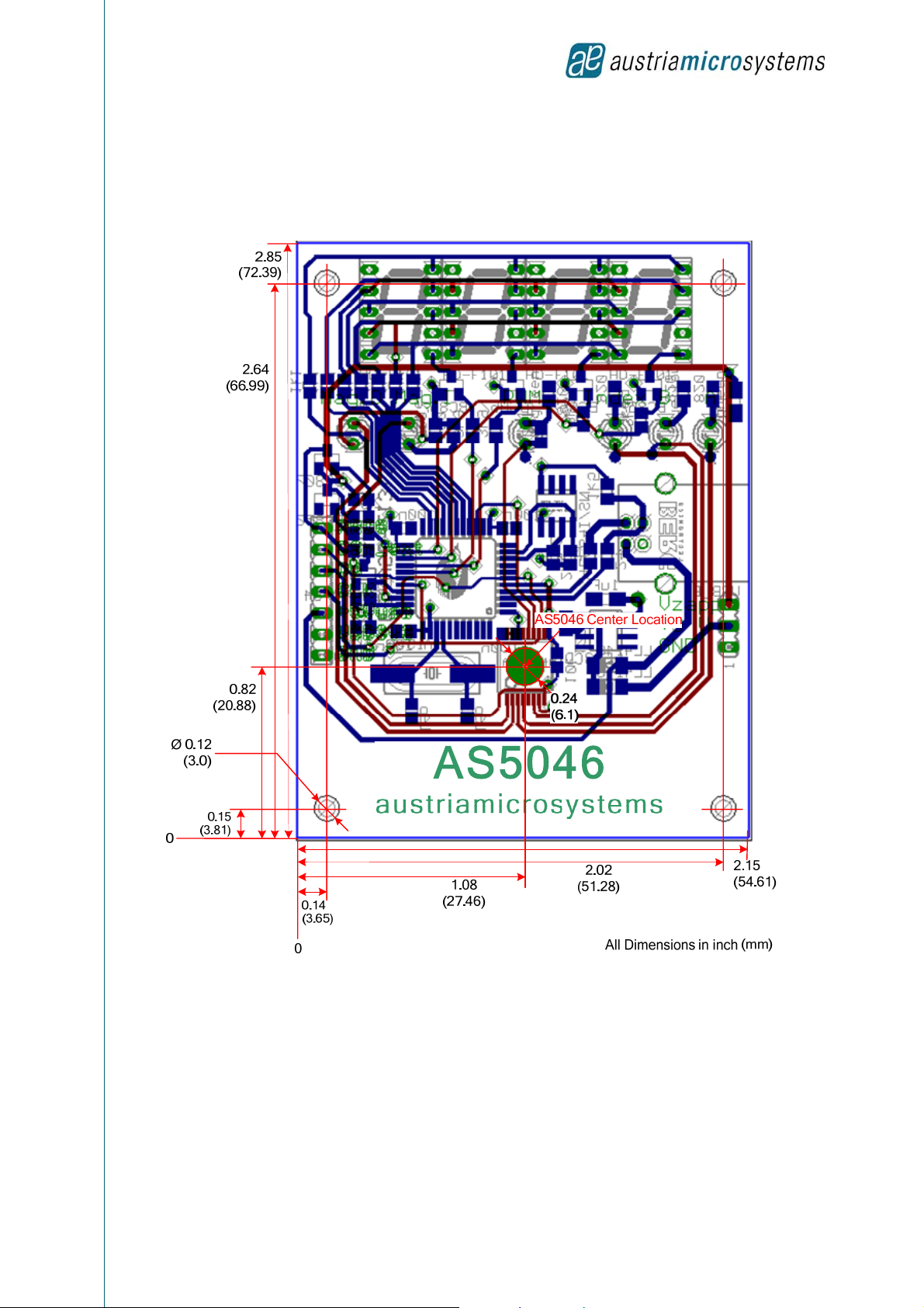
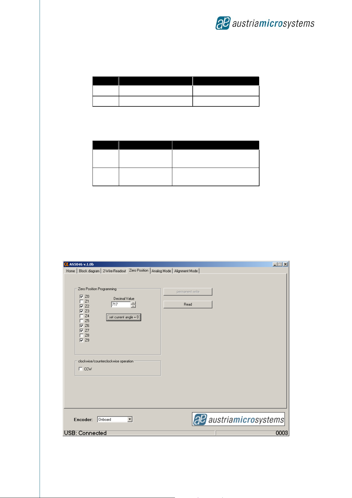
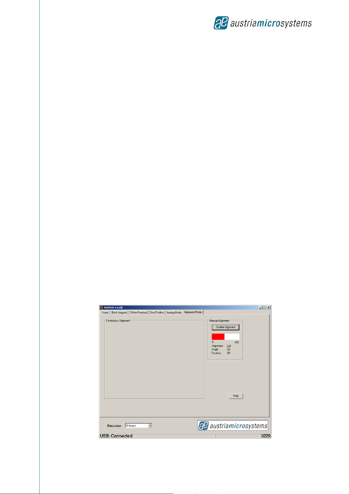
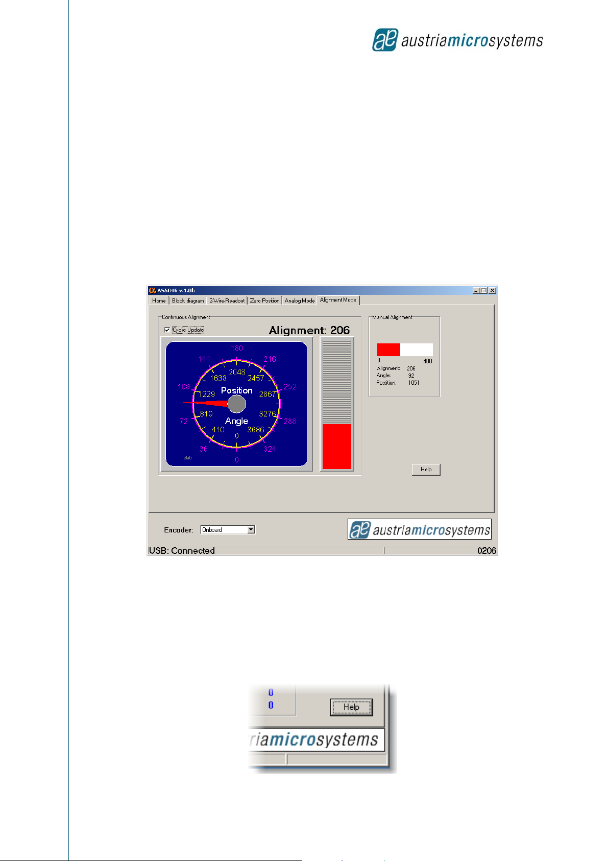
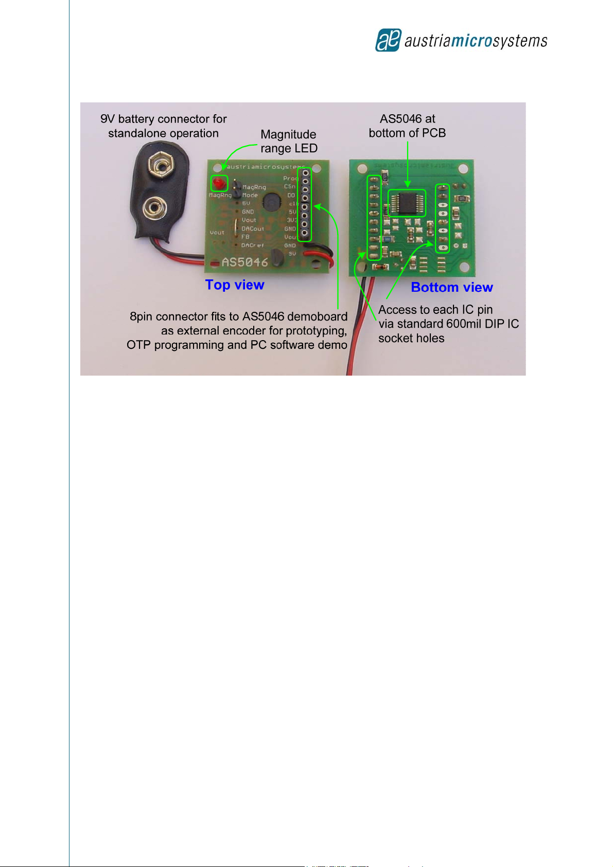
Revision 1.1, 3-Jun-08 www.austriamicrosystems.com Page 1 of 21
1General Description
The AS5046 is a contactless angular measurement system-on-chip, combining
integrated Hall elements, analog front end and digital signal processing in a
single device.
It computes the mechanical angle of a simple 2 pole diametrically magnetized
magnet that is placed either above or below the device.
The AS5046 has a resolution of 12bits, providing 4096 absolute positions.
Furthermore, an analog output proportional to the angle is available.
The AS5046 can be configured to specific customer requirements by
programming a one time programmable (OTP) register. An internal voltage
regulator allows the AS5046 to operate from either 3.3 V or 5 V supplies.
Figure 1: Typical arrangement AS5046 and magnet
1.1 The AS5046 Demoboard
The AS5046 demoboard is a complete rotary encoder system with built-in microcontroller, USB interface, 4-digit 7-segment
display and magnitude output LED. The board is USB powered or externally supplied for standalone operation. Dimensions:
72mm x 54mm (2.82 x 2.13 inch).
1.1.1 Programming
The demoboard also supports external circuits using the AS5046, such as the AS5046 adapter PCB (as shown below) or
any other AS5046 customer application. These are connected to the demoboard and can be displayed, modified or
permanently programmed using the AS5046 Demo Software.
External
supply and
programming
voltage
USB
connector
Reference
voltage,
feedback
and
analog output
AS5046
Connector for
external AS5046
Knob with
magnet
7-segment display for
standalone operation
AS5046
PROGRAMMABLE MAGNETIC ROTARY ENCODER DEMOBOARD AND SOFTWARE
OPERATION MANUAL

AS5046 12-BIT PROGRAMMABLE MAGNETIC ROTARY ENCODER
Demoboard Operation Manual
Revision 1.1, 3-Jun-08 www.austriamicrosystems.com Page 2 of 21
Figure 2: AS5046 demoboard
2Operating the AS5046 Demoboard
The AS5046 demoboard can be used in several ways:
As standalone unit supplied by a 9V-battery
Connect a 9V…12V supply to pins "GND" and "+9V" at the right side of the board. No other connections are required
As standalone unit supplied by an USB port
Connect the demoboard to a PC using a USB/USB cable (included in demoboard shipment). The board is supplied by
the 5V supply of the USB port. No other connections are required
As input device for the AS5046 demoboard software
This configuration uses the same USB hardware connection as above, but additionally the AS5046 demoboard software
is running. All indicators on the demoboard will be displayed on the PC screen as well.
Hardware Indicators
Refer to Figure 2:
2.1.1 7-Segment Display
The 4-digit display shows the absolute angle position of the magnet as a 10bit digital word (0…4095). Each digit corresponds
to (360/4096) = 0.35 degrees.
Note: The absolute position is monitored continuously. It does not require moving the magnet to a zero position before it can
calculate the absolute position. When power is lost (e.g. when you unplug the demoboard and re-connect it), it will instantly
display the correct position.
2.1.2 MagRng LED
The AS5046 provides several options of detecting movement and distance of the magnet in the vertical (Z-) direction. Signal
indicators MagINC, MagDEC and LIN are available as status bits in the serial data stream, while MagRngn is an open-drain
output that indicates an out-of range status (on in YELLOW or RED range).
2.2 Connectors
2.2.1 USB Connector
The USB connector is used to supply the demoboard with 5V power and as an interface to the AS5046 demo software, if it is
used.
2.2.2 8-pin Male Connector (left side on demoboard)
This connector is used to connect an external AS5046 encoder that can be displayed, modified and permanently
programmed with the AS5046 demoboard software (see Figure 11). It also fits the AS5046 adapter PCB (see Figure 2 and
Figure 12), which is available separately.
2.2.3 3-pin Male Connector (right side on demoboard)
This connector is used to connect an external supply (pins +9V, GND) for standalone operation, in case the USB connector
is not used. Vzapp is the connector for the programming voltage for permanently programming the external AS5046 (OTP).
2.2.4 5-pin Male Connector (right side on demoboard)
•Vout: OPAMP analog output.
•DACref: Optionally, an external reference source, applied at DACref can be used. This programming option is
useful for applications requiring a precise output voltage that is independent of supply fluctuations, for current sink
outputs or for applications with a dynamic reference, e.g. attenuation of audio signals.
•FB: Per default, the gain of the Op-Amp is internally fixed at 2x. Optionally, the internal gain setting resistors may
be switched off , allowing an external gain setting with two resistors at pins Vout ( pin #12, Op-Amp output) and FB
(pin #11, inverting input).
•Ground and VDD3V3

AS5046 12-BIT PROGRAMMABLE MAGNETIC ROTARY ENCODER
Demoboard Operation Manual
Revision 1.1, 3-Jun-08 www.austriamicrosystems.com Page 3 of 21
2.2.5 2 Mini Banana Connector (bottom right side on demoboard)
The two connectors provide easy access to the analog output pin (Vout) pin of the encoder.
2.3 Demoboard Dimensions
Figure 3: AS5046 demoboard dimensions

AS5046 12-BIT PROGRAMMABLE MAGNETIC ROTARY ENCODER
Demoboard Operation Manual
Revision 1.1, 3-Jun-08 www.austriamicrosystems.com Page 4 of 21
3AS5046 Demoboard Software
The AS5046 demoboard software can be downloaded for free from the Internet at:
http://www.austriamicrosystems.com/03products/products_detail/AS5046/download_AS5046.htm?#software
Although the AS5046 demoboard can be used as standalone unit, this software has several indicators and allows access to
extra features, such as:
Displaying the absolute angle as 10bit-word (0..4095), as absolute degrees (0..360) and as rotary dial
Displaying the analog voltage output
Displaying the status and diagnostic bits (magnitude ranges) of the AS5046
Programming the zero position (OTP)
Programming clockwise or counterclockwise operation
Putting the AS5046 in alignment mode to aid centering the magnet over the IC.
3.1 Getting Started
This software allows you to become familiar with the principle of the AS5046
magnetic rotary encoder. In order to get started, you need:
• The AS5046 demo software
• A Win2000®, Win-Me® or Win-XP® operating system
• The AS5046 demoboard and USB cable
• One free USB slot on your PC to connect the demoboard
3.2 Installing the Software
Installation Process: The installation process consists of three steps:
•Demoboard software installation
•Hardware driver installation
•Reboot
3.2.1 Step 1/3: Demoboard Software Installation
The demoboard should not be connected when the software is installed for the first time.
Run the File “AS50xx DemoSW Setup v.1.x.exe " and follow the step-by-step instructions.
Figure 4: Software installation
The software packet contains several different versions. Make sure to select the software version related to the AS5046
demo board (not to the AS5040 or AS5045) to ensure proper function (see Figure 4).

AS5046 12-BIT PROGRAMMABLE MAGNETIC ROTARY ENCODER
Demoboard Operation Manual
Revision 1.1, 3-Jun-08 www.austriamicrosystems.com Page 5 of 21
3.2.2 Hardware Driver Installation
Step 2/3: Installing the USB Controller
Connect the demoboard to a free USB slot on your PC. Your Windows® software
will automatically detect the USB controller on the demoboard:
When prompted for an installation file, refer to the file "ezusbw2k.inf" that was extracted during the demoboard software
installation (step 1) in the directory of your choice
(default C:\program files\austriamicrosystems AG\AS5046_DemoBoardSW_x.x).
After completing the installation, you should get this or a similar message (depends on platform):
Click on "finish".
3.2.3 Step 3/3: Reboot
Reboot your PC if requested by the operating system.

AS5046 12-BIT PROGRAMMABLE MAGNETIC ROTARY ENCODER
Demoboard Operation Manual
Revision 1.1, 3-Jun-08 www.austriamicrosystems.com Page 6 of 21
3.3 Software Usage
After starting the software the demo board displays several tabs described below.
Note: Before starting the software the board needs to be connected to the PC. For details read section 7.2.
3.3.1 2-Wire Readout
After starting the demo software by double-clicking the “AS5046.exe” icon and selecting the 2-Wire-Readout tab, position
information and analog output voltage of the rotary encoder is displayed along with other register information (see Figure 5).
Figure 5: SSI-readout tab
Absolute angle information:
The absolute angle information is displayed in analog and digital form. It is calculated as:
degree = (360/4096*absolute position).
Absolute position information:
This indicator displays the absolute encoder position as a 12-bit value. Each digit corresponds to
(360 degrees / 4096) = 0.0879 degrees. The range of the serial absolute output is always 0 to 4095.
Analog output voltage:
The voltage meter shows the value outputted by Vout when the feedback and DACref is at default.
Magnetic range indicators:
Three lights indicate the magnetic input field of the encoder (Red, Yellow, Green)

AS5046 12-BIT PROGRAMMABLE MAGNETIC ROTARY ENCODER
Demoboard Operation Manual
Revision 1.1, 3-Jun-08 www.austriamicrosystems.com Page 7 of 21
Green: ~45…75mT Yellow: ~ 25…45mT or ~75…135mT Red: ~<25mT or >~135mT
For details on the magnetic input field ranges please refer to the data sheet section “Z-Axis Range Indication”.
State Indicators:
Offset Comp Finish: indicates the finished offset compensation. Data is valid, when this bit = 1.
CORDIC Overflow: Internal DSP error. Data is invalid when this bit = 1.
Linearity Alarm: Internal DSP warning. The accuracy will be reduced when this bit = 1.
Magnitude Increment, Magnitude Decrement: These bits are set when the magnetic field becomes stronger
(MagInc = 1) or weaker (MagDec = 1), e.g. when the magnet is moved away or towards the chip. These signals
can be used to add a pushbutton function to the AS5046. When both bits are set, they indicate that the magnetic
field strength is out of the recommended range of 45 - 75mT (>75mT to close, <45mT to far). The AS5046 will still
continue to operate, even when both bits are set, but the accuracy may be out of spec.
Even Parity: Parity bit for transmission error detection.
Encoder: Onboard / External:
This field selects whether the onboard AS5046 (on the demo board) or an external AS5046 (connected to the 8-pin
connector at the left side of the demo board) is selected. Note that permanent write (programming) is only enabled
for the external Encoder.
USB connection status:
Displays the status of the USB connection. The connection is not polled permanently by the PC operating system,
so it may take a few seconds before the actual status is updated. If the status displays "USB: no connection", try to
unplug and re-connect the USB cable. See also section 7.2 “Suggested Sequence of Connecting and
Disconnecting”.
Figure 6: USB connection status
Sub-Window:
By double-clicking the angular gauge, a separate, resizable window appears, showing the gauge and the
incremental outputs in detail (see Figure 7).
Figure 7: SSI-tab sub-window

AS5046 12-BIT PROGRAMMABLE MAGNETIC ROTARY ENCODER
Demoboard Operation Manual
Revision 1.1, 3-Jun-08 www.austriamicrosystems.com Page 8 of 21
3.3.2 Registers
The 2-wire interface of the AS5046 enables to address, read and write four register regions described in the following.
SIU Serial Interface User: The absolute angle information is displayed in analog and digital
form. It is calculated as: degree = (360/4096*absolute position).
Automatic Gain Control: This indicator displays the absolute encoder position as a 12-bit value.
Each digit corresponds to (360 degrees / 4096) = 0.0879 degrees. The
range of the serial absolute output is always 0 to 4095.
Front End:
The voltage meter shows the value outputted by Vout when the
feedback and DACref is at default.
CORDIC Sin / Cos:
Three lights indicate the magnetic input field of the encoder (Red,
Yellow, Green)

AS5046 12-BIT PROGRAMMABLE MAGNETIC ROTARY ENCODER
Demoboard Operation Manual
Revision 1.1, 3-Jun-08 www.austriamicrosystems.com Page 9 of 21
3.3.3 Analog Mode Tab
Five bits of the OTP are used to configure the AS5046 analog output modes. (For more details please refer to the data
sheet)
Analog Output Range:
The Angular Range selector allows a digital pre-selection of the angular range. The AS5046 can be configured for
a full scale angular range of 45°, 90°, 180° or 360°.
OR1 OR0 Mode Note
0 0 360° Angular Range default mode
analog resolution= 10bit (4096 steps) over 360°
0 1 180° Angular Range analog resolution= 10bit (4096 steps) over 180°
1 0 90° Angular Range analog resolution= 10bit (4096 steps) over 90°
1 1 45° Angular Range analog resolution= 9 bit (512 steps) over 45°
Clamped Mode:
Depending on the application, the analog output can be set as rail-to-rail output or as clamped output with 10%-90% of
½ * VDD5V (pin16) or DACref (pin9).
ClampMdEN Output Note
0 0% - 100% default mode; internal DACreference
1 10% - 90% External DAC reference
Note: The output is also related to the RefExtEN OTP bit.

AS5046 12-BIT PROGRAMMABLE MAGNETIC ROTARY ENCODER
Demoboard Operation Manual
Revision 1.1, 3-Jun-08 www.austriamicrosystems.com Page 10 of 21
External Reference:
The default DAC reference is the voltage at pin #16 (VDD5V) divided by 2. Using this reference, a system that has an output
voltage ratiometric to the supply voltage can be built. Optionally, an external reference source, applied at pin#9 (DACref) can
be used.
RefExtEN Output Note
0 Voltage at pin 16 (VCC5V) default mode
1 Voltage at pin 9 (DACref)
OPAMP Feedback:
The output is ratiometric to the supply voltage (VDD5V), which can range from 3.0V to 5.5V. If the DAC reference is switched
to an external reference (pin DACref), the output is ratiometric to the external reference.
FB_intEn Feedback Note
0 external External resistors required at pin 11
and pin 12. (see Page 17)
1 internal Op-Amp gain fixed at 2
Demoboad default (programmed)
Alarm Disable:
It is possible to enable the analog output permanently (it will not be switched off even if the magnetic field is out of range). To
enable this feature an OTP bit in the factory setting (FS6) must be set. By checking “Alarm Disable” this bit is set.
3.3.4 Zero Position Tab
This tab allows you to set an individual zero position or counter-clockwise operation temporarily by modifying the according
OTP bits (Z0…Z9, CCW). When applying a programming voltage of 7.5 to 8 Volts to pin PROG (see next page) and clicking
“permanent write”, those bits can be programmed permanently (see Figure 8).
Figure 8: Zero position programming

AS5046 12-BIT PROGRAMMABLE MAGNETIC ROTARY ENCODER
Demoboard Operation Manual
Revision 1.1, 3-Jun-08 www.austriamicrosystems.com Page 11 of 21
Zero Position Programming:
Binary Indicator: This indicator will display the absolute position, which is the new Zero-position as a binary code.
This value is updated, every time the button "set current angle = 0" is clicked. The factory default setting is 0. If,
after power-up, a value other than 0 is displayed, this indicates that the encoder has already been programmed.
Decimal Indicator: This indicator will display the absolute position, which is the new Zero-position as a decimal
number. This value is updated, every time the button "set current angle = 0" is clicked. The factory default setting is
0. If, after power-up, a value other than 0 is displayed, this indicates that the encoder has already been
programmed.
Button “Read”: This button reads the settings of the OTP register. It will overwrite any settings made since the
last power-up, e.g. incremental mode, resolution, zero-position, index or ccw.
Button “Set Current Angle”: When this button is pressed, the currently read angle is updated as the new
temporary zero position. The Indicators will display the current (internal) reading and the absolute output will be
reset to = 0.
Clockwise / Counter-clockwise operation: This selector reverses the direction of both the incremental as well as
the absolute outputs. This bit should be set, when the magnet is placed underneath the AS5046 to match the
physical rotation with the indicated rotation.
Permanent programming:
The button “permanent write” is used to program the OTP registers permanently. It can only be used for the
external encoder and it is disabled by firmware when the onboard encoder is selected. To write the register
settings permanently, a programming DC voltage of 7.5V to 8V must be applied to pin Vzapp (+) of the 3-pin
connector on the right hand side of the demo board (top view). The external supply must be able to source up to
130 mA.
All the required timings for programming the external AS5046 encoder are controlled by the AS5046 demo board
USB controller. As long as no programming voltage is applied to the chip, clicking the "permanent write" button has
no effect, although a warning message is displayed.
3.3.5 Alignment Mode Tab
The Alignment Mode simplifies the centering of the magnet over the chip surface. In this mode, the absolute value
of the 10-bit angular data of the SSI interface indicates the magnitude of misalignment at a particular angle.
A low value indicates a well-centered magnet. A high value indicates that the magnet is off-center and needs to be
shifted towards the diagonal center of the encoder.
A high value indicates large X or Y displacement, but also higher absolute magnetic field strength. The magnet is
properly aligned, when the difference between highest and lowest value over one full turn is at a minimum.
Figure 9: Alignment mode

AS5046 12-BIT PROGRAMMABLE MAGNETIC ROTARY ENCODER
Demoboard Operation Manual
Revision 1.1, 3-Jun-08 www.austriamicrosystems.com Page 12 of 21
Under normal conditions, a properly aligned magnet will result in a reading of less than 32 over a full turn. The
MagINCn and MagDECn indicators will be = 1 when the alignment mode reading is < 32. At the same time, both
hardware pins MagINCn (#1) and MagDECn (#2) will be pulled to VSS. A properly aligned magnet will therefore
produce a MagINCn = MagDECn = 1 signal throughout a full 360° turn of the magnet.
Stronger magnets or short gaps between magnet and IC may show values larger than 32. These magnets are still
properly aligned as long as the difference between highest and lowest value over one full turn is at a minimum.
With AS5046 date code >=612xxx switching from alignment mode to normal operation can be done by software so
both values can be read one after another.
When clicking on the “Enable Alignment” button the alignment reading is displayed on the right hand side
(see Figure 9).
When checking “Cyclic Update” the position and angle of the encoder is displayed (see Figure 10Figure 9)
additionally to the alignment. The additional reading of the position will influence the performance of the alignment
reading.
Figure 10: Alignment with cyclic update
All functions of the AS5046 can still be used, even when the magnet is misaligned. However, the linearity error will
increase with increased misalignment.
3.4 Help Files
After installation of the software the help file AS50xx.chm can be found in the installation directory. It can be
opened by double-clicking or clicking one of the Help-Buttons of the application.

AS5046 12-BIT PROGRAMMABLE MAGNETIC ROTARY ENCODER
Demoboard Operation Manual
Revision 1.1, 3-Jun-08 www.austriamicrosystems.com Page 13 of 21
3.5 Connecting and Programming an External AS5046
You can read and program an external AS5046 encoder by connecting it to the AS5046 demoboard as shown below:
+
7
2
3
4
5
6
1
10
n
1µF
µC
only required for
OTP
p
ro
g
rammin
g
OTP: keep these wires
as short as possible
max. length = 2 inches
(5cm)
GN
D
PRO
G
CSN
SCL
5VUSB
VDD3V3
VSS
+
10µ
F
2
3
1
GN
D
VSS
VPRO
G7.5 … 8.0V
only required
for
OTP
programming
connect to
USB
interface on
PC
USB
VOUT_EX
T
8
2
3
4
5
6
7
8
9
10
11
12
13
14
15
16 1
MagRngn
Mode
CSn
SCL
NC
SDA
VSS
Prog
DACref
DACout
FB
Vout
NC
NC
VDD3V3
VDD5V
IC1
VDD3
V3
4k7
SDA
Figure 11: Connection diagram for an external AS5046 encoder connections
Since the onboard controller on the AS5046 demo board is supplied by 3.3V, the external AS5046 encoder must be
configured for 3.3V supply as well. This is done by connecting pin VDD3V3 of the demo board to both pins 15 (VDD3V3) and
16 (VDD5V) of the external encoder.
Signal GND is connected to pin 7 (VSS).
A 1µF capacitor close to the IC, between the 3.3V supply and VSS (GND) is recommended, when the cable between demo
board and external encoder is longer than about 1 foot (30 cm). OTP programming is only recommended with short wires
(max. 5cm / 2 inches) between demo board and external AS5046 (see 3.5.3).
* If longer cables are used, a pull-down resistor at the DO line of 22k - 56k Ohms is recommended to discharge the signal
between data transmissions and no static voltage is built up.
The other required signals are CSn, CLK and DO.
For OTP programming and OTPread operations, signal PROG is also required.
3.5.1 Reading the External AS5046
The external AS5046 encoder can be read in the same way as the internal encoder.
Switching from internal to external encoder can be done on the bottom left corner of the demoboard software screen:
Encoder = external:
Additionally, when encoder = external is selected, the buttons "Permanent write" and "Read" are enabled in the "Zero
Position" and "Incremental Mode" screens to allow OTP programming of the external encoder.
3.5.2 Changing Zero Position or User Parameter.
The programming options like zero position or other user parameter (MagCompEn, CCW, PWMDisable) can be modified at
any time during normal operation. Permanently programming these registers will set the default setting after power-up.
Programmed settings can again be modified during normal operation but will be reset to the programmed default state when
the power supply is interrupted.

AS5046 12-BIT PROGRAMMABLE MAGNETIC ROTARY ENCODER
Demoboard Operation Manual
Revision 1.1, 3-Jun-08 www.austriamicrosystems.com Page 14 of 21
3.5.3 OTP Programming of the External AS5046 Encoder:
To program (zap) the external AS5046 encoder, a programming voltage of 7.5 to 8V DC (130mA) must be applied to pins
VProg and GND of the 3-pin connector at the right hand side of the demoboard. A 10µF buffer cap is recommended for this
voltage (see Figure 11).
Programming is not recommended with long wires between demoboard and external encoder, as the inductance of the cable
may generate high voltage spikes, that can cause wrong programming or even harm the IC. The maximum wire length
between the demoboard connector and the external encoder should be 50mm (2”). Additionally, a 10nF ceramic capacitor
should be connected close to pin PROG and VSS.
For programming and OTP subsequent read operations, all signals shown in Figure 11 are required: PROG, CSn, DO, CLK,
VDD3V3 and VSS. All these wires should have equal length.
An OTP (one time programming) cycle is automatically initiated, when button "Permanent write" is pressed.
The default (non-programmed) logic state is "0", consequently the programmed logic state is "1". After programming, the chip
must be reset by unplugging and reconnecting the demoboard (follow the instructions on the screen). If the external chip is
not supplied by the demoboard but by an external voltage source, unplug and reconnect this supply as well.
The default state of unprogrammed bits is logic 0, programmed bits will be in logic 1 state.
Repeated OTP programming cycles are possible. Bits with a logic 0 state may still be programmed to logic 1 state, even if
some other bits of the chip have already been programmed. However, bits with a logic 1 state cannot be programmed back
to logic 0 state.
For repeated programming cycles, it is recommended to write a “0” into bits that are already programmed. Only those bits
that are supposed to be programmed should be set to logic 1.
Note that the chip will not be programmed, as long as no programming voltage is applied to VProg, although
the software will issue a warning message that the chip will be permanently programmed.

AS5046 12-BIT PROGRAMMABLE MAGNETIC ROTARY ENCODER
Demoboard Operation Manual
Revision 1.1, 3-Jun-08 www.austriamicrosystems.com Page 15 of 21
3.6 Connecting the AS5046 Adapter PCB to the Demoboard
Figure 12: AS5046 adapter PCB: top and bottom view
Note: further information about the AS5046 adapter PCB is available in a separate document:
"AS5046 Adapter PCB Operation Manual".
The AS5046 adapter PCB is intended as a standalone device that allows easy and quick testing of the AS5046 without the
need of having to make your own PCB.
It allows access to each IC pin via a standard 100mil pitch, 600mil Dual-In-Line connector, has LEDs on all digital outputs
and comes with an onboard 5V linear voltage regulator (78L05) and a battery clip to supply the board from a 9V battery.
The 7-pin female connector is designed to fit directly onto the AS5046 demoboard and use the adapter PCB as external
encoder (software setting: Encoder = external).
The demoboard however, runs at 3.3V supply voltage. The adapter PCB is configured for 5V supply voltage. Connecting
both boards without modifications will not harm any of the boards, but may lead to data transmission errors due to the
different digital levels, especially when an extension cable is used between demoboard and adapter PCB.
If you use the adapter PCB as external encoder for the AS5046 demoboard with an extension cable or experience data
transmission errors, it is recommended to configure the adapter PCB for 3.3V supply voltage. (see Figure 11)
Perform the following modifications:
disconnect the 5V supply between demoboard and adapter PCB: cut off pin "+5VUSB" at the bottom of the AS5046
demoboard
connect pins "3V3" and "5V" (see component print) on the adapter PCB. Ideally, connect the pins right at the bottom of
the 7-pin female connector with a piece of wire or solder joint.
you may also remove the 78L05 voltage regulator from the adapter PCB to prevent accidental damage of the IC when
an input voltage is applied to the regulator (and the 5V output is fed to the VDD3V3 supply pin)

AS5046 12-BIT PROGRAMMABLE MAGNETIC ROTARY ENCODER
Demoboard Operation Manual
Revision 1.1, 3-Jun-08 www.austriamicrosystems.com Page 16 of 21
4Pin Description
Pin Symbol Type Description
1 MagRngn DO_OD
Magnet Field Magnitude RaNGe
warning; active low, indicates that
the magnetic field strength is outside
of the recommended limits.
2 Mode DI_PD,
ST
Mode input. Select between low
noise (open, low) and high speed
(high) mode. Internal pull-down
resistor
3 CSn DI_PU,
ST
Chip Select, active low; Schmitt-
Trigger input, internal pull-up resistor
(~50kΩ). Must be connected to VSS
for I²C data transmission.
4 SCL DI,ST
Serial Clock Line. Clock input for I²C
data transmission
5 NC - Must be left unconnected
6 SDA DIO Serial Data Line. Bi-directional I/O
for I²C data transmission
7 VSS S Negative Supply Voltage (GND)
8 Prog DI_PD
OTP Programming Input. Internal
pull-down resistor (~74kΩ). Should
be connected to VSS if programming
is not used
9 DACref AI DAC Reference voltage input for
external reference
10 DACout AO DAC output (unbuffered, Ri ~8kΩ)
11 FB AI Feedback, OPAMP inverting input
12 Vout AO OPAMP output
13 NC - Must be left unconnected
14 NC - Must be left unconnected
15 VDD3V3 S
3V-Regulator Output for internal
core, regulated from VDD5V.
Connect to VDD5V for 3V supply
voltage. Do not load externally.
16 VDD5V S Positive Supply Voltage, 3.0 to 5.5 V
Figure 13: AS5046 pin-out and alignment tolerances
DO_OD digital output open drain
S supply pin
DO digital output
DI digital input
DI_PD digital input pull-down
DO_T digital output /tri-state
DI_PU digital input pull-up
ST Schmitt-Trigger input
MagRngn
Prog
VSS
SDA
NC
SCL
CSn
VDD5V
DACref
DACout
FB
Vout
NC
NC
1
4
3
2
13
12
11
10
9
8
7
6
5
16
15
14
Mode VDD3V3
Figure 14: AS5046 pin assignment
1
Defined
center
2.433 mm
2.433 mm
3.9 mm 3.9 mm
A
rea of allowed magnet
misalignment: 0.5mm diameter
Circle of Hall elements
on chip: 2.2mm diameter
Figure 15: Magnet alignment tolerances
4.1 Pin-Out and Magnet Misalignment
Shown above is the pin assignment and description for the AS5046. The Hall Sensors are arranged as a concentric circle at
the center of the IC with a diameter of 2.2mm (87mil). The recommended magnetic field strength at this concentric circle is
45…75mT (see datasheet).
Ideally, the center of the magnet should be located right above the center of the IC (see graph). The more the magnet is off-
center, the higher will be the non-linearity (deviation of actual position to indicated position). Consequently, the accuracy of
the system depends on the misalignment of the magnet. For best performance, the magnet should be centered within a
circle of 0.5mm diameter at the center of the chip.

AS5046 12-BIT PROGRAMMABLE MAGNETIC ROTARY ENCODER
Demoboard Operation Manual
Revision 1.1, 3-Jun-08 www.austriamicrosystems.com Page 17 of 21
5AS5046 Demoboard Schematic

AS5046 12-BIT PROGRAMMABLE MAGNETIC ROTARY ENCODER
Demoboard Operation Manual
Revision 1.1, 3-Jun-08 www.austriamicrosystems.com Page 18 of 21
6Demoboard Schematic Description
6.1 Main Parts
AS5046 rotary encoder
Microcontroller
Power supply
Indicators
Connectors
6.1.1 AS5046 Rotary Encoder
The AS5046 (IC3) is configured for 3.3V supply (pin 15 & 16 tied together). The serial interface (pins CSn, CLK, DO) is
controlled by the microcontroller. The Mode output, Magnet diagnostic outputs (MagInc, MagDec) and PWM output are
directly connected to LEDs
6.1.2 Microcontroller
The installed Cypress™ EZ-USB controller (IC1) includes an on-chip USB PC-interface. The firmware is stored in an external
E²PROM (IC2). The I/O-ports directly control the AS5046 and the 4-digit 7-segment display.
The firmware is configured such that the demoboard runs as standalone application or as an input device for the demoboard
software. No user switching is required, the software detects automatically, which mode is required.
Furthermore, the controller provides the proper pulse timings for OTP programming of an external AS5046 encoder,
connected to CON2. All that is required for programming is an external DC voltage of about 7.5V / 130mA.
6.1.3 ADC
To acquire voltage of the analog output of the onboard or external encoder an ADC (IC4) is used.
6.1.4 Power Supply
The 3.3V supply is provided by the linear voltage regulator IC5. Either the 5V supply from the USB port or an external DC
voltage at pin 2/Con3 may be used as supply inputs.
6.1.5 Indicators
The 4digit 7-segment display for the absolute angle is controlled directly by the Microcontroller. The LEDs are connected to
the digital outputs of the AS5046
6.1.6 Connectors
CON1 = USB connector for data transmission and power supply from PC
CON2 = 8-pin male 100mil pitch connector for connecting an external AS5046 application or the AS5046 adapter PCB (see
chapter 3.6)
CON3 = 3-pin male 100mil pitch connector for connecting an external power supply and the OTP programming voltage.

AS5046 12-BIT PROGRAMMABLE MAGNETIC ROTARY ENCODER
Demoboard Operation Manual
Revision 1.1, 3-Jun-08 www.austriamicrosystems.com Page 19 of 21
7Troubleshooting
7.1 Required Files
If you experience problems with the software, check that the required files are present:
Installation directory (default C:\program files\austriamicrosystems AG\AS5046_DemoBoardSW_x.x):
•AS5046.exe
•AS50xx.chm
•ezmon.sys
•ezusb.sys
•ezusbw2k.inf
In the [windows][system32][drivers] directory:
•ezmon.sys
•ezusb.sys
In the [windows][system32][drivers]/inf directory:
•ezusbw2k.inf
7.2 Suggested Sequence of Connecting and Disconnecting
When operating the demo board and software it is advisable to proceed as:
7.2.1 Running the demo software
Before starting the demo software the demo board needs to be connected to the USB port of the PC.
1. Connect to the USB port.
2. Start the software.
7.2.2 Closing the demo software
After finishing the work with the demo board the software needs to be closed before disconnecting the demo board.
1. Close the software.
2. Disconnect from the USB port.
7.3 No USB Connection when Starting the Program
If the application can not connect to the demo board it is indicated in the lower left corner as shown in Figure 16.
Figure 16: No USB connection
•In this case please check the USB connection by unplugging and re-connecting the demo board.
(Note that the software does not respond immediately after you unplugged and re-connected it. It may take a few
seconds before the USB connection is established.)
•Verify all the required files are installed properly (see above)
•Verify the correct installation of the USB controller by calling the device manager ([start] [settings] [control panel]
[system] [hardware] [device manager]) shown in Figure 17.

AS5046 12-BIT PROGRAMMABLE MAGNETIC ROTARY ENCODER
Demoboard Operation Manual
Revision 1.1, 3-Jun-08 www.austriamicrosystems.com Page 20 of 21
Figure 17: Device manager entry
7.4 USB Driver Error
If case the Device Manager displays a warning sign (see Figure 18) re-install the driver by double-clicking the device and
selecting “Update Driver” as shown in Figure 19.
Figure 18 USB Driver was not installed correctly. Figure 19 Update of the Driver in Case of Errors.
Re-install the drivers by specifying the path to the "ezusbw2k.inf" as described in section 3.2.2.
(Default direcory C:\program files\austriamicrosystems AG\AS5046_DemoBoardSW_x.x).
Note that you will only find the device listed in the Device Manager when the demo board is connected!
7.5 Hardware and software compatibility
Every AS50xx demoboard is designed to read or program all kinds of externally connected encoders (e.g. a AS5040
demoboard is capable of programming AS5035, -40, - 43, -45 and - 46 as well). Due to the variety of encoder – demoboard –
software combinations it is advisable to cross-check the setup with application note “AS5000 Hardware / Software
Compatibility”.
Table of contents
Other austriamicrosystems Media Converter manuals

austriamicrosystems
austriamicrosystems AS5163 User manual

austriamicrosystems
austriamicrosystems AS5163 User manual

austriamicrosystems
austriamicrosystems AS5215 User manual

austriamicrosystems
austriamicrosystems AS5043 User manual

austriamicrosystems
austriamicrosystems AS5130 User manual

austriamicrosystems
austriamicrosystems AS5045 User manual

austriamicrosystems
austriamicrosystems AS3990 User manual

austriamicrosystems
austriamicrosystems AS5043 User manual

austriamicrosystems
austriamicrosystems AS5040 User manual

austriamicrosystems
austriamicrosystems AS5132 User manual