PR 9116 Series User manual
PERFORMANCE
MADE
SMARTER
CCOE
Product Manual
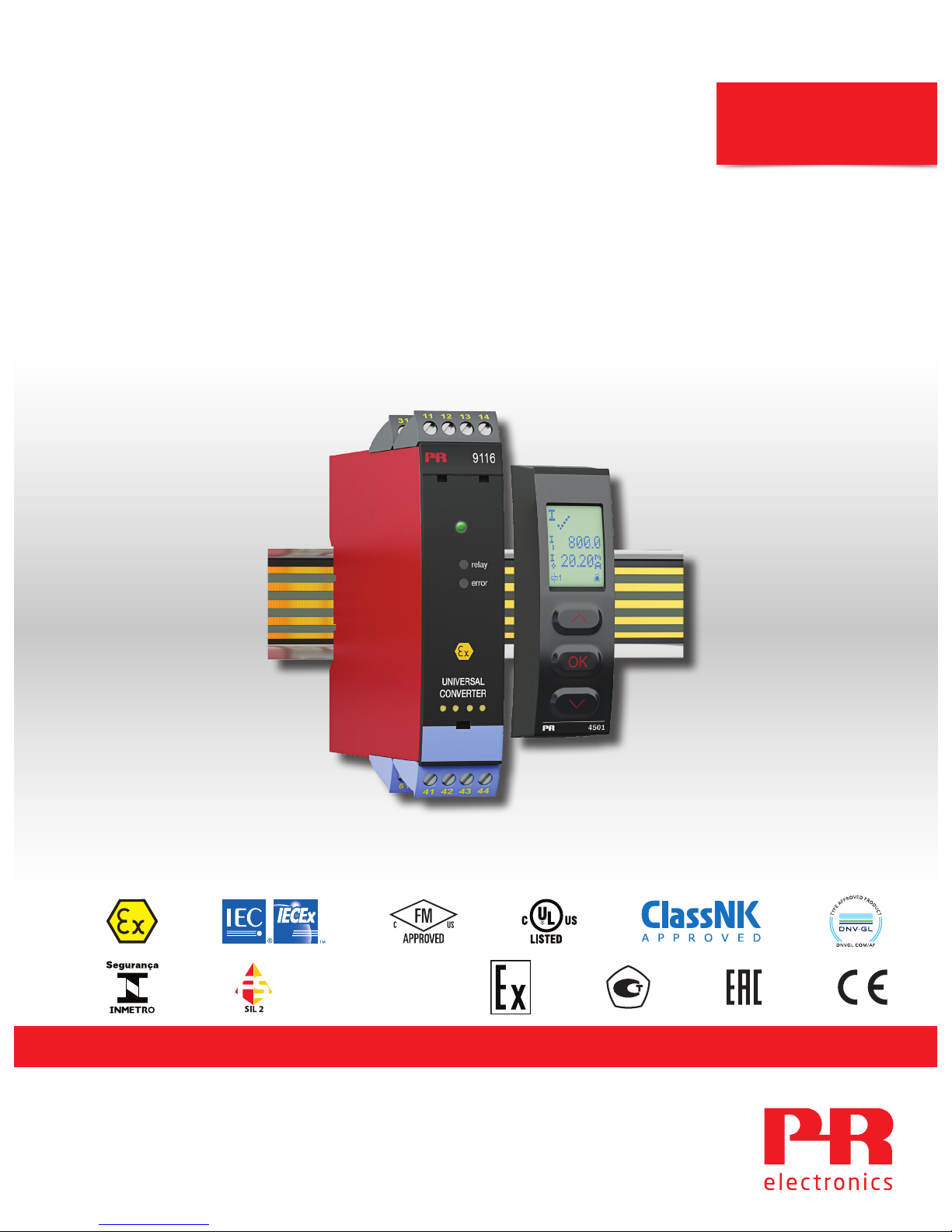
9116
Universal Converter
TEMPERATURE | I.S. INTERFACES | COMMUNICATION INTERFACES | MULTIFUNCTIONAL | ISOLATION | DISPLAY
No. 9116V107-UK
Product version: 9116-003

Communication
Display
I.S. Interface
Isolation
Multifunction
Temperature
6 Product Pillars
to meet your every need
With our innovative, patented technologies, we make signal conditioning smarter and simpler. Our portfolio is composed of six
product areas, where we offer a wide range of analog and digital devices covering over a thousand applications in industrial
and factory automation. All our products comply with or surpass the highest industry standards, ensuring reliability in even
the harshest of environments and have a 5-year warranty for greater peace of mind.
Individually outstanding, unrivalled in combination
Our range of temperature transmitters and sensors provides the highest level of signal integrity from the
measurement point to your control system. You can convert industrial process temperature signals to analog, bus or
digital communications using a highly reliable point-to-point solution with a fast response time, automatic self-
calibration, sensor error detection, low drift, and top EMC performance in any environment.
Our unique range of single devices covering multiple applications is easily deployable as your site standard. Having
one variant that applies to a broad range of applications can reduce your installation time and training, and greatly
simplify spare parts management at your facilities. Our devices are designed for long-term signal accuracy, low
power consumption, immunity to electrical noise and simple programming.
We provide inexpensive, easy-to-use, future-ready communication interfaces that can access your PR installed base
of products. All the interfaces are detachable, have a built-in display for readout of process values and diagnostics,
and can be configured via push-buttons. Product specific functionality includes communication via Modbus and
Bluetooth and remote access using our PR Process Supervisor (PPS) application, available for iOS and Android.
Our display range is characterized by its flexibility and stability. The devices meet nearly every demand for display
readout of process signals, and have universal input and power supply capabilities. They provide a real-time
measurement of your process value no matter the industry, and are engineered to provide a user-friendly and
reliable relay of information, even in demanding environments.
We deliver the safest signals by validating our products against the toughest safety standards. Through our
commitment to innovation, we have made pioneering achievements in developing I.S. interfaces with SIL 2 Full
Assessment that are both efficient and cost-effective. Our comprehensive range of analog and digital intrinsically
safe isolation barriers offers multifunctional inputs and outputs, making PR an easy-to-implement site standard.
Our backplanes further simplify large installations and provide seamless integration to standard DCS systems.
Our compact, fast, high-quality 6 mm isolators are based on microprocessor technology to provide exceptional
performance and EMC-immunity for dedicated applications at a very low total cost of ownership. They can be
stacked both vertically and horizontally with no air gap separation between units required.

9116 - Product version 9116-003 3
Universal Converter
9116B
Table of contents
Warning ................................................................................................ 4
Symbol identification .................................................................................... 4
Safety instructions ...................................................................................... 4
How to demount system 9000 ........................................................................... 5
Advanced features ...................................................................................... 6
Application ............................................................................................. 6
Technical characteristics ................................................................................. 6
Applications ............................................................................................ 7
PR 4511/4501 display / programming front ............................................................... 8
Mounting / demounting the PR 4511/4501 . . . . . . . . . . . . . . . . . . . . . . . . . . . . . . . . . . . . . . . . . . . . . . . . . . . . . . . . . . . . . . . 8
Order ................................................................................................... 9
Accessories ............................................................................................. 9
Electrical specifications .................................................................................. 9
Configuration of sensor error check ....................................................................... 14
Input signal outside range ............................................................................ 14
Sensor error detection................................................................................ 14
Error indications...................................................................................... 15
Connections ............................................................................................ 16
Block diagram ........................................................................................... 17
Signal error and cable fault indications without display front ............................................... 18
Configuration / operating the function keys ............................................................... 19
Routing diagram ........................................................................................ 22
Routing diagram, advanced settings (ADV.SET) ............................................................ 24
Help text overview ...................................................................................... 25
Graphic depiction of window ............................................................................. 27
Graphic depiction of setpoint ............................................................................. 28
Appendix . . . . . . . . . . . . . . . . . . . . . . . . . . . . . . . . . . . . . . . . . . . . . . . . . . . . . . . . . . . . . . . . . . . . . . . . . . . . . . . . . . . . . . . . . . . . . . . 29
IECEx Installation Drawing ............................................................................ 30
ATEX Installation Drawing ............................................................................ 35
FM Installation Drawing............................................................................... 40
Desenho de instalaçao INMETRO ...................................................................... 44
Document history ....................................................................................... 48

4 9116 - Product version 9116-003
Warning
The following operations should only be carried out on a disconnected device and under ESD-safe
conditions:
General mounting, wire connection and disconnection.
Troubleshooting the device.
Repair of the device and replacement of circuit breakers must be done by PR electronics A/S only.
Warning
Do not open the front plate of the device as this will cause damage to the connector for the display /
programming front PR 4511/4501.
This device contains no DIP-switches or jumpers.
Symbol identification
Triangle with an exclamation mark: Read the manual before installation and commissioning of the
device in order to avoid incidents that could lead to personal injury or mechanical damage. Warning/
demand. Potentially lethal situations.
The CE mark proves the compliance of the device with the essential requirements of the directives.
The double insulation symbol shows that the device is protected by double or reinforced insulation.
Ex devices have been approved acc. to the ATEX directive for use in connection with installations in
explosive areas. See installation drawings in appendix.
Safety instructions
Definitions
Hazardous voltages have been defined as the ranges: 75 to 1500 Volt DC, and 50 to 1000 Volt AC.
Technicians are qualified persons educated or trained to mount, operate, and also trouble-shoot technically correct and in
accordance with safety regulations.
Operators, being familiar with the contents of this manual, adjust and operate the knobs or potentiometers during normal
operation.
Receipt and unpacking
Unpack the device without damaging it and check whether the device type corresponds to the one ordered. The packing
should always follow the device until this has been permanently mounted.
Environment
Avoid direct sun light, dust, high temperatures, mechanical vibrations and shock, and rain and heavy moisture. If necessary,
heating in excess of the stated limits for ambient temperatures should be avoided by way of ventilation.
The device must be installed in pollution degree 2 or better.
The device is designed to be safe at least under an altitude up to 2 000 m.

9116 - Product version 9116-003 5
Mounting
Only technicians, who are familiar with the technical terms, warnings, and instructions in the manual and who are able to
follow these, should connect the device. Should there be any doubt as to the correct handling of the device, please contact
your local distributor or, alternatively,
PR electronics A/S
www.prelectronics.com
The use of stranded wires is not permitted for mains wiring except when wires are fitted with cable ends.
Descriptions of input / output and supply connections are shown in the block diagram and on the side label.
The device is provided with field wiring terminals and shall be supplied from a Power Supply having double / reinforced
insulation. A power switch shall be easily accessible and close to the device. The power switch shall be marked as the
disconnecting unit for the device.
For installation on Power Rail 9400 the power is supplied by Power Control Unit 9410.
Year of manufacture can be taken from the first two digits in the serial number.
Calibration and adjustment
During calibration and adjustment, the measuring and connection of external voltages must be carried out according to the
specifications of this manual. The technician must use tools and instruments that are safe to use.
Normal operation
Operators are only allowed to adjust and operate devices that are safely fixed in panels, etc., thus avoiding the danger of
personal injury and damage. This means there is no electrical shock hazard, and the device is easily accessible.
Cleaning
When disconnected, the device may be cleaned with a cloth moistened with distilled water.
Liability
To the extent the instructions in this manual are not strictly observed, the customer cannot advance a demand against PR
electronics A/S that would otherwise exist according to the concluded sales agreement.
How to demount system 9000
Picture 1:
By lifting the bottom lock, the device is detached from the DIN rail.

6 9116 - Product version 9116-003
Advanced features
• Configuration and monitoring by way of detachable display front (PR 4511/4501); process calibration, signal and relay
simulation.
• Advanced relay configuration, e.g. setpoint, window, delay, sensor error indication and power monitoring
• Copying of the configuration from one device to others of the same type via the display front.
• Reduced Uo Ex data < 8.3 V for active input signals.
• TC inputs with internal or external CJC for higher accuracy.
• Active / passive mA output via the same two terminals
Application
• The device can be mounted in the safe area and in zone 2 / cl. 1 div. 2 and receive signals from zone 0, 1, 2 and zone 20,
21, 22 including M1 / Class I/II/III, Div. 1, Gr. A-G.
• Conversion and scaling of temperature, voltage, potentiometer and linear resistance signals.
• Power supply and signal isolator for 2-wire transmitters.
• Monitoring of error events and cable breakage via the individual status relay and/or a collective electronic signal via the
power rail.
• The 9116 has been designed, developed and certified for use in SIL 2 applications according to the requirements of IEC
61508.
Technical characteristics
• 1 green and 1 red front LED indicate operation status and malfunction. 1 yellow LED indicates relay status.
• 2.6 kVAC galvanic isolation between input, output and supply.
Universal converter
9116B
• Input for RTD, TC, Ohm, potentiometer, mA and V
• Supply for 2-wire transmitters
• Active / passive mA output and relay output
• Can be supplied separately or installed on power rail, PR 9400
• SIL 2-certified via Full Assessment
54
53
52
51
44
43
42
41
44
43
42
41
12
11
14
13
31
32
33
34
*
mA
mA
+
Tx
+
-
+
+
-
+
9116 - Product version 9116-003 7
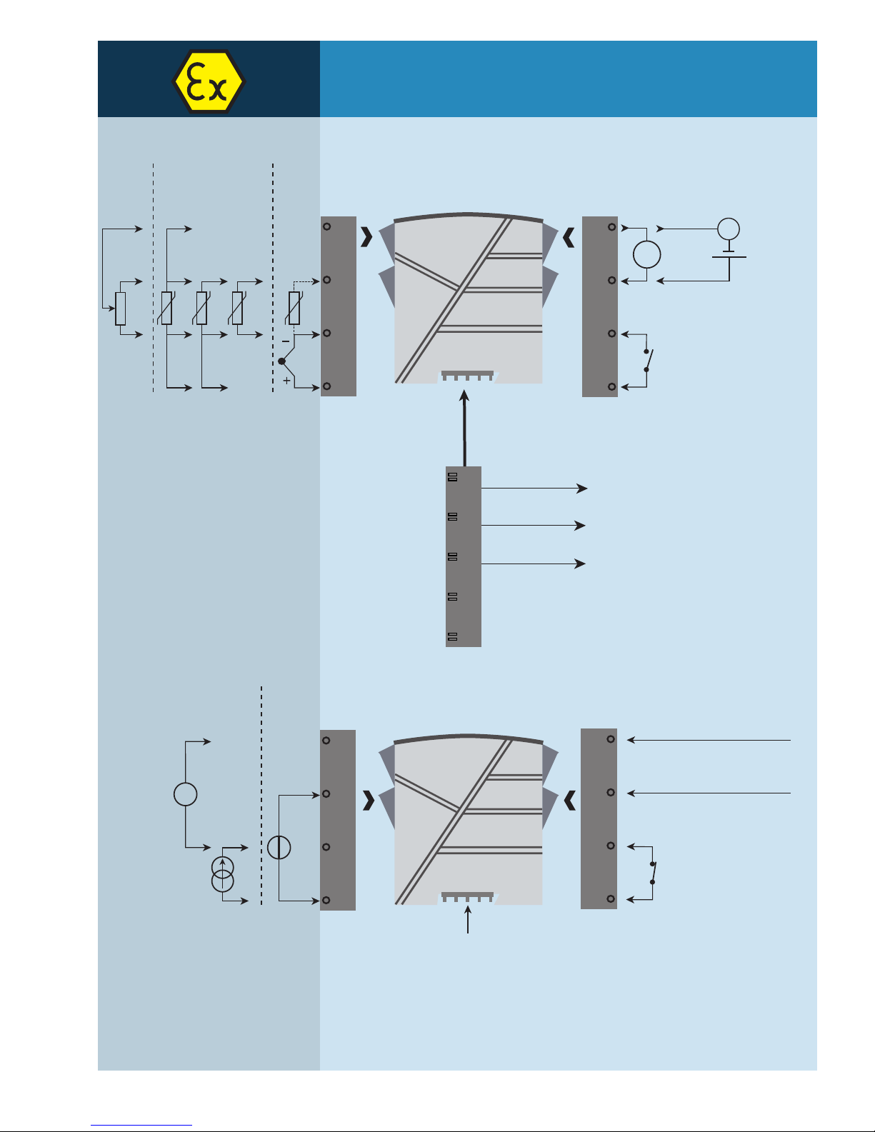
Applications
Rail, supply +
Rail, supply -
Power rail
Error signal
Zone 0, 1, 2,
20, 21, 22, M1 &
Cl. I/II/III, Div. 1
gr. A-G
Zone 2 & Cl. 1, Div. 2, gr. A-D
or Safe Area
Device status
Device status
Supply -
Supply +19.2...31.2 VDC
N.C.
No connection
No connection
Power connection:
Output signals:
Analog, 0/4...20 mA
and relay
Input signals:
Relay
Same power rail as above
Relay
RTD and lin. R
Connection,
wires TC
Poten-
tio-
meter
*Order separately:
CJC connetor 5910Ex.
VoltageCurrent
N.O.
OK
4501
1
3
4
2
3
4
8 9116 - Product version 9116-003
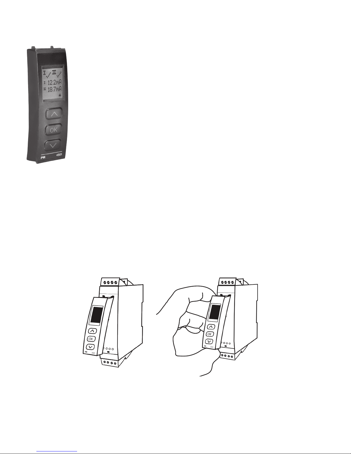
PR 4511/4501 display / programming front
Functionality
The simple and easily understandable menu structure and the explanatory help texts guide you
effortlessly and automatically through the configuration steps, thus making the product very easy to
use. Functions and configuration options are described in the section ”Configuration / operating the
function keys”.
Application
• Communications interface for modification of operational parameters in 9116.
• Can be moved from one 9116 device to another and download the configuration of the first unit to
subsequent units.
• When mounted in the process, the display shows process values and device status.
Technical characteristics
• LCD display with 4 lines:
Line 1 (H=5.57 mm) shows input status
Line 2 (H=3.33 mm) toggels between input value and tag. no.
Line 3 (H=3.33 mm) shows output value and UNIT.
Line 4 shows status for relay and communication and whether the device is SIL-locked.
Static dot = SIL-locked and flashing dot = not SIL-locked.
• Programming access can be blocked by assigning a password. The password is saved in the device
in order to ensure a high degree of protection against unauthorised modifications to the
configuration.
Mounting / demounting the PR 4511/4501
1: Insert the tabs of the PR 4511/4501 into the holes at the top of the device.
2: Hinge the PR 4511/4501 down until it snaps into place.
Demounting of the PR 4511/4501
3: Push the release button on the bottom of the PR 4511/4501 and hinge the the PR 4511/4501 out and up.
4: With the PR 4511/4501 hinged up, remove from holes at the top of the device.

9116 - Product version 9116-003 9
Accessories
4501 = Display / programming front
4511 = Communication enabler
5910Ex = CJC connector
9400 = Power rail
9404 = Module stop for rail
9410 = Power control unit
9421 = Power supply 24 V - Ex nA nC
Electrical specifications
Environmental conditions:
Operating temperature . . . . . . . . . . . . . . . . . . . . . . . . . . . . . . . . -20°C to +60°C
Storage temperature . . . . . . . . . . . . . . . . . . . . . . . . . . . . . . . . . -20°C to +85°C
Calibration temperature. . . . . . . . . . . . . . . . . . . . . . . . . . . . . . . . 20...28°C
Relative humidity . . . . . . . . . . . . . . . . . . . . . . . . . . . . . . . . . . . < 95% RH (non-cond.)
Protection degree . . . . . . . . . . . . . . . . . . . . . . . . . . . . . . . . . . . IP20
Installation in . . . . . . . . . . . . . . . . . . . . . . . . . . . . . . . . . . . . . . Pollution degree 2 & overvoltage category II.
Mechanical specifications:
Dimensions (HxWxD) . . . . . . . . . . . . . . . . . . . . . . . . . . . . . . . . . 109 x 23.5 x 104 mm
Dimensions (HxWxD) w/ 4501 / 4511 . . . . . . . . . . . . . . . . . . . . . . . 109 x 23.5 x 116 / 131 mm
Weight approx. . . . . . . . . . . . . . . . . . . . . . . . . . . . . . . . . . . . . . 185 g
Weight incl. 4501 / 4511 (approx.) . . . . . . . . . . . . . . . . . . . . . . . . . 200 g / 285 g
DIN rail type. . . . . . . . . . . . . . . . . . . . . . . . . . . . . . . . . . . . . . . DIN EN 60715 - 35 mm
Wire size . . . . . . . . . . . . . . . . . . . . . . . . . . . . . . . . . . . . . . . . . 0.13...2.08 mm2/ AWG 26...14 stranded wire
Screw terminal torque. . . . . . . . . . . . . . . . . . . . . . . . . . . . . . . . . 0.5 Nm
Vibration. . . . . . . . . . . . . . . . . . . . . . . . . . . . . . . . . . . . . . . . . IEC 60068-2-6
2...13.2 Hz . . . . . . . . . . . . . . . . . . . . . . . . . . . . . . . . . . . . . . ±1 mm
13.2...100 Hz . . . . . . . . . . . . . . . . . . . . . . . . . . . . . . . . . . . . . ±0.7 g
Common electrical specifications:
Supply voltage . . . . . . . . . . . . . . . . . . . . . . . . . . . . . . . . . . . . . 19.2...31.2 VDC
Fuse . . . . . . . . . . . . . . . . . . . . . . . . . . . . . . . . . . . . . . . . . . . 1.25 A SB / 250 VAC
Order
Example : 9116B2
Type Max. loop voltage
9116B Uo 28 VDC
Uo 21.4 VDC
: 1
: 2

10 9116 - Product version 9116-003
Max. required power is the maximum power needed at terminals 31 and 32.
Max. power dissipation is the maximum power dissipated by the device.
If the 9116 is used with the 4511 / 4501, then add 40 mW to the max. power dissipation and 70 mW to the max. required power for each
device with the 4511 / 4501.
Isolation - test / working:
Input to any. . . . . . . . . . . . . . . . . . . . . . . . . . . . . . . . . . . . . . 2.6 kVAC / 300 VAC reinforced isolation
Analog output to supply . . . . . . . . . . . . . . . . . . . . . . . . . . . . . . 2.6 kVAC / 300 VAC reinforced isolation
Output relay to analog output . . . . . . . . . . . . . . . . . . . . . . . . . . . 1.5 kVAC / 150 VAC reinforced isolation or
300 VAC basic isolation
Status relay to supply . . . . . . . . . . . . . . . . . . . . . . . . . . . . . . . . 1.5 kVAC / 150 VAC reinforced isolation
Communications interface . . . . . . . . . . . . . . . . . . . . . . . . . . . . . . Communication enabler 4511 /
Programming front 4501
Signal dynamics, input / output . . . . . . . . . . . . . . . . . . . . . . . . . . . 24 bit / 16 bit
Signal / noise ratio . . . . . . . . . . . . . . . . . . . . . . . . . . . . . . . . . . . Min. 60 dB (0...100 kHz)
Response time (0...90%, 100...10%):
Temperature input, programmable . . . . . . . . . . . . . . . . . . . . . . . . 1...60 s
mA / V input, programmable . . . . . . . . . . . . . . . . . . . . . . . . . . . . 0.4...60 s
Accuracy, the greater of the general and basic values:
Type Description Max. power
dissipation
Max. required
power
9116B1 1 channel (Ex Uo 28 V) ≤ 1.7 W ≤ 2.1 W
9116B2 1 channel (Ex Uo 21.4 V) ≤ 1.7 W ≤ 2.1 W
General values
Input type Absolute accuracy Temperature coecient
All ≤ ±0.1% of span ≤ ±0.01% of span / °C
Basic values
Input type Basic accuracy Temperature coecient
mA ≤ ±16 μA ≤ ±1.6 μA / °C
Volt ≤ ±20 μV ≤ ±2 μV / °C
Pt100, Pt200, Pt 1000 ≤ ±0.2°C ≤ ±0.02°C/°C
Pt500, Ni100,
Ni120, Ni 1000
≤ ±0.3°C
≤ ±0.03°C/°C
Pt50, Pt400, Ni50 ≤ ±0.4°C ≤ ±0.04°C/°C
Pt250, Pt300 ≤ ±0.6°C ≤ ±0.06°C/°C
Pt20 ≤ ±0.8°C ≤ ±0.08°C/°C
Pt10 ≤ ±1.4°C ≤ ±0.14°C/°C
TC type:
E, J, K, L, N, T, U
≤ ±1°C
≤ ±0.1°C/°C
TC type: R, S,
W3, W5, LR
≤ ±2°C
≤ ±0.2°C/°C
TC type: B
160...400°C
≤ ±4.5°C
≤ ±0.45°C/°C
TC type: B
400...1820°C
≤ ±2°C
≤ ±0.2°C/°C

9116 - Product version 9116-003 11
Auxiliary supplies for 9116B1:
2-wire supply (terminal 54...52) . . . . . . . . . . . . . . . . . . . . . . . . . . . 28...16.5 VDC / 0...20 mA
Auxiliary supplies for 9116B2:
2-wire supply (terminal 54...52) . . . . . . . . . . . . . . . . . . . . . . . . . . . 21.4...16.5 VDC / 0...20 mA
RTD, linear resistance and potentiometer input:
Input for RTD types:
Pt10*, Pt20*, Pt50*, Pt100, Pt200, Pt250, Pt300, Pt400, Pt500, Pt1000
Ni50, Ni100, Ni120, Ni1000
Cable resistance per wire (max.), RTD . . . . . . . . . . . . . . . . . . . . . . . 50 Ω
Sensor current; RTD . . . . . . . . . . . . . . . . . . . . . . . . . . . . . . . . . . Nom. 0.2 mA
Eect of sensor cable resistance (3- / 4-wire), RTD . . . . . . . . . . . . . . . < 0.002 Ω/ Ω
Sensor error detection, RTD . . . . . . . . . . . . . . . . . . . . . . . . . . . . . Programmable ON / OFF
Short circuit detection, RTD . . . . . . . . . . . . . . . . . . . . . . . . . . . . . Yes
* No short circuit detection for Pt10, Pt20 and Pt50
* No short circuit detection for Lin. R_0%≤ app. 18 Ω
TC input:
Cold junction compensation (CJC):
via external sensor in connector 5910. . . . . . . . . . . . . . . . . . . . . . 20...28°C ≤±1°C
-20...20°C and 28...70°C ≤±2°C
via internal CJC sensor . . . . . . . . . . . . . . . . . . . . . . . . . . . . . . . ±(2.0°C + 0.4°C * ∆t)
∆t = internal temperature - ambient temperature
Sensor error detection . . . . . . . . . . . . . . . . . . . . . . . . . . . . . . . . Programmable ON or OFF
(only wire breakage)
Sensor error current:
when detecting . . . . . . . . . . . . . . . . . . . . . . . . . . . . . . . . . . . Nom. 2 μA
else. . . . . . . . . . . . . . . . . . . . . . . . . . . . . . . . . . . . . . . . . . . 0 μA
Current input:
Measurement range . . . . . . . . . . . . . . . . . . . . . . . . . . . . . . . . . . 0...23 mA
Programmable measurement ranges . . . . . . . . . . . . . . . . . . . . . . . . 0...20 and 4...20 mA
Input resistance . . . . . . . . . . . . . . . . . . . . . . . . . . . . . . . . . . . . Nom. 20 Ω+ PTC 50 Ω
EMC - immunity influence. . . . . . . . . . . . . . . . . . . . . . . . . < ±0.5% of span
Extended EMC immunity:
NAMUR NE 21, A criterion, burst . . . . . . . . . . . . . . . . . . . . < ±1% of span
Input type Min. value Max. value Standard
Pt100
Ni100
Linear resist.
Potentiometer
-200°C
-60°C
0 Ω
10 Ω
+850°C
+250°C
10000 Ω
10000 Ω
IEC 60751
DIN 43760
-
-
Type Min. value Max. value Standard
B
E
J
K
L
N
R
S
T
U
W3
W5
LR
0°C
-100°C
-100°C
-180°C
-200°C
-180°C
-50°C
-50°C
-200°C
-200°C
0°C
0°C
-200°C
+1820°C
+1000°C
+1200°C
+1372°C
+900°C
+1300°C
+1760°C
+1760°C
+400°C
+600°C
+2300°C
+2300°C
+800°C
IEC 60584-1
IEC 60584-1
IEC 60584-1
IEC 60584-1
DIN 43710
IEC 60584-1
IEC 60584-1
IEC 60584-1
IEC 60584-1
DIN 43710
ASTM E988-90
ASTM E988-90
GOST 3044-84

0,10 A
1,00 A
0 V 50 V 100 V 150 V 200 V 250 V
CURRENT
U
RELAY
12 9116 - Product version 9116-003
Sensor error detection:
Loop break 4...20 mA . . . . . . . . . . . . . . . . . . . . . . . . . . . . . . . . Yes
NB: Only when input is selected as 4...20 mA
Voltage input:
Measurement range . . . . . . . . . . . . . . . . . . . . . . . . . . . . . . . . . . 0...12 VDC
Programmable measurement ranges . . . . . . . . . . . . . . . . . . . . . . . . 0...1 / 0.2...1 / 0...5 / 1...5 / 0...10 and 2...10 VDC
Input resistance . . . . . . . . . . . . . . . . . . . . . . . . . . . . . . . . . . . . Nom. >10 MΩ
Current output:
Signal range (span) . . . . . . . . . . . . . . . . . . . . . . . . . . . . . . . . . . 0...23 mA
Programmable signal ranges . . . . . . . . . . . . . . . . . . . . . . . . . . . . . 0...20 / 4...20 / 20...0 and 20...4 mA
Load . . . . . . . . . . . . . . . . . . . . . . . . . . . . . . . . . . . . . . . . . . . ≤600 Ω
Load stability . . . . . . . . . . . . . . . . . . . . . . . . . . . . . . . . . . . . . . ≤0.01% of span / 100 Ω
Sensor error detection . . . . . . . . . . . . . . . . . . . . . . . . . . . . . . . . 0 / 3.5 / 23 mA / none
NAMUR NE 43 Upscale / Downscale. . . . . . . . . . . . . . . . . . . . . . . . . 23 mA / 3.5 mA
Output limitation:
on 4...20 and 20...4 mA signals . . . . . . . . . . . . . . . . . . . . . . . . . . 3.8...20.5 mA
on 0...20 and 20...0 mA signals . . . . . . . . . . . . . . . . . . . . . . . . . . 0...20.5 mA
Current limit. . . . . . . . . . . . . . . . . . . . . . . . . . . . . . . . . . . . . . . ≤28 mA
Passive 2-wire output installation:
Max. external 2-wire supply . . . . . . . . . . . . . . . . . . . . . . . . . . . . . 26 VDC
Max. load resistance [Ω]. . . . . . . . . . . . . . . . . . . . . . . . . . . . . . . . (Vsupply - 3.5) / 0.023 A
Eect of external 2-wire supply voltage variation . . . . . . . . . . . . . . . . < 0.005% of span / V
Relay output in safe area:
Relay functions. . . . . . . . . . . . . . . . . . . . . . . . . . . . . . . . . . . . . Setpoint, Window, Sensor error, Power and O
Hysteresis, in % of span / display range . . . . . . . . . . . . . . . . . . . . . . 0.1...25 / 1...25
On and O delay . . . . . . . . . . . . . . . . . . . . . . . . . . . . . . . . . . . . 0...3600 s
Sensor error reaction . . . . . . . . . . . . . . . . . . . . . . . . . . . . . . . . . Break / Make / Hold
Max. voltage . . . . . . . . . . . . . . . . . . . . . . . . . . . . . . . . . . . . . . 250 VAC / VDC
Max. AC current. . . . . . . . . . . . . . . . . . . . . . . . . . . . . . . . . . . . . 2 A
Max. AC power . . . . . . . . . . . . . . . . . . . . . . . . . . . . . . . . . . . . . 500 VA
Max. DC current, resistive load:
@ Urelay ≤ 30 VDC . . . . . . . . . . . . . . . . . . . . . . . . . . . . . . . . . . 2 ADC
@ Urelay >30 VDC. . . . . . . . . . . . . . . . . . . . . . . . . . . . . . . . . . . [1380 x U-2
relay x 1.0085Urelay] ADC
Graphic depiction of [1380 x U-2
relay x 1.0085Urelay]:
Status relay in safe area:
Max. voltage . . . . . . . . . . . . . . . . . . . . . . . . . . . . . . . . . . . . . . 125 VAC / 110 VDC
Max. current. . . . . . . . . . . . . . . . . . . . . . . . . . . . . . . . . . . . . . . 0.5 AAC / 0.3 ADC
Max. AC power . . . . . . . . . . . . . . . . . . . . . . . . . . . . . . . . . . . . . 62.5 VA / 32 W
of span = of the currently selected measurement range
Urelay
50 V 150 V0 V 100 V 200 V 250 V
Current
0.10 A
0.40 A
0.80 A
0.20 A
1.00 A
0.60 A
2.00 A
3.00 A

9116 - Product version 9116-003 13
Observed authority requirements:
EMC. . . . . . . . . . . . . . . . . . . . . . . . . . . . . . . . . . . . . . . . . . . . 2014/30/EU
LVD . . . . . . . . . . . . . . . . . . . . . . . . . . . . . . . . . . . . . . . . . . . . 2014/35/EU
ATEX . . . . . . . . . . . . . . . . . . . . . . . . . . . . . . . . . . . . . . . . . . . 2014/34/EU
RoHS . . . . . . . . . . . . . . . . . . . . . . . . . . . . . . . . . . . . . . . . . . . 2011/65/EU
Approvals:
DNV-GL, Ships & Oshore . . . . . . . . . . . . . . . . . . . . . . . . . . . . . . Standard for Certification No. 2.4
ClassNK . . . . . . . . . . . . . . . . . . . . . . . . . . . . . . . . . . . . . . . . . TA18527M
c UL us, Standard for Safety . . . . . . . . . . . . . . . . . . . . . . . . . . . . . UL 61010-1
EAC . . . . . . . . . . . . . . . . . . . . . . . . . . . . . . . . . . . . . . . . . . . . TR-CU 020/2011
I.S. / Ex:
ATEX . . . . . . . . . . . . . . . . . . . . . . . . . . . . . . . . . . . . . . . . . . . KEMA 10ATEX0053 X
IECEx . . . . . . . . . . . . . . . . . . . . . . . . . . . . . . . . . . . . . . . . . . . IECEx KEM 10.0022X
c FM us. . . . . . . . . . . . . . . . . . . . . . . . . . . . . . . . . . . . . . . . . . 3038267-C
INMETRO . . . . . . . . . . . . . . . . . . . . . . . . . . . . . . . . . . . . . . . . DEKRA 16.0004 X
CCOE . . . . . . . . . . . . . . . . . . . . . . . . . . . . . . . . . . . . . . . . . . . P337349/4
EAC Ex TR-CU 012/2011 . . . . . . . . . . . . . . . . . . . . . . . . . . . . . . . RU C-DK.GB08.V.00410
Functional Safety:
SIL2 Certified & Fully Assessed acc. to IEC 61508

14 9116 - Product version 9116-003
Sensor error check:
Device: Configuration Sensor error detection:
9116 ERR.ACT=NONE - OUT.ERR=NONE. OFF
Else: ON
Outside range readout (IN.LO, IN.HI):
If the valid range of the A/D converter or the polynomal is exceeded
Input Range Readout Limit
VOLT
0...1 V / 0.2...1 V IN.LO < -25 mV
IN.HI > 1.2 V
0...10 V / 2...10 V IN.LO < -25 mV
IN.HI > 12 V
CURR 0...20 mA / 4...20 mA IN.LO < -1.05 mA
IN.HI > 25.05 mA
LIN.R
0...800 Ω IN.LO < -10 Ω
IN.HI > 900 Ω
0...10 kΩ IN.LO <-10 Ω
IN.HI > 11 kΩ
POTM 0 - 100% IN.LO < -0.5 %
IN.HI > 100.5 %
TEMP TC / RTD IN.LO < temperature range -2°C
IN.HI > temperature range +2°C
Sensor error detection (SE.BR, SE.SH):
Input Range Readout Condition
CURR Loop break (4...20 mA) SE.BR <= 3.6 mA; > = 21 mA
POTM All, SE.BR on all 3-wire SE.BR Sensor broken
SE.SH Sensor shorted
LIN.R All SE.BR Sensor broken or
wire resistance too high
For Lin. R_0%≥ app. 18 Ω SE.SH Sensor shorted
TEMP All SE.BR Sensor broken or
wire resistance too high
Pt100 to Pt1000 and Ni50 to Ni1000 SE.SH Sensor shorted
Display readout below min. / above max. (-1999, 9999):
Input Range Readout Limit
All All -1999 Display readout <-1999
9999 Display readout >9999
Configuration of sensor error check
Visualisation in the 4511/4501 of:
Input signal outside range
Sensor error detection

9116 - Product version 9116-003 15
Error indications
Readout at hardware error
Error search Readout Cause
CJC sensor error - check device temperature CJ.ER Defect internal CJC sensor or CJC temperature out
of allowed range**
CJC connector error - check CJC-connector block CJ.ER Defect (or missing) CJC-connector or temperature
out of allowed range**
Input error - check input connection and reset
power IN.ER Signal levels on input beyond limits or connected
to wrong terminals*
Output error - check output connections and
reset power AO.ER Error in analogue output current (SIL mode only)*
No communication NO.CO No communication with (4511/4501)
Flash memory error - check configuration FL.ER
CO.ER FLASH error (configuration invalid)***
Invalid configuration type or version TY.ER Configuration read from EEprom has invalid type
or rev. no.
Hardware error RA.ER RAM error*
Hardware error IF.ER Internal Flash error*
Hardware error SW.ER SW monitor error*
Hardware error AD.ER A/D converter error*
Hardware error AO.SU Analog output supply error*
Hardware error CA.ER Factory calibration error*
Hardware error CM.ER Main CPU error*
Hardware error RE.ER Relay readback error*
Hardware error II.ER Initialisation check error*
Hardware error RS.ER Reset error*
Hardware error IC.ER Input communication error*
Hardware error M1.ER Main CPU to Ch. 1 error*
Hardware error MC.ER Main CPU config. error*
Hardware error MF.ER Main CPU Flash error*
Hardware error MR.ER Main CPU RAM error*
Hardware error MS.ER Main CPU supply error*
Hardware error MP.ER Main CPU ProgFlow error*
Hardware error MI.ER Main CPU initialization check error*
Hardware error DE.ER Device error*
Hardware error FC.ER Invalid code checksum in 4511/4501
!All error indications in the display flash once per second. The help text explains the error. If the error is a
sensor error, the display backlight flashes as well - this is acknowledged (stopped) by pushing the 3button.
* Error is acknowledged by resetting the device power.
** Error can be disregarded by selecting input type different than TC.
*** Error is acknowledged by stepping through the basic setup.

16 9116 - Product version 9116-003
Connections
11 1312 14
+
-mA
11 1312 14
+
mA
31 32 3433
91 92 93 94 95
41 4342 44
+ -
41 4342 44
+ -
41 4342 44 41 4342 44
11 1312 14
N.O.
41 4342 44 41 4342 44 41 4342 44
1 3
2
51 5352 54
Tx +-
51 5352 54
+-
51 5352 54
+-
Outputs:
Inputs:
Supply and
status relay
Power rail
connections
N.C.
NC = no connection
Supply -
Supply +
Supply -
Supply +
NC
NC
Error signal
2-wire transmitter
(Passive output)
Current
(Active output) Relay
TC, internal
CJC sensorRTD, 3- / 4-wireRTD, 2-wire
*TC,
CJC connector
Potentiometer
Resistance,
3- / 4-wireResistance, 2-wire
VoltageCurrent2-wire transmitter
* Order separately:
CJC connector 5910Ex

9116
51
31
14
32
34
33
12
11
13
54
53
52
44
43
42
41
NC*NC*
CPU
FLASH
Io20 mA
I 800.0
1
Tx
*
I+
mA
mA
+
234
-
+
-
+
-
+
-
9116 - Product version 9116-003 17
Block diagram
Device status, Green
Relay status, Yellow
Ch. status, Red
Status relay N.C.
Status relay N.C.
Supply -
Supply +24 VDC
Relay N.O.
Relay N.O.
Gnd.
Power Rail connections
Input
RTD, conn.
wires
Potentiometer
TC
Volt-
age
Current
mA
output
Supply
Relay
output
* NC = no connection
Supply +
Supply -

18 9116 - Product version 9116-003
Signal error and cable fault indications without display front
List of LED and error signal indications
Condition Green LED Relay:
Yellow LED
Error:
Red LED Status relay, N.C. Power rail
signal status
No supply OFF OFF OFF De-energized Closed
Device defective OFF ON De-energized Closed
Device OK Flashing Energized Open
Signal OK Flashing OFF Energized Open
Output relay energized Flashing ON OFF Energized Open
Output relay energized
w. wire short/break Flashing ON Flashing De-energized Closed
(if activateded)
Output relay de-energized
w. wire short/break Flashing OFF Flashing De-energized Closed
(if activateded)
Output relay de-energized Flashing OFF OFF Energized Open

9116 - Product version 9116-003 19
Configuration / operating the function keys
Documentation for routing diagram.
In general
When configuring the 9116, you will be guided through all parameters and you can choose the settings which fit the
application. For each menu there is a scrolling help text which is automatically shown in line 3 on the display.
Configuration is carried out by use of the 3 function keys:
1will increase the numerical value or choose the next parameter
2will decrease the numerical value or choose the previous parameter
3will save the chosen value and proceed to the next menu
When configuration is completed, the display will return to the default state 1.0. Pressing and holding 3will return to the
previous menu or return to the default state (1.0) without saving the changed values or parameters.
If no key is activated for 1 minute, the display will return to the default state (1.0) without saving the changed values or
parameters.
Further explanations
Password protection: Programming access can be blocked by assigning a password. The password is saved in the device in
order to ensure a high degree of protection against unauthorised modifications to the configuration. Default password 2008
allows access to all configuration menus.
Password protection is mandatory in SIL applications.
Selection of units
After choosing the input signal type you can choose which process units should be shown in the display (see table). By
selection of temperature input the process value is always displayed in Celsius or Fahrenheit. This is selected in the menu
point after selection of temperature input.
CJC
In the CJC menu you can choose between CJC connector and internal cold junction compensation. The CJC connecter (PR
5910Ex) must be ordered separately.
Signal and sensor error indication via display front 4511/4501
Sensor error (see limits in the table) is displayed as SE.BR (sensor break) or SE.SH (sensor short). Signals outside the selected
range (not sensor error, see table for limits) are displayed as IN.LO indicating low input signal or IN.HI indicating high input
signal. The error indication is displayed as text in line 1 and at the same time the backlight flashes. Line 4 of the display is a
status line which shows whether the device is SIL-locked (static dot = SIL-locked and flashing dot = not SIL-locked) as well as
relay status and status for communication COM (running circle) indicating correct functioning of 4511/4501.
Signal and sensor error indication without display front
Status of the unit can also be read from the 3 LEDs in the front of the device.
Green flashing LED indicates normal operation.
No light in the green LED indicates lack of supply voltage or error in the device.
Steady red LED indicates fatal error.
Flashing red LED indicates sensor error.
Relay functions
5 different settings of relay function can be selected.
Setpoint: The unit works as a single trip amplifier
Window: The relay has a window that is defined by a low and a high setpoint. On both sides of the window the relay
has the same status.
Error function: The relay is activated by sensor error.
Power: The relay is activated as long as the power is on.
Off: The relay is deactivated.

20 9116 - Product version 9116-003
Increasing/decreasing: The relay can be set to activate at increasing or decreasing input signal.
Delay: An ON and an OFF delay can be set in the range 0...3600 s.
Hysteresis: A hysteresis can be set at 0.1...25% of the span or between 1 and 25% of display range.
Window: The window function is selected by choosing ”window” in the menu and defining a high and a low setpoint.
See the graphic depiction of the window functions on page 27.
Setpoint: The setpoint function is selected by choosing ”setpoint” in the menu and entering the desired limit. The device then
works as a single limit switch.
See the graphic depiction of the setpoint functions on page 28.
An activated relay means that the contact is closed if the contact function ”normally open” is selected, and the contact is open
if the contact function ”normally closed” is selected.
The delay time for activation and deactivation can be set independently of each other in the menus ON.DEL and OFF DEL
respectively.
Advanced functions
The unit gives access to a number of advanced functions which can be reached by answering “Yes” to the point “ADV.SET”.
Display setup: Here you can adjust the brightness contrast and the backlight. Setup of TAG numbers with 5 alphanumerics.
Input value is always shown in line 2. Selection of functional readout in line 3 of the display - choose between readout of
analog output or tag no or alternating display.
Two-point process calibration: The device can be process-calibrated in 2 points to fit a given input signal . A low input signal
(not necessarily 0%) is applied and the actual value is entered via 4511/4501. Then a high signal (not necessarily 100%) is
applied and the actual value is entered via 4511/4501. If you accept to use the calibration, the device will work according to
this new adjustment. If you later reject this menu point or choose another type of input signal the device will return to factory
calibration.
Process simulation function: In the menu point “EN.SIM” it is possible to simulate an input signal by means of the arrow keys
and thus control the output signal up or down or the relay state OFF and ON. You must exit the menu by pressing 3(no time-
out).
The simulation function exits automatically, if the 4511/4501 is detached.
Password: Here you can choose a password between 0000 and 9999 in order to protect the unit against unauthorised
modifications to the configuration. The unit is delivered default without password.
Memory: In the memory menu you can save the configuration of the device in the 4511/4501, and then move the 4511/4501
onto another device of the same type and download the configuration in the new device.
Language: In the menu ”LANG” you can choose between 7 different language versions of help texts that will appear in the
menu. You can choose between UK, DE, FR, IT, ES, SE and DK.
Power rail: In the menu ”RAIL” you can choose if sensor errors are transmitted to the central surveillance in the PR 9410
power control unit.
Safety Integrity Level (SIL): See Safety Manual for details.
Other manuals for 9116 Series
2
This manual suits for next models
4
Table of contents
Other PR Media Converter manuals


