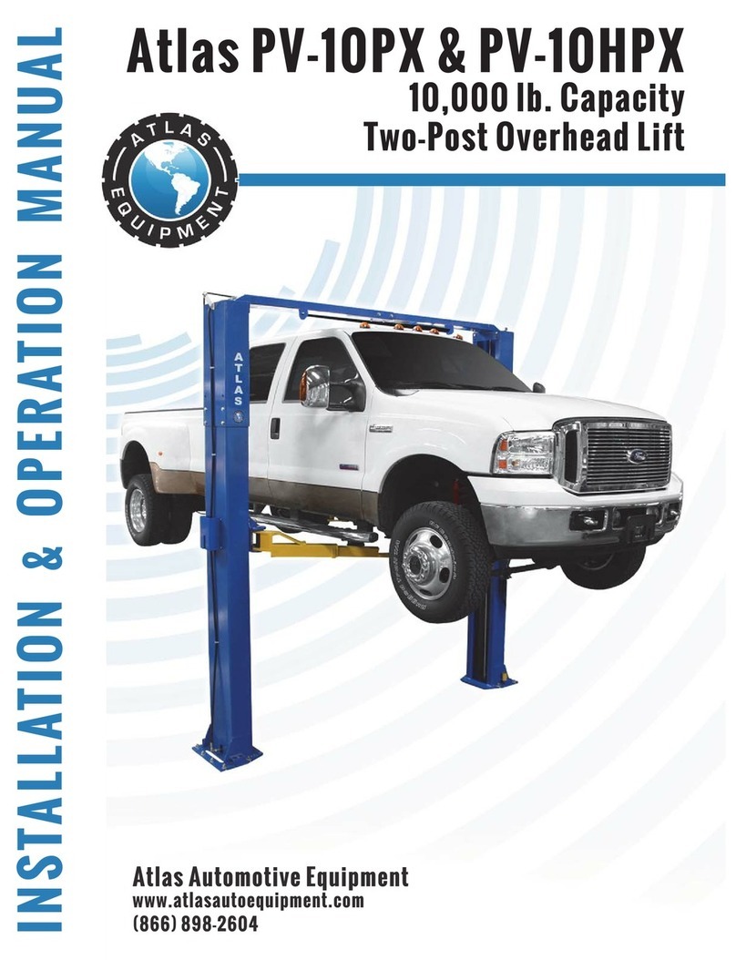
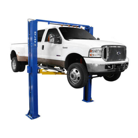
Atlas BP10000X User manual

1
Model: BP10000X
Revised: 05/26/2021

2
CONTENTS
Specification and technical..................................................................3
Installation requirement.....................................................................5
Step of Installation ...........................................................................7
Exploded view..................................................................................19
Test run……………...............................................................................27
Operation instruction........................................................................29
Maintenance....................................................................................30
Trouble shooting……………………………………………………………………………………………31
Scrapping of equipment.........................................................................31
Warranty..........................................................................................32

3
I. PRODUCT FEATURES AND SPECIFICATIONS
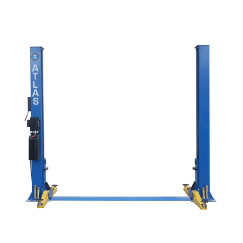
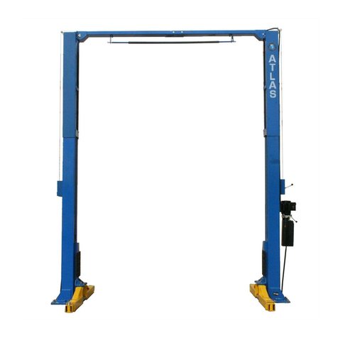
FLOORPLATE CHAIN-DRIVE TWO POST LIFT
Model BP10000X (See Fig. 1)
· Compact Floor-plate design, provides unobstructed floor space.
· Dual hydraulic cylinders, designed and made to high standards, using high quality
seals.
· Self-lubricating UHMW Polyethylene sliders and bronze bush
· Single-point safety release, and dual safety design
· 4 pieces of 3-stages arms with stackable rubber pads.
BP10000X SPECIFICATIONS
Model
Lifting
Capacity
Lifting
Time
Lifting Height
Overall
Height
Overall
Width
Minimum
Pad Height
Motor
BP10X
10,000
62S
77 3/8” - 86 3/8”
111 7/8”
139 1/8”
3 ½” – 12 ½”
3.0 HP
Fig. 1

4
Fig. 2
For Model BP10000X

5
II. INSTALLATION REQUIREMENT
A. TOOLS REQUIRED
✓Rotary Hammer Drill (Φ19)
✓Hammer
✓Level Bar
✓English Spanner (12")
✓Ratchet Spanner With Socket (28#)
Wrench set
✓Carpenter’s Chalk
✓Screw Sets
✓Tape Measure (7.5m)
✓Pliers
✓Socket Head Wrench (6#)
Lock Wrench
(10#, 13#, 14#, 15#, 17#, 19#, 24#, 27#)
Fig. 3

6
B. Equipment storage and installation requirements.
The equipment should be stored or installed in a shady, moderate temperature, ventilated
and dry place.
C. The lift package should be unloaded and transferred by forklift.
D. SPECIFICATIONS OF CONCRETE (See Fig. 5).
Concrete must adhere to the specifications listed below, failure to do so
may result in lift and/or vehicle falling.
1. Concrete must be thickness 4”minimum, without reinforcing steel bars, and
must be completely dry before lift installation.
2. Concrete must be in good condition and must be of test strength 3,000 psi
(210kg/cm²) minimum.
3. Floors must be level with no cracks or holes.
Fig. 5
E. POWER SUPPLY
220volt single phase source on a 30amp breaker with minimum of 10 gauge
wire running to the power unit. Operating voltage range is 208v-230v.
¾”
Concrete intensity must be
3000psi (210kg/cm²) minimum
Fig.4
4”

7
III.STEPS OF INSTALLATION
A. Location of Installation
Check and ensure the installation location (concrete, layout, space size etc.) is
suitable for lift installation.
B. Use a carpenter’s chalk line to establish installation layout of columns (See Fig. 6).
C. Check the parts before assembly.
1. Packaged lift and hydraulic power unit (See Fig. 7).
Fig. 7
2. Move the lift aside with forklift or hoist, and open the outer packing carefully, take off
the parts from upper and inside the column, take out the parts box, check the parts
against the shipment parts list (See Fig. 8).
Fig.8
Shipment Parts list
Floor cover
Parts box
Name plate
Fig. 6
BP10000X: 139 1/8”

8
3. Loosen the screws of the upper packing frame, take off the upper column and remove
the packing frame.
4. Lay out the parts and check against the shipment parts list.
(See Fig. 9, Fig. 10).
5. Open the parts box and check against the parts box list
(See Fig. 11).
Fig. 11
79
Fig. 10
Parts in the parts box (79)
Fig. 9

9
D. Position power-side columns
Lay columns parallel at installation site, position the power-side column according to
the actual installation site. It is suggested to install the power-side column on the
front-right side from which vehicles are driven onto the lift however the power-side
column can be on either side.
(See Fig. 12).
E. Position columns (See Fig. 13)
Stand the columns up. Check the columns for plumbness with a level and adjust
with shims if the columns are not level vertically.
Car in Direction
Power-side column
Off-side column
Assemble top-plate
using M10*35 hex
bolt with nut and lock
washer
112 1/8”
Check the columns plumbness
with level from front to back
and side to side
Fig. 12
BP10000X:139 1/8”
72/72A
Fig. 13

10
F. Fix anchor bolts
1. Prepare anchor bolts (See Fig. 14).
2. Using the prescribed rotary hammer drill and drill all the anchor holes and install the
anchor bolts. Then tighten the anchor bolts (See Fig. 15).
Note: Torque of Anchors is 150 Nm or 110 Ft Lbs.
G. Lift the carriages up by hand and lock them at the same level
(See Fig. 16).
Lock washer
Washer
Nut
4”
Fig.14
Fig.15
Fig. 16
77

11
65
66
H. Install cable (See Fig. 17)
Fig. 17
The end of cable passes
through the hole of the
carriages and is held with two
cable nuts.

12
I. Install oil hoses. (See Fig. 18).
Note: Use thread tape whenever possible.
Fig. 18
70
72
71
70
70
68
69
70
67

13
J. Install hydraulic power unit and connect oil hose (See Fig. 19).
Note: Double check the tightness of all hydraulic hoses and fittings to prevent leaks.
Fig. 19
Use 19mm wrench to Lock the
nut
75
72
Fix the oil hose with retainer.
74
72
73

14
60
55
13
60
61
78
53
53
57
56
58
59
K. Install safety device and safety cable (See Fig. 20).
NOTE: 1. Assemble safety cable from offside safety assy.
2. Pay attention to the connecting direction of safety cable.
Fig. 20
Safety cable
connecting
direction
View A
View B
4

15
Floor Cover
L: Assemble floor plate (See Fig. 21).
Fig. 21
M. Install lifting arms and adjust the arm locks
1. Install the lifting arms (See Fig. 22)
Fig. 22
Snap Ring
Use the 8#socket head
wrench to loosen the
socket bolt
Fig. 23
Spanner loose screw

16
2. Lower the carriages down to the lowest position, then use the 8# socket head wrench
to loosen the socket bolt (See Fig. 23)
3. Adjust the moon gear as arrow direction (See Fig. 24).
4. Adjust the moon gear and arm lock to make it to be meshed, then tighten bolts of
arm lock (See Fig. 25).
N. Add Hydraulic Fluid to Power Unit
To assure correct operation and to add to the longevity of all hydraulic parts use a high
quality AW32 or AW46 anti-wear hydraulic oil.
O. Install Electrical System
Connect a power source matching the requirement of the Power Unit.
Note: 1. Install the limit switch
2. For the safety of operators, the ground wire must be used.
Single phase motor (See Fig. 26).
1. Connecting the two power supply lines (active wire Land neutral wire N) to
terminals of AC contactor marked L1, L2 respectively.
2. Connecting the two motor wires to terminals of AC contactor marked T1, T2.
3. Connecting A2 to L2 of AC contactor.
4. Terminal 4# of control button is connected with terminals A1of AC contactor;
Fig. 24
Adjust moon gear
Locking the bolts after
the moon gear and
arm lock engaged well
Fig. 25

17
Terminal 3# of control button is connected with terminals L1of AC contactor.
Fig. 26
Single phase

18
IV. EXPLODED VIEW
Model BP10000X
Fig. 29
Drive In

19
Part list
No
Part no
Name
QTY
BP10000X
1
10209009
Hex bolt
6
2
10209008
Safe release cover
2
3
10209010
Clip spring
2
4
10209011
Safe release pulley
1
5
Power Side column
11203259
1
6
10206006
Washer
2
7
10206023A
Hex nut
2
8
81513001/
81513002
Power unit
1
9
11206002
Safe block pin
2
10
10209007
Torsion spring
2
11
11203263
Power side safe device
1
12
10209012
Elastic pin
8
13
11203261
Power side safe block
1
14
10209003
Hex bolt
4
15
10209004
Plastic wing
4
16
10209005
Self-lock nut
8
17
11203003
Floor cover
1
18
10201046A
Rubber pad ass
4
18A
10420138
Socket Solt
4
18B
10209134
Rubber Pads
4
18C
11680030C
Support Frame
4
19
10203156
Lifting arm ass
4
20
10209056
Self-lock nut
2
21
11206020
Pulley φ80*15
4
22
11206191
Short guard bar
4
23
10201002
Hex bolt
8
24
10209034
Spring Washer
8
25
10209033
washer
8
26
10206046
Arm Lock Bar (right)
2
27
10201010A
connector
4
28
10203005
chain
2
29
Cylinder assy.
10203078
2
30
11203176
Chain Pulley Seat Assy.
2
31
Power side carriage
11203265
1
32
10209015
slider
16
33
10209016
Carriage plastic cover
2
34
10206045
Rubber protective strip
4
35
11206046
Screw
4
36
10209153
Rack handle ring
4
37
10206046A
Arm Lock Bar (left)
2
38
10217045
Spring
4
39
10217044
Arm Lock
4
40
10206032
Snap spring
4
41
10206036
Hair Pin
4

20
No
Part no
Name
QTY
BP10000X
42
11217168
Pin for Lifting Arm
4
43
10520023
Snap Ring
4
44
10206190
Tool tray(short)
2
45
Offside carriage
11203266
1
46
11203009
Connecting plate
2
47
10209043
Hex bolt
8
48
10209046
Hex bolt
4
49
Top Plate
11203077A
2
50
11209045
Pulley
2
51
10209057A
Pulley brush bronze
6
52
Offside Column
11203260
1
53
10209049
Plastic pulley(black)
3
54
11203264
Offer-side safety release
1
55
11203784
Connecting bar
2
56
11203262
Offside safety block
1
57
10420018
Self Lock Nut
2
58
10420045
Washer
2
59
10209149
Spring Washer
2
60
10217013
Hex Bolt
2
61
10420049
Splt Pin
4
62
11209051B
Stackable Adapter(1.5")
4
63
11209052B
Stackable Adapter(2.5")
4
64
11209053B
Stackable Adapter(5")
4
65
10203069
Cable φ9.52*8290mm
2
66
10209066
Hex Nut M16
4
67
10207024
900Fitting
2
68
11201082
Straight Fitting L=98mm
2
69
10420097
900Fitting 1/4NPT(M)*1/4JIC(M)
2
70
10203107
Oil Hose L=1475mm
2
71
10211016
T Fitting
1
72
10203106
Oil Hose L=3050mm
1
73
10209060
900Fitting for power unit
1
74
10209009
Cut head bolt M6*8
6
75
11217048
Retainer
2
76
10201090
Shim (1mm)
10
10620065
Shim (2mm)
10
77
10209059
Anchor Bolt 3/4*5-1/2
12
78
10203071
Safety Cable φ2.5*7325
1
79
Parts Box
10203502A
1
Table of contents
Other Atlas Lifting System manuals

Atlas
Atlas BP8000 User manual

Atlas
Atlas Kwik Bay User manual

Atlas
Atlas FM9SL User manual

Atlas
Atlas BP12000X User manual

Atlas
Atlas pv-15p User manual

Atlas
Atlas PV-10P Owner's manual

Atlas
Atlas PV-12PX User manual
Atlas
Atlas 14KOF-EXT User manual

Atlas
Atlas PV-12PX User manual
Atlas
Atlas BP10000 User manual