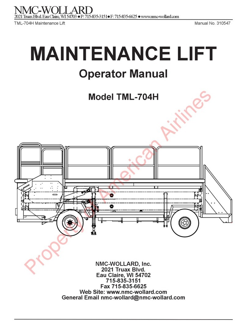
NMC-WOLLARD TML-704H User manual

NMC-WOLLARD
2021 Truax Blvd. Eau Claire, WI 54703 ● P: 715-835-3151● F: 715-835-6625 ● www.nmc-wollard.com
TML-704H Maintenance Lift Manual No. 310547
NMC-WOLLARD, Inc.
2021 Truax Blvd.
Eau Claire, WI 54702
715-835-3151
Fax 715-835-6625
Web Site: www.nmc-wollard.com
MAINTENANCE LIFT
Maintenance Manual
Model TML-704H
Property of American Airlines

CHAPTER 2 MAINTENANCE
NMC-WOLLARD
2021 Truax Blvd. Eau Claire, WI 54703 ● P: 715-835-3151● F: 715-835-6625 ● www.nmc-wollard.com
TML-704H Maintenance Lift Manual No. 310547
CHAPTER 2 MAINTENANCE
SEPTEMBER 01, 2015
PAGE TOC-1
TABLE OF CONTENTS
1. SERVICING...............................................................................................................1-1
1.1 SAFETY STOP USE .........................................................................................1-1
1.2 SAFETY PIN USE.............................................................................................1-2
1.3 PREVENTIVE MAINTENANCE AND PERIODIC INSPECTION...................1-3
1.4 BOLT TIGHTENING DATA ...............................................................................1-4
1.5 FLUIDS AND CAPACITIES AND AMBIENT TEMPERATURE RANGES .1-6
1.5.1 Fluid Req. Engine, Trans., Axle, Brake and Hyd. System..........................1-6
1.6 MAINTENANCE SCHEDULE ..........................................................................1-8
1.7 FUEL SYSTEM................................................................................................1-12
1.7.1 Special Instructions..................................................................................1-12
1.7.2 Cummins B3.3QSB, Fuel Filter, Lubricity ................................................1-13
1.8 HYDRAULIC SYSTEM ...................................................................................1-13
1.8.1 Hydraulic System Safety..........................................................................1-13
1.8.2 Special Instructions..................................................................................1-14
1.8.3 Hydraulic Reservoir - Oil Change and Cleaning......................................1-15
1.9 CLEANING SCISSORS AND PLATFORM ...................................................1-16
2. TROUBLE SHOOTING.............................................................................................2-1
2.1 SAFETY STOP USE .........................................................................................2-2
2.2 SAFETY PIN USE.............................................................................................2-3
2.3 HYDRAULIC POWER AND DISTRIBUTION SYSTEM .................................2-4
2.4 ELECTRICAL POWER AND DISTRIBUTION SYSTEM................................2-5
2.5 PLATFORM LIFT SYSTEM..............................................................................2-6
2.6 BRAKE SYSTEM ..............................................................................................2-8
2.7 ENGINE AND CONTROL SYSTEM ................................................................2-9
2.8 AUTOMATIC TRANS. AND CONTROL SYSTEM ........................................2-10
2.9 AXLES, WHEELS AND TIRES.......................................................................2-10
2.10 PROBABLE CAUSES/REMEDIES BY CODE: ELECTRICAL................... 2-11
2.11 PROBABLE CAUSES/REMEDIES BY CODE:HYDRAULIC .....................2-13
3. REMOVAL AND INSTALLATION .............................................................................3-1
3.1 GENERAL..........................................................................................................3-1
3.2 PLATFORM REMOVAL ....................................................................................3-1
3.3 SCISSORS REMOVAL.....................................................................................3-1
3.4 ENGINE AND TRANSMISSION ASSEMBLY..................................................3-2
3.4.1 Removal.....................................................................................................3-2
3.4.2 Installation..................................................................................................3-3
3.4.3 New Transmission Installation Notes.........................................................3-4
3.4.4 Instructions for Assembling the Transmission to the Engine .....................3-4
4. REPAIRS ...................................................................................................................4-1
4.1 GENERAL..........................................................................................................4-1
4.1.1 Metal Cracks..............................................................................................4-1
4.1.2 Welding.....................................................................................................4-1
4.2 AXLE BEARINGS, BRAKE ASSEMBLIES, AND DIFFERENTIAL................4-2
4.2.1 Repair of Caliper, Wheel Hub and Brake Disc..........................................4-2
Property of American Airlines

PAGE TOC-2
CHAPTER 2 MAINTENANCE
NMC-WOLLARD
2021 Truax Blvd. Eau Claire, WI 54703 ● P: 715-835-3151● F: 715-835-6625 ● www.nmc-wollard.com
TML-704H Maintenance Lift Manual No. 310547
TABLE OF CONTENTS
4.2.2 Steering Knuckle/King Pin Repair (Brierton Only) ....................................4-3
4.3 ADJUSTMENTS................................................................................................4-8
4.3.1 Electrical System .......................................................................................4-8
4.3.2 Transmission Neutral/Safety Switch ..........................................................4-8
4.3.3 Quadrastat Neutral Switch.........................................................................4-9
4.3.4 Stabilizer Retracted and Platform Down Limit Switches............................4-9
4.3.5 Hydraulic System.....................................................................................4-10
4.3.6 Main Relief Valve Pressure......................................................................4-10
4.3.7 Stabilizers Down Relief Valve Adjustment (RV2).....................................4-10
4.3.8 Stabilizer Extended Pressure Switch (PS-SE) Adjustment......................4-11
4.3.9 Lift Cylinder Flow Control Valve...............................................................4-12
4.3.10 Electric Emergency Pump Relief Valve Pressure ..................................4-13
4.3.11 Brakes....................................................................................................4-14
4.3.12 Handbrake (Parking Brake) Adjustment ................................................4-15
4.3.13 V-Belt Adjustment ..................................................................................4-15
4.3.14 Engine Speed Adjustments....................................................................4-15
4.3.15 Transmission Linkages and Cables .......................................................4-16
4.3.16 Front Wheel Alignment ..........................................................................4-16
SEPTEMBER 01, 2015
Property of American Airlines

PAGE 1-1
CHAPTER 2 MAINTENANCE
NMC-WOLLARD
2021 Truax Blvd. Eau Claire, WI 54703 ● P: 715-835-3151● F: 715-835-6625 ● www.nmc-wollard.com
TML-704H Maintenance Lift Manual No. 310547
SEPTEMBER 01, 2015
1 SERVICING
1. SERVICING
Perform lockout/tagout procedures before adjusting, lubricating cleaning
or otherwise servicing. Failure to do so could result in unexpected startup and could
cause injury or death.
1.1 SAFETY STOP USE
SAFETY STOPS MUST BE ENGAGED before working beneath
the platform or in the engine compartment or for maintenance/repair activities that
involve removing or disconnecting platform lift system hydraulic components.
1. Raise platform until frame rollers are rearward of safety stops.
2. Push operation knobs in and lower platform so frame rollers rest against safety
stops. See gure 1. If the platform were to fall, it will cause serious injury or
death.
FIGURE 1. SAFETY STOPS
Property of American Airlines

PAGE 1-2
CHAPTER 2 MAINTENANCE
NMC-WOLLARD
2021 Truax Blvd. Eau Claire, WI 54703 ● P: 715-835-3151● F: 715-835-6625 ● www.nmc-wollard.com
TML-704H Maintenance Lift Manual No. 310547
1 SERVICING
SEPTEMBER 01, 2015
1.2 SAFETY PIN USE
SAFETY PINS MUST BE USED when service requires raising
and holding the platform higher than the safety stop position.
1. Raise platform until frame rollers are rearward of safety pins.
2. Insert BOTH pins through lower roller tracks and lower frame so rollers are
against safety pins before working beneath the platform or in the engine
compartment or for maintenance/repair activities that involve removing or
disconnecting platform lift system hydraulic components. See gure 2. If the
platform were to fall, it will cause serious injury or death.
Never raise the platform with the safety pins in place and the
frame rollers are forward of the pins. Raising the platform with the pins in place will
bend the pins. Bent pins must be replaced with new pins.
FIGURE 2. SAFETY PINS
Property of American Airlines

PAGE 1-3
CHAPTER 2 MAINTENANCE
NMC-WOLLARD
2021 Truax Blvd. Eau Claire, WI 54703 ● P: 715-835-3151● F: 715-835-6625 ● www.nmc-wollard.com
TML-704H Maintenance Lift Manual No. 310547
SEPTEMBER 01, 2015
1 SERVICING
Disconnect battery before performing service to prevent accidental
startup.
Follow the recommended maintenance program to prevent unsafe
operation or accidents.
After initially mounting wheel and tire assembly, recheck lug nut torque
after the rst hour of operation and after the rst 8 hours of operation. After this, check
monthly or every 250 hours, whichever comes rst. Do not lube wheel studs as it will
result in inaccurate tightening torque. Failure to follow these procedures could result in
wheel mounting failure and loss of vehicle control.
Using non-original replacement parts is not recommended. Their use
may cause unit failure and/or aect vehicle safety.
Keep maintenance area clean and dry. Oily and wet spots are
slippery, greasy rags are a re hazard, and wet spots are dangerous around electrical
equipment.
1.3 PREVENTIVE MAINTENANCE AND PERIODIC INSPECTION
The following is a guide for conducting periodic inspections on the maintenance
lift to ensure long service life. The frequencies shown are for the unit operating in
average U.S. climate. If the unit is operated in adverse climatic conditions, such as
salt spray and extreme cold or dusty environments, adjust the inspection
schedules to a more realistic frequency.
Servicing the NMC-Wollard, Inc. Maintenance Lift truck requires little more
attention than other conventional vehicles of its type. No special tools are required,
other than those normally found in any modern garage or airline ground support
equipment servicing facility. All work should be performed in accordance with
authorized standard shop practices.
Property of American Airlines

PAGE 1-4
CHAPTER 2 MAINTENANCE
NMC-WOLLARD
2021 Truax Blvd. Eau Claire, WI 54703 ● P: 715-835-3151● F: 715-835-6625 ● www.nmc-wollard.com
TML-704H Maintenance Lift Manual No. 310547
1 SERVICING
1.4 BOLT TIGHTENING DATA
The following data is excerpted from SAE Report J1701, March, 1999. The
complete report is available from SAE at www.sae.org. It contains detailed
information about variables for torquemanagement to achieve correct fastener joint
tightening. This is an advisory guide and responsibility for its application lies with
the user. Individual application discretion is recommended.
INCH TIGHTENING TORQUE, IN-LB
Bolt Size Grade 2 Dry Grade2
Lubed
Grade 5 Dry Grade 5
Lubed
Grade 8 Dry Grade 8
Lubed
0.250-28 75 56.0 116.0 87.0 164 123
0.250-20 66.0 49.0 101.0 76.0 143 107
0.3125-24 150.0 112.0 230.0 173.0 327 245
0.3125-18 135.0 101.0 209.0 157.0 295 221
0.375-24 272 204.0 420.0 315.0 593 445
0.375-16 240 180 370 278.0 523 392
0.4375-20 428.0 321.0 662.0 496.0 935 700
0.4375-14 384 288 593.0 445.0 837 628
0.500-20 660.0 495.0 1020.0 764.0 1440 1080
0.500-13 585.0 439.0 904.0 678.0 1277 958
0.5625-18 78 59 121 91 171 128
0.5625-12 70 53 109 82 154 115
0.625-18 110 82 170 127 240 180
0.625-11 97 73 150 113 212 159
0.750-16 192 144 297 223 420 315
0.750-10 172 129 269 201 376 282
1.000-12 -- -- 704 528 995 746
1.000-8 -- -- 644 483 909 681
SEPTEMBER 01, 2015
Property of American Airlines

PAGE 1-5
CHAPTER 2 MAINTENANCE
NMC-WOLLARD
2021 Truax Blvd. Eau Claire, WI 54703 ● P: 715-835-3151● F: 715-835-6625 ● www.nmc-wollard.com
TML-704H Maintenance Lift Manual No. 310547
1 SERVICING
SEPTEMBER 01, 2015
METRIC TIGHTENING TORQUE N-m
Bolt Size Class 4.6
Dry
Class 4.6
Lubed
Class 4.8
Dry
Class 4.8
Lubed
Class 5.8
Dry
Class 5.8
Lubed
3.0 x 0.5 0.50 0.40 0.70 0.50 - -
3.5 x 0.6 0.80 0.60 1.10 0.80 - -
4.0 x 0.7 1.20 0.90 1.60 1.20 - -
5.0 x 0.8 2.40 1.80 3.30 2.50 4.00 3.00
6.0 x 1.0 4.00 3.00 5.66 4.20 6.90 5.20
8.0 x 1.25 9.90 7.40 13.60 10.20 16.70 12.50
10.0 x 1.50 19.60 14.70 27.00 20.00 33.10 24.80
12.0 x 1.75 34.10 25.60 47.00 35.00 58.00 43.00
14.0 x 2.00 54.30 40.80 75.00 56.00 92.00 69.00
Bolt Size Class 8.8
Dry
Class 8.8
Lubed
Class 9.8
Dry
Class9.8
Lubed
Class 10.9
Dry
Class 10.9
Lubed
8.0 x 1.25 26.40 19.80 28.50 21.40 36.50 27.30
10.0 x 1.50 52.20 39.20 56.60 42.40 72.20 54.20
12.0 x 1.75 91.00 68.00 99.00 74.00 126.00 94.00
14.0 x 2.00 145.00 109.00 157.00 118.00 200.00 150.00
16.0 x 2.00 226.00 170.00 245.00 184.00 313.00 235.00
20.0 x 2.50 441.00 331.00 478.00 358.00 610.00 458.00
24.0 x 3.00 762.00 572.00 826.00 620.00 1055.00 791.00
30.0 x 3.50 1515.00 1136.00 1641.00 1231.00 2095.00 1572.00
36.0 x 4.00 2647.00 1985.00 2868.00 2151.00 3662.00 2746.00
Torque Conversion: Ft-Lbs = 0.7376xN-m N-m = 1.356xFt-Lbs
NOTE: Do not use these values if a dierent torque value is given for a specic
procedure
Torque wheel lug nuts to 120 ft-lbs.
Property of American Airlines

PAGE 1-6
CHAPTER 2 MAINTENANCE
NMC-WOLLARD
2021 Truax Blvd. Eau Claire, WI 54703 ● P: 715-835-3151● F: 715-835-6625 ● www.nmc-wollard.com
TML-704H Maintenance Lift Manual No. 310547
1.5 FLUIDS AND CAPACITIES AND AMBIENT TEMPERATURE RANGES
The Maintenance Lift can be operated over a wide range of ambient temperatures
if the following uid recommendations are used.
1.5.1 Fluid Req. Engine, Trans., Axle, Brake and Hyd. System
ENGINE REQUIREMENTS FOR AMBIENT TEMPERATURE RANGES
Item Ambient Temp. Specication Capacity
Engine
Coolant
(Liquid cooled
engines only)
-25°F and above
-32°C and above
50/50 ethylene glycol antifreeze/water
mixture ASTM4985 GM6038M specs.
14 Qts
[13.25 L]
-26°F to -65°F
-33°C to -54°C
62/38 ethylene glycol antifreeze/water
mixture ASTM4985 GM6038M specs.
Engine Fuel
(Cummins)
32°F and above
0°C and above
ASTM number 2D (Diesel)
19.5 gal
[74 L]
32°F and below
0°C and below
Winter blended fuel such as found at
commercial fuel-dispensing outlets
which are combinations of 1D and 2D
diesel fuels.
Engine Fuel
(Deutz)
0°C and above ASTM number 2D (Diesel)
19.5 gal.
[74L]
0°C to -20°C Winter blended fuel such as found
at commercial fuel-dispensing
outlets which are combinations of
1D and 2D diesel fuels.
-20°C and below Add % paran to winter or summer
grade fuels per Deutz Operation
Manual, Operating Media section.
Engine Fuel
(All gas
engines)
All Regular unleaded gasoline. 19.5 gal.
[74L]
Engine Oil
(Cummins)
24°F and above
-5°C and above
15W-40 API CH-4/SJ classication Pan only:
15qt
[14.2 L]
Total sys:
17 qt.
[16.4L]
23°F to -10°F
-5°C to -24°C
10W-30 API CH-4/SJ classication
-9°F and below
-23°C and below
Synthetic 5W-30 with API CH/SF or
higher classication
Engine Oil
(Deutz)
-5°C and above SAE 20W-50 12 qts
[11.35L]
-20°C to 40°C SAE 10W-40
-35°C to 30°C SAE 0W-30
-35°C and below Preheat oil by storing in warm storage
1 SERVICING
SEPTEMBER 01, 2015
Property of American Airlines

PAGE 1-7
CHAPTER 2 MAINTENANCE
NMC-WOLLARD
2021 Truax Blvd. Eau Claire, WI 54703 ● P: 715-835-3151● F: 715-835-6625 ● www.nmc-wollard.com
TML-704H Maintenance Lift Manual No. 310547
1 SERVICING
SEPTEMBER 01, 2015
TRANSMISSION REQUIREMENTS FOR AMBIENT TEMPERATURE RANGES
Item Ambient Temp Specication Capacity
Transmission
Fluid
All ATF (automatic transmission
uid) Type F
9.5 qts.
[9L]
AXLE REQUIREMENTS FOR AMBIENT TEMPERATURE RANGES
BRAKE FLUID FOR AMBIENT TEMPERATURE RANGES
Item Ambient Temp Specication Capacity
Brake Fluid All DOT 5
Item Ambient Temp Specication Capacity
Axle
Dierential
All SAE 80W-85-140
(MIL-L-2105)
1.5qts
[1.4L]
HYDRAULIC FLUID REQUIREMENTS FOR AMBIENT TEMPERATURE RANGES
Item Ambient Temp Specication Capacity
Hydraulic
Fluid
+20°F to +120°
-7°C to +50°C
Mobil DTE-13 or equiv a lent 8.5 Gals
[32 L]
-25°F to +50°F
-32°C to +10°C
Mobil Aero HFA or equivalent
(MIL-H-5606A)
Do not use hydraulic oils of dierent specications. They MAY not be compatible and
could result in damage to the hydraulic system components.
Property of American Airlines

PAGE 1-8
CHAPTER 2 MAINTENANCE
NMC-WOLLARD
2021 Truax Blvd. Eau Claire, WI 54703 ● P: 715-835-3151● F: 715-835-6625 ● www.nmc-wollard.com
TML-704H Maintenance Lift Manual No. 310547
1 SERVICING
1.6 MAINTENANCE SCHEDULE
FREQUENCY DESCRIPTION OF PROCEDURE REF
AS REQUIRED The vehicle fuel tank has a capacity of 19.5 US
gallons (74 liters). 1.3
Every 100
Hours or
monthly
Remove air cleaner cartridge and blow out (from
inside) or shake out accumulated dirt. Clean
housing and reinstall
Replace hydraulic oil lter. 1.6
Check hydraulic lines, ttings, and hydraulic
cylinders for leakage. 1.6
Check plumbing assemblies for dents, kinks,
abrasions, leakage, and security. 1.6
Check hose and tubing attachments for security.
Check condition of Y-strainer. 1.6
Every 250
Operating
Hours or 3
Months
Check security of fasteners and mountings.
Replace air lter cartridge (250 hours).
Oil the stabilizer pivot pins (Use multi-purpose
graphite-base) Fig 2
Replace Lubricity Fuel Filter, Cummins B3.3 1.5.2
SEPTEMBER 01, 2015
Property of American Airlines

PAGE 1-9
CHAPTER 2 MAINTENANCE
NMC-WOLLARD
2021 Truax Blvd. Eau Claire, WI 54703 ● P: 715-835-3151● F: 715-835-6625 ● www.nmc-wollard.com
TML-704H Maintenance Lift Manual No. 310547
1 SERVICING
SEPTEMBER 01, 2015
Every 500
Hours or 6
months
Check security of wiring, ties, and clamps.
Check condition of lamps and security of xtures.
Operate all normal overrides on directional solenoid valve
(in hydraulic package). Check for sticking valve spool or
override plungers. Replace valve if found defective.
Give system a complete functional check using controls
at both operator station and platform.
Check interlocks as described in Chapter 1
Check instrument panel and platform control switches for
waterproof sealing integrity and good mechanical and
electrical condition
Check toggle switches on instrument panel (especially
Stabilizer and Platform) for damage to the red sealing
boots at base of toggle. Also, inspect Engine On/O/
Start toggle switch on platform pendant control. Close
visual examination is required. Move toggles to various
positions and check for deterioration of boot. Replace
complete switch if found defective.
Check platform pendant station for damage to exible
push button membranes. Operate push button switch and
check for obvious deterioration of membranes. Replace
complete push button station if found defective.
Lubricate, using #10 general-purpose oil:
Fig 2, 3
Control Linkage 4.3.11, 4.3.15
Stabilizer cylinder pins Fig 3
Engine cover hinge
Operator seat adjustment lever
Lubricate, using multi-purpose graphite-based grease:
Fig 2
Cam roller channels Fig 2
Steering knuckles and tie rod ends Fig 2
Lube & check security, driveshaft universal joints Fig 3
Lube & check security, Lift cylinder attach pins Fig 2
Lube & check security, Scissors aft pivot pins Fig 2
Lube & check security, Scissors center pivots Fig 2
Inspect structural condition of chassis, scissors, and
platform
Every 3,000
Hours or
Yearly
Change oil in dierential 1.3
Grease front wheel bearings using all-purpose bearing
grease. Refer to the Spicer Axle manual in Chapter 5. Fig 2
Grease handbrake switch. Fig 3
Property of American Airlines

PAGE 1-10
CHAPTER 2 MAINTENANCE
NMC-WOLLARD
2021 Truax Blvd. Eau Claire, WI 54703 ● P: 715-835-3151● F: 715-835-6625 ● www.nmc-wollard.com
TML-704H Maintenance Lift Manual No. 310547
1 SERVICING
FIGURE 3. LUBRICATION POINTS
SEPTEMBER 01, 2015
Grease
Scissor Pivots
Grease
Cylinder Pivots
Oil
Stabilizer Pivots
Grease
Scissor Rollers
Oil
Safety Lock Slide
and Pivot Points
Grease Front
Wheel Bearings
Grease Steering Rod Ends
and King Pin Bushings
Property of American Airlines

PAGE 1-11
CHAPTER 2 MAINTENANCE
NMC-WOLLARD
2021 Truax Blvd. Eau Claire, WI 54703 ● P: 715-835-3151● F: 715-835-6625 ● www.nmc-wollard.com
TML-704H Maintenance Lift Manual No. 310547
1 SERVICING
SEPTEMBER 01, 2015
FIGURE 4. LUBRICATION POINTS
Property of American Airlines
PAGE 1-12
CHAPTER 2 MAINTENANCE
NMC-WOLLARD
2021 Truax Blvd. Eau Claire, WI 54703 ● P: 715-835-3151● F: 715-835-6625 ● www.nmc-wollard.com
TML-704H Maintenance Lift Manual No. 310547
1 SERVICING
SEPTEMBER 01, 2015
1.7 FUEL SYSTEM
Fuel vapors create re and explosion hazards. Do not allow any
open ame, smoking materials or other potential ignition sources near fuel the fuel
system.
1.7.1 Special Instructions
Gasoline engine fuel lines are equipped with conventional lters. Normal
automotive practice is recommended for maintaining the fuel system. A drain
is provided at the bottom of tank to remove dirty or contaminated fuel, water,
etc., if necessary.
Diesel engines are far more sensitive to fuel problems than gasoline, and
if your unit is equipped with a diesel engine, more attention must be given
to fuel management than for gasoline units. Diesel units are equipped with
state-of-the-art Racor diesel fuel lters, which separate water from fuel and
lter out both particulates and biological contaminants. Fuel tanks are treated
with a powerful biocide with the rst fuel ll-up at the factory.
1. Change diesel fuel lters regularly and treat the tank with biocide on a
periodic basis. It is impossible to recommend a specic time period for the
fuel system service because of the widely diering operating conditions.
SAFETY STOPS MUST BE ENGAGED before working
beneath the platform or in the engine compartment or for maintenance/repair
activities that involve removing or disconnecting platform lift system hydraulic
components.
Raise platform until frame rollers are foward of safety stops, then push
operation knobs in and lower platform so frame rollers rest against safety
stops. See gure 1 and 2. If the platform were to fall, it will cause serious
injury or death.
2. Inspect the diesel fuel lter sedimentation bowl daily until a pattern of
water
accumulation has been established, then establish a maintenance schedule.
A loss of engine power will signify the need for changing the Racor lter
element. A vacuum gauge is available from Racor or can be rigged by the
user. A low vacuum indicates a clogged lter element.
Treatment of diesel fuel with a biocide deters the growth of algae and other
biological contaminates in the fuel. It is recommended that Racor 300X
Biocide(NMC-Wollard, Inc. Stk #1.8169) be used regularly at the rate of
one-half can per full tank. If a standard biocide is to be used, then use
according to instructions given with its package.
Property of American Airlines
PAGE 1-13
CHAPTER 2 MAINTENANCE
NMC-WOLLARD
2021 Truax Blvd. Eau Claire, WI 54703 ● P: 715-835-3151● F: 715-835-6625 ● www.nmc-wollard.com
TML-704H Maintenance Lift Manual No. 310547
1 SERVICING
SEPTEMBER 01, 2015
1.7.2 Cummins B3.3QSB, Fuel Filter, Lubricity
1. The fuel lter must be changed every 250 hours of operation or 6 months
after the date of installation, whichever comes rst. The lter needs to be
changed to insure a continuous supply of additive to the fuel pump.
2. The lter head itself has a special threaded spud to insure that the correct
lter with lubricity additive is used. Failure to change the fuel lter every
250 hours will result in damage to the fuel pump.
3. The lter must be changed every six months whether the machine is in
operation or not due to static release of the additive into the fuel when the
engine is not in operation. Failure to change the lter a minimum of every
six months will result in damage to the fuel pump.
4. Seasonal applications should consider storing the lter o engine, insuring
that ALL fuel is drained from the lter.
FIGURE 5. SLOW RELEASE LUBRICITY ADDITIVE FUEL FILTER
TO ENGINE
1.8 HYDRAULIC SYSTEM
1.8.1 Hydraulic System Safety
To minimize risk of serious injury or death, follow these
hydraulic servicing precautions:
• Follow all necessary lockout/tagout procedures.
• Hydraulic systems have residual, stored pressure. Relieve all pressure from
the hydraulic system before servicing.
• Allow uid to cool before working on system.
• Hydraulic uid escaping under pressure can have sucient force to enter
eyes and penetrate skin. If uid gets in eyes or skin, ush with large
quantities of water and seek medical attention.
• Wear eye protection when servicing hydraulic components or systems.
Property of American Airlines
PAGE 1-14
CHAPTER 2 MAINTENANCE
NMC-WOLLARD
2021 Truax Blvd. Eau Claire, WI 54703 ● P: 715-835-3151● F: 715-835-6625 ● www.nmc-wollard.com
TML-704H Maintenance Lift Manual No. 310547
1 SERVICING
SEPTEMBER 01, 2015
• Keep all hoses and connections in good serviceable condition. Check before
start-up and periodically during operation.
• Do not investigate for leaks with hands. Use a large piece of cardboard
1.8.2 Special Instructions
The hydraulic oil is supplied to the hydraulic system from a reservoir installed
in the chassis next to the left front fender behind the operator’s seat. The
reservoir has a sight gauge attached for determining the level of oil. See 1.3
for lube specication and capacity.
NOTICE! Always check hydraulic oil level with the platform lowered to within 1
ft. of full down and stabilizers fully retracted. Failure to follow these
instructions could cause overlling.
NOTICE! Dirt or contamination is the greatest enemy of any type of
hydraulics! Cleanliness is the best way to insure satisfactory component life,
on either new or repaired units. Cleaning parts by using a solvent wash and
air drying is adequate if clean solvent is used. This is precision equipment.
The internal mechanism and related items must be kept free of foreign
materials and chemicals
• Cleanliness is the best way to insure satisfactory component life, on either
new or repaired units. Cleaning parts by using a solvent wash and air
drying is adequate if clean solvent is used. This is precision equipment.
The internal mechanism and related items must be kept free of foreign
materials and chemicals.
• Protect all exposed sealing surfaces and open cavities from damage and
foreign materials.
• Always replace gaskets and O-rings. Clean gasket sealing surfaces prior
to installing new gasket. Lightly lubricate all O-rings with clean petroleum
jelly prior to assembly.
• Keep oil storage areas clean and dry.
• Keep barrel bungs covered and sealed until you’re ready to use the oil.
Clean the bung seals before removing them, and clean the bung before
removing it.
• Use only clean pumps and conduits to transfer uid from barrels to the
reservoir. Clean the system’s entry port thoroughly.
• Filter all uid introduced into the reservoir through a nominal,
no-bypass,10-micron lter. Do not use a bucket or such method.
• Never add used uid to the system. The high costs of downtime and
component replacement is more costly than the price of new oil.
• Never mix hydraulic uids. It is highly possible that the additive package of
one uid will not be compatible with the other’s additives. You can end up
with a uid in which none of the additive packages do their jobs.
• In the event of a catastrophic failure of a pump or motor: Drain, clean,
ush the system, and change lters. Otherwise, metal particles and
dirt can remain in the system to cause damage after you replace the
component.
Property of American Airlines
PAGE 1-15
CHAPTER 2 MAINTENANCE
NMC-WOLLARD
2021 Truax Blvd. Eau Claire, WI 54703 ● P: 715-835-3151● F: 715-835-6625 ● www.nmc-wollard.com
TML-704H Maintenance Lift Manual No. 310547
1 SERVICING
SEPTEMBER 01, 2015
1.8.3 Hydraulic Reservoir - Oil Change and Cleaning
Drain and replace oil if there is any doubt as to its purity.
1. To drain reservoir, place a container underneath and remove the magnetic
drain plug.
2. Inspect plug for metallic particles.
3. Drain and discard oil, clean drain plug, and replace oil lter element.
4. See 1.3 for lube specication and capacity.
Clean the exterior of reservoir with mineral spirits or a similar type
solvent.
1. To clean interior of reservoir, place a suitable container under drain
opening and ush tank with mineral spirits only. Allow sucient time for
cleaning material to thoroughly drain and interior to dry. A jet of air under
low pressure directed into the interior will speed the drying time. Keep
reservoir clean.
IMPORTANT! A removable clean out cover is provided which will allow
interior access if necessary.
2. Replace drain plug and ll reservoir with the recommended oil to proper
level.
3. Start engine and operate system in all modes. Recheck oil level. Add oil if
required.
4. Remove suction strainer plug. Drain sediment and remove contaminants
from screen.
Property of American Airlines
PAGE 1-16
CHAPTER 2 MAINTENANCE
NMC-WOLLARD
2021 Truax Blvd. Eau Claire, WI 54703 ● P: 715-835-3151● F: 715-835-6625 ● www.nmc-wollard.com
TML-704H Maintenance Lift Manual No. 310547
1 SERVICING
SEPTEMBER 01, 2015
1.9 CLEANING SCISSORS AND PLATFORM
Clean scissors and platform with a solution made from equal parts of
Kesonic-C and mineral spirits and water (Kesonic-C is manufactured by Kelite
Corp., Chicago, IL.). Apply with a sponge or rag. Rinse with water and dry
FIGURE 6. HYD. OIL FILTER & Y-STRAINER LOCATION
Property of American Airlines
PAGE 2-1
CHAPTER 2 MAINTENANCE
NMC-WOLLARD
2021 Truax Blvd. Eau Claire, WI 54703 ● P: 715-835-3151● F: 715-835-6625 ● www.nmc-wollard.com
TML-704H Maintenance Lift Manual No. 310547
1 SERVICING
SEPTEMBER 01, 2015
2. TROUBLE SHOOTING
Perform lockout/tagout procedures before adjusting, lubricating,
cleaning or otherwise servicing. Failure to do so could result in unexpected startup and
could cause serious injury or death.
Troubleshooting the maintenance lift is relatively simple for maintenance personnel
who have a working knowledge of automotive repair and electrical and hydraulic
systems. The work requires no tools other than those found in any well-equipped
automotive maintenance shop.
The following notes may help with your understanding of how the maintenance lift is
designed to operate:
• The engine starter will not engage unless the transmission shift lever is in
neutral position, the ignition switch is in “Run” position, and no emergency stop
switches are depressed
• The ignition switch on the instrument panel is of the anti-restart type, which
means once the engine has been cranked, the switch must be turned back to
OFF before the engine can be cranked again.
• The “High Water Temp.” and “Brake Fault” lights are self-testing and designed
to ash briey whenever the ignition switch is turned on or o. This tests the
lamp and socket to ensure proper functioning.
• Due to tire static resistance on dry pavement the wheels may not be able to
turn fully from lock to lock when unit is stationary.
• The Platform Up/Down function will not operate unless the transmission shift
lever is in neutral, the parking brake is set and the stabilizers are fully extended.
• Platform and Stabilizer functions will not operate unless “Operational (Platform)
Safety” switch is operated simultaneously.
• Stabilizers cannot be retracted unless the platform is fully lowered.
• The vehicle cannot be moved with stabilizers down. Engine will die if the
transmission lever is shifted from neutral position. “Retract Stabilizers” light will
illuminate.
• A starter protection relay prevents the starter from being cranked by either
ignition switch once the engine is running.
• The engine will operate only if both ignition switches (chassis and platform)
are in “Run” position. If the platform ignition switch is in “O” position and the
chassis switch is in “Run” position, “Remote Switch O” light will illuminate and
the starter will not engage.
Property of American Airlines
Other manuals for TML-704H
1
Table of contents
Other NMC-WOLLARD Lifting System manuals
Popular Lifting System manuals by other brands

Haklift
Haklift NOSP1000H Original instructions

PolyJohn
PolyJohn MS02-1000 Product instructions

global lift corp
global lift corp COMMERCIAL SERIES installation manual

Rotary Lift
Rotary Lift 200 Series installation instructions
Blue Giant
Blue Giant EPJ-60R owner's manual

GYS
GYS ERGO LIFT 650 Operation and maintenance manual