Web: www.autelenergy.com
Thank you for purchasing this Autel MaxiCharger AC Wallbox Home. Our equipment is manufactured to a high standard and
— when used according to these instructions and properly maintained — will provide years of trouble-free performance.
• This equipment should only be installed by a licensed
electrician in accordance with all local codes and ordi-
nances.
• This equipment must be grounded through a permanent
wiring system or an equipment-grounding conductor.
• Do not install or use this equipment near flammable,
explosive, harsh, or combustible materials, chemicals or
vapors.
• Children should be supervised when around this equip-
ment.
• Do not insert fingers or foreign objects into the electric
vehicle connector.
• Do not use the equipment if the flexible power cord or EV
cable is frayed, broken or otherwise damaged, or fails to
operate.
• Do not use the equipment if the enclosure or the EV
connector is frayed, broken or otherwise damaged, or
fails to operate.
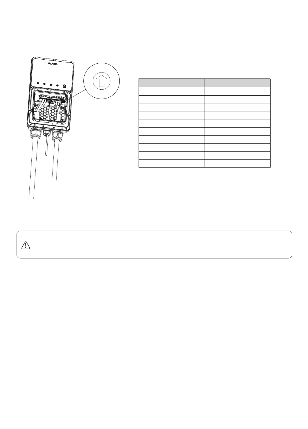
• Use 90 °C wire copper conductors only.
• Do not operate the equipment outside its operating tem-
perature range of -40 to 131 °F (-40 to 55 °C).
• Incorrect installation and testing of the equipment could
potentially damage the vehicle's battery, components,
and/or the equipment itself.
• Handle the equipment with care during transportation.
Do not subject it to strong force or impact or pull, twist,
tangle, drag or step on the equipment, to prevent
damage to it or any components.
IMPORTANT: Before operating or maintaining this equipment, please read these instructions carefully,
paying extra attention to the safety warnings and precautions. Failure to use this product properly may cause
damage and/or personal injury and will void the product warranty.
WARNING
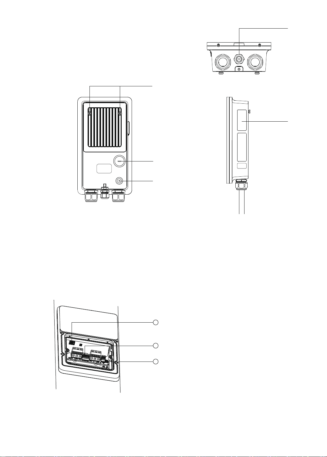
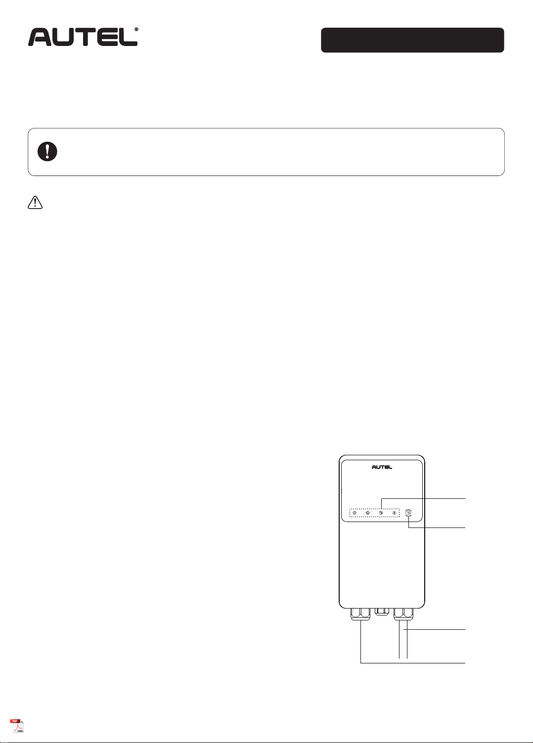
1. LED Indicators (from left to right)
MaxiCharger AC Wallbox Home
Product Overview
• Power LED
• Internet Connection LED
• Charging LED
• Bluetooth Connection LED
①
③
④
②
1
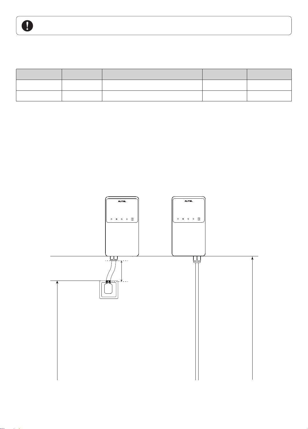
MaxiCharger AC Wallbox Home
(Separate Holster)
Maxi US AC W12-H
2. RFID LED
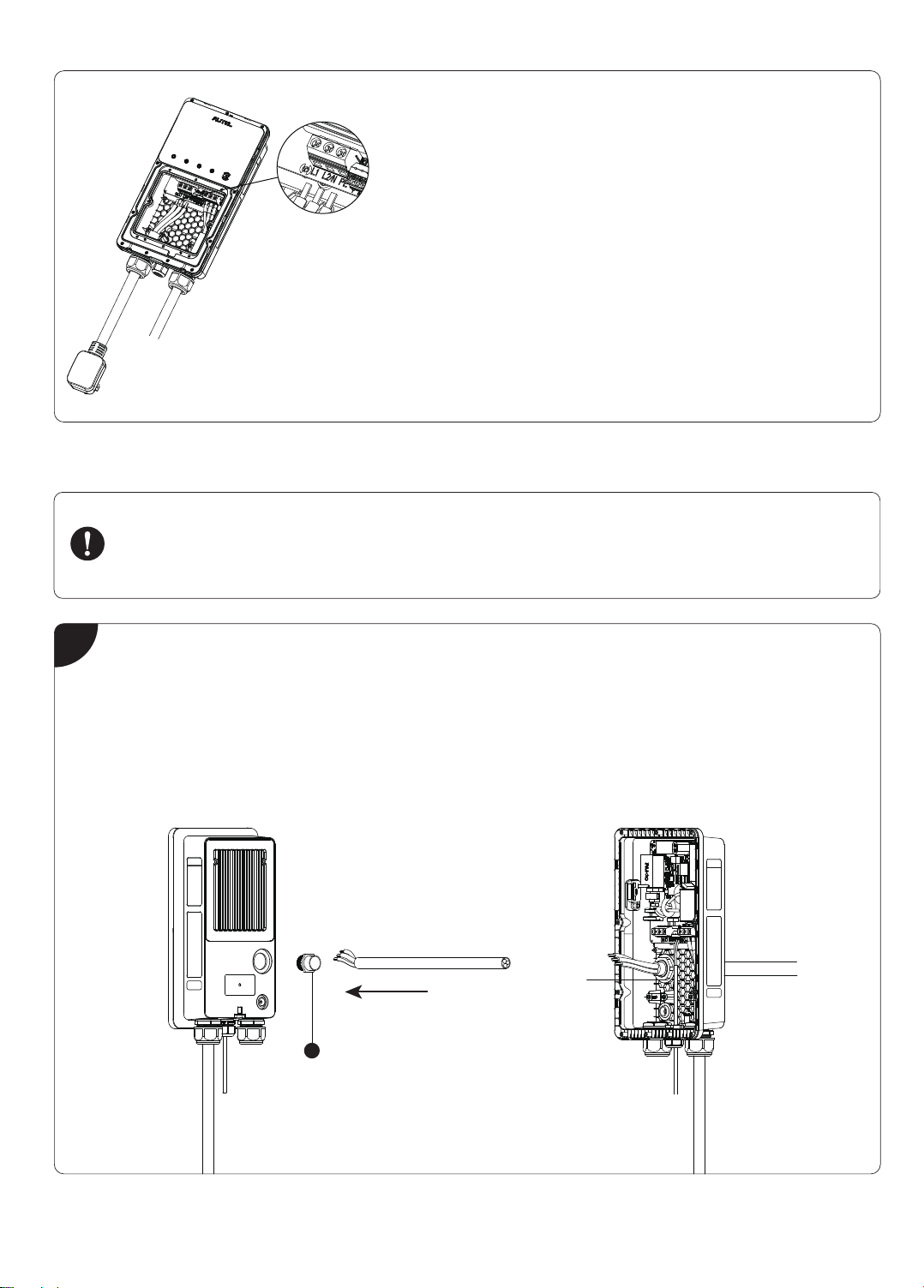
3. EV Charging Cable
4. Bottom AC Inlet Hole
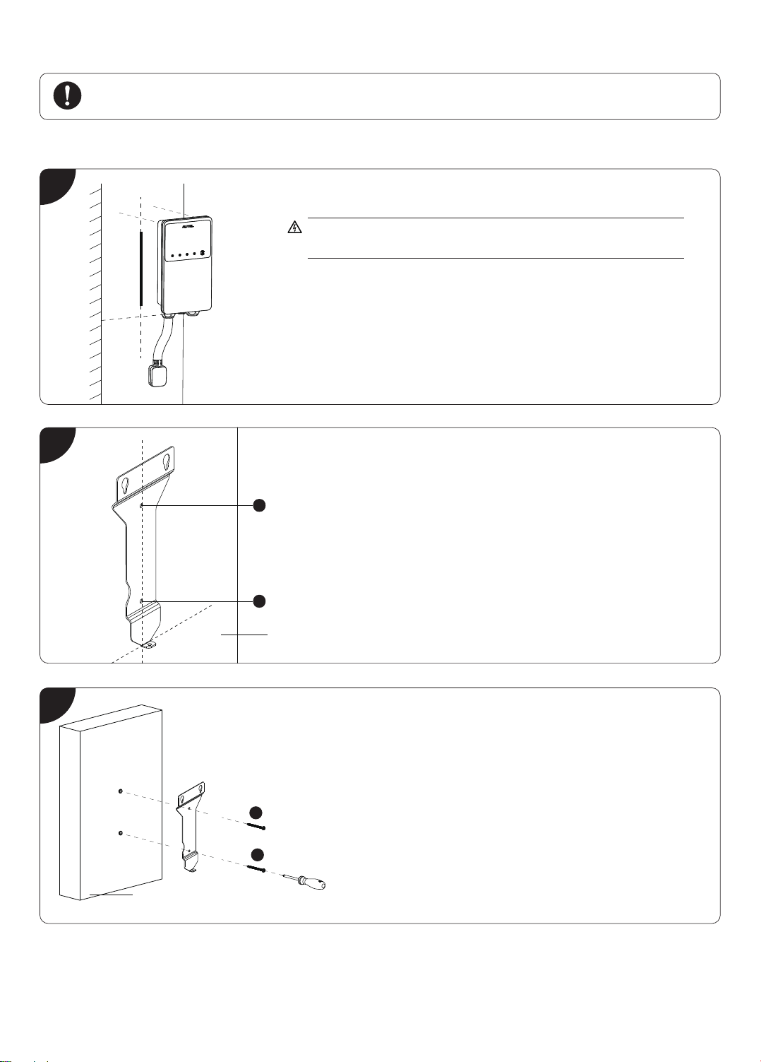
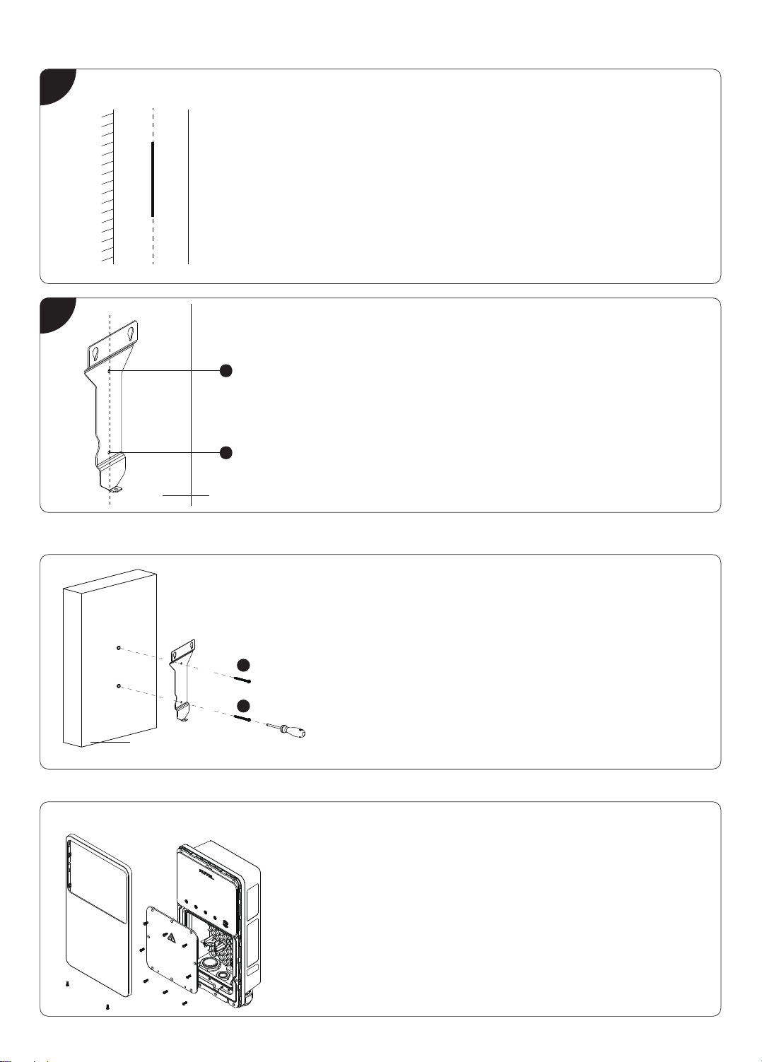
Installation Guide