manuals.online logo
Brands
  1. Home
  2. •
  3. Brands
  4. •
  5. Scosche
  6. •
  7. Automobile Accessories
  8. •
  9. Scosche FCJ1275A User manual

Scosche FCJ1275A User manual

1988-90 MERCURY TRACER
Radio Removal:
1. Remove three screws from the underside of the upper lip of the radio/
console trim panel.
2. Remove ashtray and remove two screws from inside the
ashtray cavity.
3. Gently unsnap the trim panel, disconnect the wiring and
remove the panel.
4. Remove four screws securing the radio pull the radio out of the
cavity and disconnect the wiring, and remove the radio.
Desmontaje del Radio:
1. Extraer los tres tornillos del lado inferior de la pestaña superior
de la moldura del radio en la consola.
2. Sacar el cenicero y extraer los dos tornillos que están dentro
de la cavidad del cenicero.
3. Desenganchar la moldura cuidadosamente, desenchufar los cables y sacar el panel.
4. Extraer los cuatro tornillos que fijan el radio, retirar el radio de la cavidad, desenchufar los cables y sacar el radio.
USE BRACKETS
SHOWN
Usar los
braquetes que se
muestran
USE THIN USE THIN
SPACER SPACER
Usar un Usar un
espaciador espaciador
delgado delgado
#1550 Panel
CUT LOWER BRACKETS ALONG CUT LINES
Cortar los braquetes inferiores a lo largo de las líneas de corte
TECH HELP 1-800-621-3695, ext. 3TECH HELP 1-800-621-3695, ext. 3
USE THE SHADED MOUNTING TABS AND THE INDICATED BRACKETS. CUT OFF THE REMAINING TABS AND DISCARD.
Usar las pestañas sombreadas y los braquetes indicados. Cortar las pestañas restantes y descartarlas.
1989-94 PLYMOUTH ACCLAIM
Radio Removal:
1. Carefully release the spring clips securing the radio/dash trim: three clips along the top and
two at the bottom. Disconnect the panel light and remove the trim piece.
2. Extract the two bolts securing the radio: one at the top right, and one at the bottom left of
the radio.
3. Pull the radio out of the dash cavity, disconnect the antenna
and all electrical connections, and remove the radio.
Desmontaje del Radio:
1. Soltar cuidadosamente los ganchos plásticos que fijan
la moldura del radio al tablero de instrumentos, tres en
la parte superior y tres en la parte inferior. Desenchufar
la luz del panel y sacar el panel.
2. Extraer los dos pernos que fijan el radio, uno arriba y a
la derecha sobre el radio y el otro a la izquierda y abajo
del radio.
3. Retirar el radio de la cavidad en el tablero, desenchufar
la antena, todas las conexiones eléctricas y de los
parlantes y sacar el radio.
USE THESE SUPPORT
TABS AS REQUIRED
Usar tantas de estas
pestañas como sea
necesario
USE THIS BRACKET
Usar este braquete
#2190 Panel
NOTE: INSTALLATION OF A
DIN UNIT MAY REQUIRE
DASH MODIFICATIONS.
NOTA: La instalación de
una unidad DIN puede
requerir modificar el
tablero del vehículo.
REMOVE
ALIGNMENT
PIN - BOTTOM
Sacar la clavija
de alineamiento
- Inferior
FCJ1275A
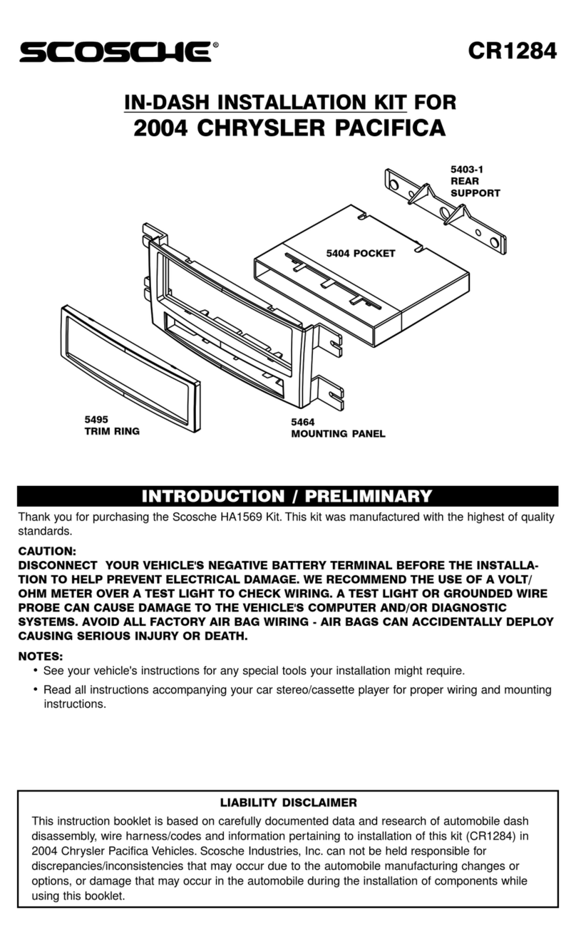
IN-DASH INSTALLATION KIT
FOR 1974-UP FORD/CHRYSLER/LINCOLN/
MERCURY AND JEEP VEHICLES
INTRODUCTION .................................. 2
PRELIMINARY PARTS LIST ................ 2
ASSEMBLING THE KIT ................... 2-5
FACTORY WIRE CODES ................ 5-7
CHRYSLER
1995-00 CIRRUS ............................. 8
1993-97 CONCORDE ...................... 8
1980-83 CORDOBA ......................... 9
1975-79 CORDOBA ......................... 9
1983-84 E CLASS .......................... 10
1990-93 FIFTH AVENUE ............... 10
1979-89 FIFTH AVENUE ............... 12
1990-93 IMPERIAL ........................ 10
1981-83 IMPERIAL ........................ 11
1984-86 LASER ............................. 11
1984-88 LE BARON ....................... 10
1982-83 LE BARON ....................... 12
1977-81 LE BARON ....................... 12
1987-93 LE BARON "COUPE" ....... 13
1990-95 LE BARON GTC .............. 13
1985-89 LE BARON GTS ............... 14
1989-94 LE BARON LANDAU ....... 14
1994-97 LHS .................................. 15
1979-81 NEWPORT ....................... 11
1975-78 NEWPORT ....................... 15
1994-97 NEW YORKER ................. 15
1988-93 NEW YORKER ................. 10
1984-87 NEW YORKER ................. 10
1979-83 NEW YORKER ................. 11
1975-78 NEW YORKER ................. 15
1995-00 SEBRING ......................... 16
1996-00 SEBRING "JXi"
CONVERTIBLE .................. 8
1996-00 TOWN & COUNTRY ........ 16
1994-95 TOWN & COUNTRY ........ 17
1991-93 TOWN & COUNTRY ........ 18
1990 TOWN & COUNTRY ........ 18
DODGE
1981-82 024 ................................... 19
1982-83 400 ................................... 12
1983-88 600 ES ............................. 10
1985-89 ARIES .............................. 10
1981-84 ARIES .............................. 12
1976-80 ASPEN ............................. 19
1995-00 AVENGER ........................ 16
1996-00 CARAVAN ........................ 16
1994-95 CARAVAN ........................ 17
1991-93 CARAVAN ........................ 18
1984-90 CARAVAN ........................ 18
1983-87 CHARGER ....................... 19
1974-78 CHARGER ....................... 20
1998-00 DAKOTA .......................... 20
1987-97 DAKOTA .......................... 21
1990-93 DAYTONA ........................ 21
1984-89 DAYTONA ........................ 11
1977-89 DIPLOMAT ....................... 12
This instruction booklet is based on carefully documented data and research of automobile dash disassembly, wire harness/codes and
information pertaining to installation of this kit (#FCJ1275A) in 1974-UP Ford, Chrysler, Lincoln, Mercury and Jeep Vehicles. Scosche
Industries, Inc. can not be held responsible for discrepancies/inconsistencies that may occur due to the automobile manufacturing
changes or options, or damage that may occur in the automobile during the installation of components while using this booklet.
DESLINDE DE RESPONSABILIDAD
Este manual de instrucciones está basado en información y estudios cuidadosamente documentados sobre el desmontaje de los
paneles de instrumentos, arneses y códigos de cables e información pertinente a la instalación de este juego (#FCJ1275A) en los
vehículos Ford, Chrysler, Lincoln, Mercury y Jeep a partir de 1974. Scosche Industries Inc. no puede ser responsable por discrepancias
o inconsistencias debido a cambios u opciones que pueda hacer el fabricante del vehículo, ni por daños que pudiesen ocurrirle al
automóvil durante la instalación de componentes debido al uso de este manual.
If you have any further questions call: TECH HELP 1-800-621-3695, ext. 3
Si usted tiene preguntas adicionales, por favor llamar
a la línea de teléfono gratuita del Departamento de
©2005 SCOSCHE INDUSTRIES, INC.
Soporte Técnico de Scosche 1-800-821-3695
SI 08/05 FCJ1275A (3000141)
TABLE OF CONTENTS
DODGE (Cont'd)
1998-00 DURANGO ....................... 20
1988-93 DYNASTY ........................ 10
1993-97 INTREPID .......................... 8
1985-89 LANCER .......................... 14
1978-79 MAGNUM XE ................... 20
1980-83 MIRADA ............................. 9
1974-78 MONACO ......................... 20
1995-99 NEON .............................. 22
1978-90 OMNI ............................... 19
1981-93 PICKUP ............................ 22
1974-80 PICKUP ............................ 23
1998-01 RAM ................................. 23
1994-97 RAM ................................. 24
1981-93 RAMCHARGER ............... 22
1974-80 RAMCHARGER ............... 23
1982-84 RAMPAGE ....................... 19
1974-78 ROYAL MONACO ............ 15
1987-94 SHADOW ......................... 24
1989-94 SPIRIT .............................. 25
1995-01 STRATUS ........................... 8
1979-81 ST. REGIS ........................ 11
1978-02 VAN .................................. 25
EAGLE
1993-97 VISION ............................... 8
FORD
1986-91 AEROSTAR ...................... 26
1987-91 BRONCO FULL SIZE ...... 26
1980-86 BRONCO-PICKUP ........... 27
1986-88 BRONCO II ...................... 28
1995-UP CROWN VICTORIA ......... 29
1984-90 ESCORT .......................... 30
1984-88 EXP .................................. 30
1997-02 EXPEDITION .................... 30
1995-UP EXPLORER 2DR SPORT ... 29
1995-01 EXPLORER 4DR .............. 29
2001-UP EXPLORER SPORT TRAC 29
1997-03 F-150 PICKUP ................. 30
1987-91 F-SERIES PICKUP ........... 26
1983-86 LTD .................................. 31
1979-82 LTD .................................. 31
1983-89 LTD CROWN VICTORIA .. 31
1985-86 MUSTANG ....................... 32
1995-UP RANGER PICKUP ............ 29
1985-88 RANGER .......................... 28
1986-89 TAURUS .......................... 33
1984-87 TEMPO ............................ 33
1983-88 THUNDERBIRD ............... 34
1980-82 THUNDERBIRD ............... 34
1975-91 VAN, E150/E250/E350 .... 29
JEEP
1997-01 CHEROKEE ..................... 35
1984-96 CHEROKEE ..................... 35
1986-92 COMMANCHE ................. 35
1996-98 GRAND CHEROKEE ....... 36
LIABILITY DISCLAIMER
JEEP (Cont'd)
1993-95 GRAND CHEROKEE ....... 36
1993 GRAND WAGONEER ...... 36
1987-91 GRAND WAGONEER ...... 35
1997-02 WRANGLER .................... 37
1986-95 WRANGLER .................... 37
LINCOLN
1995-97 CONTINENTAL ................ 29
1983-87 CONTINENTAL ................ 38
1984-89 CONTINENTAL
MARK VII LSC ................. 38
1995-98 MARK VIII ........................ 29
1995-97 TOWN CAR ...................... 29
1984-89 TOWN CAR ...................... 39
MAZDA
1995-UP B SERIES PICKUP .......... 29
MERCURY
1985-86 CAPRI .............................. 32
1983-88 COUGAR ......................... 34
1980-82 COUGAR XR-7 ................ 34
1995-UP GRAND MARQUIS .......... 29
1983-89 GRAND MARQUIS .......... 31
1984-87 LYNX ................................ 30
1983-86 MARQUIS ........................ 31
1979-82 MARQUIS ........................ 31
1996-01 MOUNTAINEER ............... 29
1986-89 SABLE ............................. 39
1983-87 TOPAZ ............................. 33
1988-90 TRACER .......................... 40
PLYMOUTH
1989-94 ACCLAIM ......................... 40
1996-00 BREEZE ............................. 8
1975-78 FURY ................................. 9
1982-89 GRAN FURY .................... 12
1975-77 GRAN FURY .................... 15
1978-90 HORIZON ........................ 19
1995-99 NEON .............................. 22
1985-89 RELIANT .......................... 10
1981-84 RELIANT .......................... 12
1983-84 SCAMP ............................ 19
1987-94 SUNDANCE ..................... 24
1981-82 TC3 .................................. 19
1981 TRAILDUSTER ................ 22
1974-80 TRAILDUSTER ................ 23
1983-87 TURISMO ........................ 19
1978-83 VAN .................................. 25
1976-80 VOLARE ........................... 19
1996-00 VOYAGER ........................ 16
1994-95 VOYAGER ........................ 17
1991-93 VOYAGER ........................ 18
1984-90 VOYAGER ........................ 18
USE THE SHADED MOUNTING TABS AND THE INDICATED BRACKETS. CUT OFF THE REMAINING TABS AND DISCARD.
FOR DIN ISO AND SHAFT RADIO INSTALLATION, SEE PAGES 4 & 5.
Usar las pestañas sombreadas y los braquetes indicados. Cortar las pestañas restantes y descartarlas.
Para la instalación de radios DIN ISO y radios que se montan por los ejes, ver las páginas 4 y 5.
40
INTRODUCTION - INTRODUCCIÓN
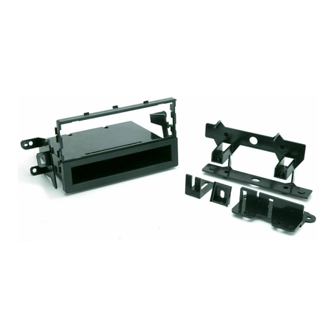
The Scosche in-Dash Installation Kit for 1974-UP Ford, Chrysler and Jeep Vehicles provides the parts
you need to mount your car stereo/cassette player into your vehicle's dash. Refer to the individual
instructions in this manual to remove your vehicle's factory installed radio.
El juego Scosche para Instalación en el Tablero para vehículos Ford, Chrysler y Jeep a partir de 1974
incluye todas las piezas necesarias para instalar el tocacasete estéreo en el tablero del vehículo.
Referirse a las instrucciones individuales en este manual para retirar el radio de fábrica instalado en
su vehículo.
PRELIMINARY PARTS LIST - LISTA PRELIMINAR DE PARTES
Your kit includes:
•3 Mounting Panels
• 2 Snap Shaft Tabs
• 2 “A” Brackets (Left & Right) El juego incluye:
• 2 “B” Brackets (Left & Right) •
3 Paneles de Montaje
• 2 “C” Brackets (Left & Right) •
2 Placas de sujeción para eje
• 2 Spacers •
2 Braquetes «A» (Derecho e Izquierdo)
• 1 Rear Support Bracket •
2 Braquetes «B» (Derecho e Izquierdo)
• 1 Hardware Pack •
2 Braquetes «C» (Derecho e Izquierdo)
• 2 Tracer Bracket Spacers
CAUTION: CUIDADO:
Disconnect your vehicle's negative battery cable
Desconectar el cable negativo de la batería
before removing the radio/proceeding with
del vehículo antes de retirar el radio o
installation.
proceder con la instalación.
NOTES: NOTAS:
• See your vehicle's instructions for any special
• Ver las instrucciones del vehículo para
tools your installation might require.
determinar si se necesita alguna
• Read all instructions accompanying your car
herramienta especial.
stereo/cassette player for proper wiring and
• Leer todas las instrucciones que
mounting instructions.
acompañan el estéreo/tocacasete del
vehículo para el cableado y montaje
apropiado.
ASSEMBLING THE KIT - ENSAMBLAJE DEL JUEGO
Use the shaded mounting tabs and indicated brackets. Carefully break or cut off the unused brackets,
Then assemble the radio and the mounting panel as shown below, and secure the kit to your dash
using the supplied screws. Reassemble your dash, and attach the radio's front panel and controls.
The following example shows a typical installation.
Usar las pestañas sombreadas y los braquetes
indicados. Separar o cortar cuidadosamente los
braquetes que no se usen. Luego ensamblar el
radio y el panel de montaje como se muestra a
continuación, y fijar el juego al tablero del
vehículo con los tornillos que se proveen.
Reensamblar el tablero y colocarle el
panel frontal y los controles del radio.
El siguiente ejemplo muestra una
instalación típica.
1984-89 LINCOLN TOWN CAR
Radio Removal:
1. Remove three screws from the radio trim below the dash.
2. Open out the 1-1/2" wide plastic trim piece above the radio trim.
3. Remove three screws from behind the trim. Remove the instrument cluster trim panel.
4. Remove three screws which secure the radio and the radio brackets to dash.
5. Disconnect the two wiring harnesses, antenna lead, and harness retaining clip. Remove the radio.
Desmontaje del Radio:
1. Extraer los tres tornillos de la moldura bajo el tablero.
2. Abrir la moldura de plástico de 1 1/2" de ancho que está sobre el radio.
3. Extraer tres tornillos que están detrás de la moldura. Sacar la moldura del panel de instrumentos.
4. Extraer los tres tornillos que fijan el radio y sus braquetes de soporte al tablero y retirar el radio de la cavidad.
5. Desenchufar los arneses eléctricos, el cable de la antena y el sujetador del arnés. Sacar el radio.
USE
THIS "B"
USE
THIS "B"
BRACKET BRACKET
Usar este
braquete
Usar este
braquete
#2190 Panel
SECURE THE BRACKETS TO THE BOSSES LOCATED ON THE
NOTE: INSTALLATION OF A DIN UNIT BACK SIDE OF THE KIT WITH THE SUPPLIED HARDWARE. SEE
MAY REQUIRE DASH MODIFICATIONS. PAGE 4.
NOTA: La instalación de una unidad Asegurar los braquetes en sus ranuras en la parte posterior del
DIN puede requerir modificar el juego usando los tornillos autoenroscantes provistos. Ver la
tablero del vehículo. página 4.
USE THE SHADED MOUNTING TABS AND THE INDICATED BRACKETS. CUT OFF THE REMAINING TABS AND DISCARD.
FOR DIN ISO AND SHAFT RADIO INSTALLATION, SEE PAGES 4 & 5.
Usar las pestañas sombreadas y los braquetes indicados. Cortar las pestañas restantes y descartarlas.
Para la instalación de radios DIN ISO y radios que se montan por los ejes, ver las páginas 4 y 5.
1986-89 MERCURY SABLE
Radio Removal:
1. Carefully pull on the edges of the radio trim panel
to release the plastic clips, and remove the trim
panel.
2. Remove four screws which secure the radio to the
dashboard, slide the radio out of the dash,
disconnect the harnesses and antenna, then
remove radio.
Desmontaje del Radio:
1. Halar cuidadosamente los bordes de la moldura
del radio para soltar los ganchos plásticos y sacar
la moldura.
2. Extraer los cuatro tornillos que fijan el radio al
tablero, deslizar el radio fuera de la cavidad ,
desenchufar los arneses, la antena y sacar el
radio.
Usar este
braquete
#1550 Panel
USE THIS BRACKET
Usar este braquete
USE THIS
BRACKET
USE THE SHADED MOUNTING TABS AND THE INDICATED BRACKETS. CUT OFF THE REMAINING TABS AND DISCARD.
Usar las pestañas sombreadas y los braquetes indicados. Cortar las pestañas restantes y descartarlas.
2 39
ASSEMBLING THE KIT - ENSAMBLAJE DEL JUEGO (Cont'd)
1983-87 LINCOLN CONTINENTAL
USE
braquete
NOTE: INSTALLATION
OF A DIN UNIT MAY
REQUIRE DASH
MODIFICATIONS.
NOTA: La instalación de
una unidad DIN puede
requerir modificar el
tablero del vehículo.
Radio Removal:
1. Remove two screws from below the radio.
2. Open the ashtray and remove the two outside screws. Carefully pull the
radio trim panel off.
3. Remove four screws securing the radio bracket to the dash. Carefully
pull the radio out.
4. Disconnect the power, antenna, speakers, and all electrical leads.
Remove the radio.
Desmontaje del Radio:
1. Extraer los dos tornillos que están debajo del radio.
2. Abrir el cenicero y extraer los dos tornillos
exteriores. Halar la moldura del radio cuidadosamente y sacarla.
3. Extraer los cuatro tornillos que fijan el braquete del radio al tablero y retirar
el radio de la cavidad.
4. Desenchufar la antena, todas las conexiones eléctricas y de los
parlantes y sacar el radio.
#2190 Panel
SECURE THE BRACKETS TO THE BOSSES LOCATED ON THE BACK SIDE OF THE KIT
WITH THE SUPPLIED HARDWARE. SEE PAGE 4.
Asegurar los braquetes en sus ranuras en la parte posterior del juego usando los
tornillos autoenroscantes provistos. Ver la página 4.
USE THE SHADED MOUNTING TABS AND THE INDICATED BRACKETS. CUT OFF THE REMAINING TABS AND DISCARD.
FOR DIN ISO AND SHAFT RADIO INSTALLATION, SEE PAGES 4 & 5.
Usar las pestañas sombreadas y los braquetes indicados. Cortar las pestañas restantes y descartarlas.
Para la instalación de radios DIN ISO y radios que se montan por los ejes, ver las páginas 4 y 5.
1984-89 LINCOLN CONTINENTAL MARK VII LSC
Radio Removal:
1. Carefully pull on the edges of the aluminum radio trim panel to release the clips, and remove the trim panel.
2. Remove four screws which secure the radio to the dash, and slide the radio out of the dash.
3. Disconnect the power, antenna, and all speaker and electrical connections. Remove the radio.
Desmontaje del Radio:
1. Halar cuidadosamente los bordes de la moldura de aluminio del radio y sacarla del panel.
2. Extraer los cuatro tornillos que fijan el radio al tablero, deslizar el radio fuera de la cavidad.
3. Desenchufar la antena, todas las conexiones eléctricas y de los parlantes y sacar el radio.
TRIM LINE
Línea de
#2190 Panel
corte
USE
BRACKET
THIS "B"
BRACKET
USE
THIS "B"
BRACKET
Usar este
braquete
THIS "B"
USE
THIS "B"
Usar este
BRACKET
Usar este
braquete
Usar este braquete
TRIM LINE
Línea de
corte
NOTE: INSTALLATION OF A DIN UNIT MAY REQUIRE DASH MODIFICATIONS.
NOTA: La instalación de una unidad DIN puede requerir modificar el tablero del vehículo.
SECURE THE BRACKETS TO THE BOSSES LOCATED ON THE BACK
SIDE OF THE KIT WITH THE SUPPLIED HARDWARE. SEE PAGE 4.
Asegurar los braquetes en sus ranuras en la parte posterior del juego
usando los tornillos autoenroscantes provistos. Ver la página 4.
USE THE SHADED MOUNTING TABS AND THE INDICATED BRACKETS. CUT OFF THE REMAINING TABS AND DISCARD.
FOR DIN ISO AND SHAFT RADIO INSTALLATION, SEE PAGES 4 & 5.
Usar las pestañas sombreadas y los braquetes indicados. Cortar las pestañas restantes y descartarlas.
Para la instalación de radios DIN ISO y radios que se montan por los ejes, ver las páginas 4 y 5.
38
The instructions for each vehicle show which mounting panel and brackets to use.
Las instrucciones para cada vehículo muestran cual panel de montaje y cuales braquetes se deben
usar.
TOWN & COUNTRY
TEMPO/TOPAZ CARAVAN VOYAGER
AS REQUIRED CHRYSLER/STRATUS
necesario Usar tantos braquetes
como se requieran
LTD/RANGER
FORD VAN
Camioneta
Van
LTD/RANGER
FORD VAN
Camioneta Van
para eje SNAP SHAFT TAB
Placa de sujeción
para eje
CARAVAN VOYAGER
LEFT "L" SPACER
Espaciador Izquierdo «L»
TEMPO/TOPAZ
ESCORT
GRAND CHEROKEE/
AVENGER/SEBRING
BOTTOM
Inferior
ESCORT
MUSTANG
PICKUP
TOWN & COUNTRY
LEFT "L" SPACER
Espaciador Derecho «R»
USE CIRRUS/
BRACKETS AS
REQUIRED
CHRYSLER
CIRRUS/STRATUS
MUSTANG
USE SUPPORT TABS
Usar tantas de estas
pestañas como sea
GRAND CHEROKEE/
AVENGER/SEBRING
TOP - Superior
SNAP SHAFT TAB
Placa de sujeción
#2190
PANEL
PICKUP/
BRONCO
FORD REAR SUPPORT #2189
Ford Soporte Posterior #2189
DIN + 1/2
panel #2215
#2215
PANEL
Abrazadera
2521-L 2531-R
BRACKET BRACKET
Abrazadera
#2521-L #2521-R
2531-R
2531-L BRACKET
BRACKET Abrazadera
Abrazadera #2531-R
#2531-L
Ford/Lincoln/
FORD/LINCOLN/
Mercury spacer
MERCURY
Espaciador
SPACER
Espaciador
BRONCO PICKUP BRONCO/PICKUP
CHEROKEE/
CHEROKEE/
COMANCHE/
COMANCHE/
GRAND
GRAND
WAGONEER
TRACER TRACER
WAGONEER
3
TRACER
TAURUS/
SABLE
TRACER
TAURUS/SABLE
WRANGLER
#1550
PANEL
ASSEMBLING THE KIT - ENSAMBLAJE DEL JUEGO (Cont'd)
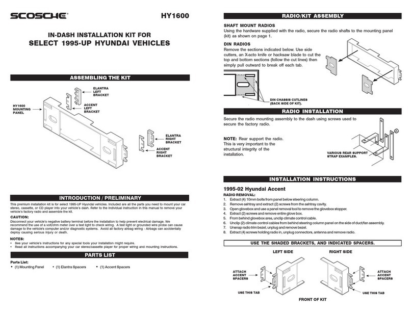
ATTACHING THE BRACKET(S):
Some installations require that you attach specific bracket(s).
Using the supplied self tapping screws, secure the specified
bracket(s) to the bosses on the back of the mounting panel.
FIJANDO EL(LOS)
BRAQUETE(S):
Algunas instalaciones requieren colocar
un(os) braquete(s) específico(s).
Asegurar el(los) braquete(s)
especificado(s) en su(s) la(s) ranura(s)
en la parte posterior del panel de
montaje usando los tornillos
autoenroscantes provistos.
USING SCREWS SUPPLIED, SECURE
THE NECESSARY BRACKET(S) TO THE
BOSSES LOCATED ON THE BACK OF
THE MOUNTING PANEL.
SHAFT MOUNT RADIOS:
BACK OF MOUNTING PANEL
Parte posterior del panel de montaje
ESCORT/PICKUP BRACKET
Braquete
Usando los tornillos que se proveen,
asegurar el(los) braquete(s)
especificado(s) en su(s) ranura(s) en
la parte posterior del panel de
montaje.
Using the radio's knobs/hardware, secure the radio to the mounting panel and to the shaft radio
faceplate as shown.
RADIOS QUE SE MONTAN POR LOS EJES:
Usando las perillas de control del radio y sus elementos, fijar el radio al panel de montaje y a la placa
frontal del radio como se muestra.
#1550
MOUNTING PANEL
Panel de montaje
SHAFT RADIO
SPACER (OPTIONAL)
Espaciador del eje del
radio (Opcional)
SHAFT RADIO'S
SUPPLIED FACEPLATE
Eje Placa frontal
provista para los ejes
del radio
#2215 DIN + 1/2
MOUNTING PANEL
Panel de montaje
SHAFT RADIO'S SUPPLIED FACEPLATE
Eje Placa frontal provista para los ejes
del radio
4
CAUTION: CUIDADO:
REAR SUPPORT IS El soporte posterior
ESSENTIAL TO THE es esencial para la
INSTALLATION'S integridad
STRUCTURAL estructural de la
INTEGRITY. instalación.
REAR SUPPORT STRAP
Tirante de soporte
posterior
#2190
MOUNTING PANEL
Panel de montaje
SNAP SHAFT TABS
Placa de sujeción para eje
FORD REAR
SUPPORT STRAP
Tirante de soporte
posterior
1997-02 JEEP WRANGLER
Radio Removal:
1. Extract (2) screws from dash bezel.
2. Pry on bezel to release spring clips and remove.
3. Extract (2) screws holding radio, unplug and remove.
Desmontaje del Radio:
1.
Extraiga dos (2) tornillos del besel del tablero.
2. Apalánquese en el besel para liberar las graspas de seguridad y quítelo.
3. Extraiga dos (2) tornillos que sujetan el radio, desconectelo y quítelo.
REMOVE
ALIGNMENT
USE THESE SUPPORT PIN - BOTTOM
TABS AS REQUIRED #2190 Panel Sacar la clavija
Usar tantas de estas de alineamiento
pestañas como sea - Inferior
necesario
USE THIS BRACKET
Usar este braquete
USE THE SHADED MOUNTING TABS AND THE INDICATED BRACKETS. CUT OFF THE REMAINING TABS AND DISCARD.
FOR DIN ISO AND SHAFT RADIO INSTALLATION, SEE PAGES 4 & 5.
Usar las pestañas sombreadas y los braquetes indicados. Cortar las pestañas restantes y descartarlas.
Para la instalación de radios DIN ISO y radios que se montan por los ejes, ver las páginas 4 y 5.
1986-95 JEEP WRANGLER
Radio Removal:
1. Remove three screws from the lower edge of the dash trim.
2. Extract three screws from the upper edge of the dash trim.
3. Remove the dash trim.
4. If the vehicle is not equipped with a factory radio, remove two
screws securing the pocket and remove the pocket. If the
vehicle is equipped with a factory radio, remove two screws
from the radio mounting bracket.
5. Pull the radio out of the cavity, disconnect all electrical
connections, then remove the radio.
Desmontaje del Radio:
1. Extraer los tres tornillos del borde inferior de
la moldura del tablero.
2. Extraer los tres tornillos del borde superior de
la moldura del tablero.
3. Sacar la moldura del tablero.
4. Si el vehículo no está equipado con radio de
fábrica, extraer los dos tornillos que fijan el
compartimiento y sacarlo. Si el vehículo está
equipado con radio de fábrica, extraer los dos
tornillos del braquete de soporte del radio.
5. Retirar el radio de la cavidad, desenchufar
todas las conexiones y sacar el radio.
USE THESE BRACKETS
Usar estos braquetes
#1550 Panel
USE THE SHADED MOUNTING TABS AND THE INDICATED BRACKETS. CUT OFF THE REMAINING TABS AND DISCARD.
Usar las pestañas sombreadas y los braquetes indicados. Cortar las pestañas restantes y descartarlas.
37
-
11
11
22
22
33
33
44
44
55
55
66
66
77
77
11
11
22
22
33
33
44
44
55
55
66
66
77
77
11
11
22
22
33
33
44
44
55
55
66
66
77
77
11
11
22
22
33
33
44
44
55
55
66
66
77
77
ASSEMBLING THE KIT - ENSAMBLAJE DEL JUEGO (Cont'd)
FACTORY WIRING CODES CÓDIGO DE CABLES DE FÁBRICA
NOTE: • All wire codes are viewed as looking at the front of the plug with the wires exiting the rear.
• Use these wiring codes as a quide. Your vehicle might differ.
NOTA: • Todos los códigos de los cables se leen mirando al frente del conector con los cables saliendo
por atrás.
• Usar estos códigos de los cables como guía. Su vehículo puede ser diferente.
7
6
5
4
3
2
1
1
2
3
4
5
6
7
1996-98 JEEP GRAND CHEROKEE
Radio Removal:
1. Extract (5) screws from along top of dash instrument bezel.
2. Carefully pop out wood grain trim panel around a/c heater control.
3. Carefully pop out wood grain trim panel around headlight switch.
4. Extract (4) screws from along bottom of dash instrument bezel,
lift up and away to remove.
5. Extract (2) 3/8" hex heard bolts holding radio, unplug
connectors and remove.
Desmontaje del Radio:
1. Extraiga (5) tornillos sobre la parte superior en el bisel del
tablero de instrumentos.
2. Desprenda con cuidado el panel de grano de madera
alrededor del control del aire acondicionado y calefacción.
3. Desprenda con cuidado el panel de grano de madera alrededor del
interruptor de luces delanteras.
4. Extraiga (4) tornillos sobre la parte inferior en el bisel del tablero de instrumentos, desprenda y remueva.
5. Extraiga (2) pernos de 3/8 “ con cabeza hexagonal que sostienen el radio, desconecte los cables y remueva.
USE THESE SUPPORT REMOVE
TABS AS REQUIRED ALIGNMENT
Usar tantas de estas PIN - BOTTOM
pestañas como sea Sacar la clavija
necesario de alineamiento
- Inferior
USE THIS BRACKET
Usar este braquete
#2190 Panel
IN-DASH DIN PULLOUT, DETACHABLE FACEPLATE, (DIN-E) RADIOS
Remove the sections indicated below. Use side cutters, an X-acto knife or hacksaw blade to cut the
top and bottom sections (follow the cut lines) then simply pull outward to break off each tab.
RADIOS (DIN-E) DESMONTABLES CON PLACA FRONTAL REMOVIBLE PARA
INSTALAR EN EL TABLERO
Retirar las secciones que se muestran a continuación. Cortar las secciones superior e inferior usando
cortadores laterales, una cuchilla de precisión u hoja de sierra (seguir las líneas para cortar). Luego
simplemente tirar hacia afuera para soltar de las pestañas.
DIN RADIO
Radio Din
CAUTION:
rear support is
essential to the
installation's struc-
tural integrity.
CUIDADO:
El soporte posterior es
esencial para la integridad
estructural de la instalación.
DIN CHASSIS
CUTLINES
(BACKSIDE OF
KIT)
Líneas de corte
para chasis DIN
(Parte posterior
del juego) REAR SUPPORT
STRAP
Tirante de soporte
posterior
RADIO'S MOUNTING SLEEVE
Manga de montaje del radio
RADIO'S SUPPLIED TRIMPLATE
Moldura suministrada con el radio
#2190
MOUNTING PANEL
Panel de montaje
#1550 PANEL
USE THE SHADED MOUNTING TABS AND THE INDICATED BRACKETS. CUT OFF THE REMAINING TABS AND DISCARD.
Usar las pestañas sombreadas y los braquetes indicados. Cortar las pestañas restantes y descartarlas.
1993-95 JEEP GRAND CHEROKEE
1993 JEEP GRAND WAGONEER
Radio Removal:
1. Extract two screws from above the radio securing the radio trim bezel.
2. Extract two screws from above the diagnostics display panel securing
the radio trim bezel.
3. Carefully remove the ashtray and extract two screws located in the
ashtray cavity securing the radio trim bezel.
4. Pull the radio trim bezel away from the dash, unplug all connectors
and remove the bezel.
5. Extract two nuts securing the radio to the dash, and pull the radio
from the cavity; unplug all connectors and remove the radio.
Desmontaje del Radio:
1. Extraer los dos tornillos ubicados sobre el
radio que fijan la moldura del radio.
2. Extraer los dos tornillos ubicados sobre
panel indicador de diagnósticos que fijan la
moldura del radio.
3. Retirar el cenicero cuidadosamente y
Usar este
extraer los dos tornillos ubicados en la
cavidad que aseguran la moldura del radio.
(Superior)
4. Retirar la moldura del radio alejándola del
tablero, desenchufar todos los conectores
y sacar la moldura.
5. Extraer las dos tuercas que aseguran el
radio al tablero y retirar el radio de la
cavidad, desenchufar todos los conectores
y sacar el radio.
USE THIS
BRACKET
USE THIS BRACKET (BOTTOM)
Usar este braquete (Inferior)
USE THE SHADED MOUNTING TABS AND THE INDICATED BRACKETS. CUT OFF THE REMAINING TABS AND DISCARD.
FOR DIN ISO AND SHAFT RADIO INSTALLATION, SEE PAGES 4 & 5.
Usar las pestañas sombreadas y los braquetes indicados. Cortar las pestañas restantes y descartarlas.
Para la instalación de radios DIN ISO y radios que se montan por los ejes, ver las páginas 4 y 5.
36
1984-UP CHRYSLER VEHICLES
Gray Connector - Power/Speaker:
1 = 12 Volt Battery/Constant (12V+)
2 = 12 Volt Ignition/Switched (12V+)
3 = Radio Light
4 = Memory Light
5 = Right Front Negative (RF-)
6 = Left Front Negative (LF-)
7 = Not Used
Conector Gris - Energía/Parlantes:
1 = +12V Constante, Batería
2 = +12V Contacto encendido
3 = Luz de radio
4 = Luz de memoria
5 = Derecho frontal negativo
6 = Izquierdo frontal negativo
7 = Disponible
Black Connector - Speaker:
1 = Right Rear Negative (RR-)
2 = Left Rear Negative (LR-)
3 = Right Front Positive (RF+)
4 = Left Front Positive (LF+)
5 = Right Rear Positive (RR+)
6 = Left Rear Positive (LR+)
7 = Power Antenna
Conector Negro - Parlante:
1 = Derecho posterior negativo
2 = Izquierdo posterior negativo
3 = Derecho frontal positivo
4 = Izquierdo frontal positivo
5 = Derecho posterior positivo
6 = Izquierdo posterior positivo
7 = Antena eléctrica
5
(TOP)
braquete
#2190 Panel
FACTORY WIRING CODES CÓDIGO DE CABLES DE FÁBRICA
1988-UP JEEP VEHICLES
Power and Speaker Connectors:
1 = Left Rear Negative (LR-)
2 = Left Front Negative (LF-)
3 = LCD Dimmer
4 = Illumination/Dimmer (+12V Variable)
5 = Right Front Negative (RF-)
6 = Right Rear Negative (RR-)
7 = Left Rear Positive (LR+)
8 = Left Front Positive (LR+)
9 = Power Antenna Trigger
10 = 12 Volt Battery/Constant (12V+)
11 = 12 Volt Ignition/Switched (12V+)
12 = Right Front Positive (RF+)
13 = Right Rear Positive (RR+)
7 8 9
Conectors de energía y parlantes:
1 = Izquierdo posterior negativo
2 = Izquierdo frontal negativo
3 = Atenuador de luces del tablero
4 = Atenuador de iluminación
5 = Derecho frontal negativo
6 = Derecho posterior negativo
7 = Izquierdo posterior positivo
8 = Izquierdo frontal positivo
9 = Actuador de antena eléctrica
10 = +12V Constante, Batería
11 = +12V Contacto Encendido
12 = Derecho frontal positivo
13 = Derecho posterior positivo
1 2 3 4 5 6
10 11 12 13
1986-UP FORD VEHICLES
Gray Connector - Power/Speaker: Black Connector - Speaker:
A = 12 Volt Battery/Constant (12V+) A = Left Front Positive (LF+)
B = Not Used B = Left Front Negative (LF-)
C = 12 Volt Ignition/Switched (12V+) C = Left Rear Positive (LR+)
D = Illumination D = Left Rear Negative (LR-)
E = LCD E = Right Front Positive (RF+)
F = Chassis Ground (12V-) F = Right Front Negative (RF-)
G = Power Antenna G = Right Rear Positive (RR+)
H = Remote Turn On (Factory Amplifier) H = Right Rear Negative (RR-)
Conector Gris - Energía/Parlantes: Conector Negro - Parlante:
A = +12V Constante, Batería A = Izquierdo frontal positivo
B = Disponible B = Izquierdo frontal negativo
C = +12V Contacto encendido C = Izquierdo posterior positivo
D = Iluminación D = Izquierdo posterior negativo
E = Luces del tablero E = Derecho frontal positivo
F = Conexión a tierra F = Derecho frontal negativo
G = Antena eléctrica G = Derecho posterior positivo
H = Encendido remoto (Amplificador de fábrica) H = Derecho posterior negativo
H G F E D C B A H G F E D C B A
1997-01 JEEP CHEROKEE
Radio Removal:
1. Pop out dash bezel bottom first and remove.
2. Extract (2) screws holding radio, unplug and remove.
Desmontaje del Radio:
1.
l. Primero haga botar hacia fuera la parte inferior del besel del tablero, y quítelo.
2. Extraiga dos (2) tornillos que sujetan el radio, desconectelo y quítelo.
#2190 Panel
USE THESE SUPPORT
TABS AS REQUIRED
Usar tantas de estas
pestañas como sea
necesario
USE THIS BRACKET
Usar este braquete
REMOVE
ALIGNMENT
PIN - BOTTOM
Sacar la clavija
de alineamiento
- Inferior
USE THE SHADED MOUNTING TABS AND THE INDICATED BRACKETS. CUT OFF THE REMAINING TABS AND DISCARD.
FOR DIN ISO AND SHAFT RADIO INSTALLATION, SEE PAGES 4 & 5.
Usar las pestañas sombreadas y los braquetes indicados. Cortar las pestañas restantes y descartarlas.
Para la instalación de radios DIN ISO y radios que se montan por los ejes, ver las páginas 4 y 5.
1984-96 JEEP CHEROKEE
1986-92 JEEP COMANCHE
1987-91 JEEP GRAND WAGONEER
Radio Removal:
1. Remove two screws from the instrument panel, one from
above the cigarette lighter, and one from above the
headlight switch. Unsnap and remove the lower steering
column trim piece and remove the trim panel.
2. If equipped with a factory radio, remove the two screws
securing the radio brackets to the dashboard.
3. Pull the radio out of the cavity, disconnect all electrical
connections, then remove the radio.
Desmontaje del Radio:
1. Sacar los dos tornillos del panel de instrumentos, uno sobre el encendedor de cigarrillos y el otro sobre el interruptor
de las luces delanteras. Desenganchar y sacar la moldura bajo la columna del volante y sacarla.
2. Si estuviese equipado con radio de fábrica, sacar los dos tornillos que fijan los braquetes del radio al tablero.
3. Retirar el radio de la cavidad, desenchufar todos los conectores eléctricos y sacar el radio.
-
11
11
22
22
33
33
44
44
55
55
66
66
77
77
88
88
99
99
11
1100
00
11
1111
11
11
1122
22
11
1133
33
11
11
22
22
33
33
44
44
55
55
66
66
77
77
88
88
99
99
11
1100
00
11
1111
11
11
1122
22
11
1133
33
AA
AA AA
AA
BB
BB BB
BB
CC
CC CC
CC
DD
DD DD
DD
EE
EE EE
EE
FF
FF FF
FF
GG
GG GG
GG
HH
HH HH
HH
AA
AA AA
AA
BB
BB BB
BB
CC
CC CC
CC
DD
DD DD
DD
EE
EE EE
EE
FF
FF FF
FF
GG
GG
HH
HH HH
HH USE BRACKETS SHOWN
Usar los braquetes que
se muestran.
#1550 Panel
USE THE SHADED MOUNTING TABS AND THE INDICATED BRACKETS. CUT OFF THE REMAINING TABS AND DISCARD.
Usar las pestañas sombreadas y los braquetes indicados. Cortar las pestañas restantes y descartarlas.
6 35
-
AA
AA
1.1.
1.1. AA
AA
BB
BB
BB
BB
CC
CC
CC
CC
DD
DD
DD
DD
2.2.
2.2. AA
AA
BB
BB
CC
CC
DD
DD
3.3.
3.3. AA
AA
AA
AA
BB
BB AA
AA
CC
CC
DD
DD
4.4.
4.4. AA
AA
AA
AA
BB
BB
BB
BB
CC
CC
CC
CC
::
::
Gray Connector - Speaker:Gray Connector - Speaker:
11
11
22
22
33
33
44
44
55
55
66
66
77
77
88
88
11
11
22
22
33
33
44
44
11
11
22
22
33
33
44
44
55
55
66
66
77
77
88
88
11
11
22
22
33
33
44
44
FACTORY WIRING CODES CÓDIGO DE CABLES DE FÁBRICA
1982-86 FORD VEHICLES
1983-88 FORD THUNDERBIRD
1983-88 MERCURY COUGAR
Radio Removal:
1. Remove two screws from the pocket between the ashtray and radio trim. Remove the pocket.
2. Remove four screws from the radio trim: two from the top, and two from the bottom edge.
3. Remove the radio trim.
4. Remove four screws retaining the radio and remove the radio. Disconnect the power, antenna and all speaker and
electrical connections.
Desmontaje del Radio:
1. Extraer los dos tornillos del compartimiento entre el cenicero y la moldura del radio y sacarlo.
2. Extraer los cuatro tornillos de la moldura del radio, dos del borde superior y dos del borde inferior.
3. Sacar la moldura del radio.
4. Extraer los cuatro tornillos que fijan el radio y retirar el radio.
los parlantes.
USE
THIS "B"
USE
THIS "B"
BRACKET BRACKET
Usar este
braquete
Usar este
braquete
Desenchufar la antena y todas las conexiones eléctricas y de
SECURE THE BRACKETS TO THE BOSSES LOCATED ON THE
#2190 Panel
NOTE: INSTALLATION OF A DIN UNIT MAY BACK SIDE OF THE KIT WITH THE SUPPLIED HARDWARE.
REQUIRE DASH MODIFICATIONS. SEE PAGE 4.
NOTA: La instalación de una unidad DIN Asegurar los braquetes en sus ranuras en la parte posterior
puede requerir modificar el tablero del del juego usando los tornillos autoenroscantes provistos.
vehículo. Ver la página 4.
USE THE SHADED MOUNTING TABS AND THE INDICATED BRACKETS. CUT OFF THE REMAINING TABS AND DISCARD.
FOR DIN ISO AND SHAFT RADIO INSTALLATION, SEE PAGES 4 & 5.
Usar las pestañas sombreadas y los braquetes indicados. Cortar las pestañas restantes y descartarlas.
Para la instalación de radios DIN ISO y radios que se montan por los ejes, ver las páginas 4 y 5.
1980-82 FORD THUNDERBIRD
1980-82 MERCURY COUGAR XR-7
Radio Removal:
1. Remove three screws inside the ashtray from the radio trim panel.
2. Remove the radio knobs, pull the trim panel out from the bottom and remove it.
3. Remove four screws securing the radio mounting bracket to the dash, and pull the assembly out.
4. Disconnect the power, antenna, and all speaker and electrical connections.
Desmontaje del Radio:
1. Extraer los tres tornillos de la moldura del radio que están dentro del cenicero.
2. Sacar las perillas del radio, sacar la moldura del radio halándola de la parte inferior.
3. Extraer los cuatro tornillos que fijan el braquete del radio al tablero y retirar el radio de la cavidad.
4. Desenchufar la antena y todas las conexiones eléctricas y de
los parlantes.
USE
THIS "B"
USE
THIS "B"
BRACKET BRACKET
Usar este
braquete
Usar este
braquete
SECURE THE BRACKETS TO THE BOSSES LOCATED ON THE
NOTE: INSTALLATION OF A DIN UNIT MAY BACK SIDE OF THE KIT WITH THE SUPPLIED HARDWARE.
REQUIRE DASH MODIFICATIONS. SEE PAGE 4.
NOTA: La instalación de una unidad DIN Asegurar los braquetes en sus ranuras en la parte posterior
puede requerir modificar el tablero del del juego usando los tornillos autoenroscantes provistos.
vehículo. Ver la página 4.
#2190 Panel
USE THE SHADED MOUNTING TABS AND THE INDICATED BRACKETS. CUT OFF THE REMAINING TABS AND DISCARD.
FOR DIN ISO AND SHAFT RADIO INSTALLATION, SEE PAGES 4 & 5.
Usar las pestañas sombreadas y los braquetes indicados. Cortar las pestañas restantes y descartarlas.
Para la instalación de radios DIN ISO y radios que se montan por los ejes, ver las páginas 4 y 5.
34
1 2
3 4
1988-90 MERCURY TRACER
POWER AND SPEAKERS: Energía y Parlantes:
1. A B
1. A = Right Front Negative (RF-) A = Derecho frontal negativo
B = Left Front Negative (LF-) B = Izquierdo frontal negativo
C = Right Front Positive (RF+) C = Derecho frontal positivo
D = Left Front Positive (LR+) D = Izquierdo frontal positivo
C D
3.
2. A = Right Rear Negative (RR-) 2.
B = Left Rear Negative (LR-) A
A B
C = Right Rear Positive (RR+)
D = Left Rear Positive (LR+)
3. A = 12 Volt Battery/Constant (12V+)
A = Derecho posterior negativo
B = Izquierdo posterior negativo A = +12V Memoria constante
C D
C = Derecho posterior positivo
D = Izquierdo posterior positiv A
4.
4. A = Power Antenna A = Antena
B = Illumination/Dimmer (+12V Variable) B = Iluminación
C = 12 Volt Ignition/Switched (12V+) C = +12V Contacto encendido
B
NOTE: The following connectors are available to easily plug your new stereo cassette/disc player into the
factory harness:
NOTA:
Se dispone de los siguientes conectores para facilitar la conexión de su nuevo tocacasete o toca
discos al arnés de la fábrica:
PART# DESCRIPTION:
CR01 1984-UP Chrysler Vehicles
FD02 1986-UP Ford, Lincoln, Mercury Vehicles Non Prem/JBL Sound
FD01 1982-85 Ford, Lincoln, Mercury Vehicles
IM01 1990-UP Universal Import Vehicles
MA01 1988-90 Mercury Tracer
7
Gray Connector - Speaker:
1 = Right Front Positive (RF+)
2 = Right Front Negative (RF-)
3 = Right Rear Positive (RR+)
4 = Right Rear Negative (RR-)
5 = Left Front Positive (LF+)
6 = Left Front Negative (LF-)
7 = Left Rear Positive (LR+)
8 = Left Rear Negative (LR-)
5 6 7 8
1 2 3 4
Gray Connector - Power:
1 = 12 Volt Accessory/Switched (12V+)
2 = 12 Volt Battery/Constant (12V+)
3 = Illumination/Dimmer (+12V Variable)
4 = Not Used
Conector Gris - Parlante:
1 = Derecho frontal positivo
2 = Derecho frontal negativo
3 = Derecho posterior positivo
4 = Derecho posterior negativo
5 = Izquierdo frontal positivo
6 = Izquierdo frontal negativo
7 = Izquierdo posterior positivo
8 = Izquierdo posterior negativo
Conector Gris - Energía:
1 = +12V Accesorios
2 = +12V Constante, Batería
3 = Iluminación
4 = Disponible
C
USE THE SHADED MOUNTING TABS AND THE INDICATED BRACKETS. CUT OFF THE REMAINING TABS AND DISCARD.
Usar las pestañas sombreadas y los braquetes indicados. Cortar las pestañas restantes y descartarlas.
1995-00 CHRYSLER CIRRUS
1996-00 CHRYSLER SEBRING "JXI" CONVERTIBLE
1995-00 DODGE STRATUS
1996-00 PLYMOUTH BREEZE
Radio Removal
1. Carefully pry out on the radio/heater control trim bezel, unsnap to remove.
2. Extract two 3/8" bolts holding radio in, unplug and remove radio.
NOTE: The rear of the aftermarket stereo should be supported.
Desmontaje del Radio:
1. Cuidadosamente palanquear la moldura del radio/control de la calefacción y desenganchar para que se suelte y
salga.
2. Extraer los dos pernos de 3/8" que fijan el radio, retirar el radio de la cavidad, desenchufar todos los conectores y
sacar el radio.
NOTA: Debe sujetarse la parte posterior del estéreo de reemplazo.
#2190 Panel
REMOVE
USE THESE SUPPORT ALIGNMENT
TABS AS REQUIRED PIN - TOP
Usar tantas de estas Quitar la clavija
pestañas como sea de alineamiento -
necesario Superior
USE THIS BRACKET
Usar este braquete
USE THE SHADED MOUNTING TABS AND THE INDICATED BRACKETS. CUT OFF THE REMAINING TABS AND DISCARD.
FOR DIN ISO AND SHAFT RADIO INSTALLATION, SEE PAGES 4 & 5.
Usar las pestañas sombreadas y los braquetes indicados. Cortar las pestañas restantes y descartarlas.
Para la instalación de radios DIN ISO y radios que se montan por los ejes, ver las páginas 4 y 5.
1986-89 FORD TAURUS
Radio Removal:
1. Remove two screws from the bottom of the radio trim panel.
2. Carefully pry on the edges of the trim panel to release the plastic
clips and pull the panel away from the dash.
3. Disconnect the power wire for the antenna switch and remove the radio trim
panel.
4. Remove four screws from the radio mounting brackets, slide
the radio out from the dash, disconnect all electrical, and
remove the radio.
Desmontaje del Radio:
1. Extraer los dos tornillos del fondo de la moldura del radio.
2. Palanquear cuidadosamente los bordes del panel para soltar
los ganchos sujetadores de plástico y retirar el panel del
tablero.
3. Desenchufar el cable de energía para control de la antena y
retirar la moldura del radio.
4. Extraer los cuatro tornillos que fijan el braquete del radio al
tablero, retirar el radio del tablero deslizándolo de sus braquetes,
USE THIS
desenchufar todas las conexiones
BRACKET
eléctricas y de los parlantes
y sacar el radio.
USE THIS BRACKET
Usar este braquete
Usar este
braquete
#1550 Panel
1993-97 CHRYSLER CONCORDE
1993-97 DODGE INTREPID
1993-97 EAGLE VISION
Radio Removal:
1. Pull the radio trim bezel out to release the snap clips, and remove the
bezel.
2. Extract the two bolts securing the radio, pull the radio from the
cavity, unplug all connectors and remove the radio.
Desmontaje del Radio:
1. Halar de la moldura del radio hacia afuera para que se
desenganchen los sujetadores y sacar la moldura.
2. Extraer los dos pernos que fijan el radio, retirar el radio
de la cavidad, desconectar todos los desenchufar y sacar
el radio.
1984-87 FORD TEMPO
1983-87 MERCURY TOPAZ
Radio Removal:
1. Remove two screws securing the trim panel below the
steering column. Carefully unsnap the trim panel and
remove it.
2. Remove three screws along the upper edge of the dash
panel: two screws below the radio, and one screw from
the dash pocket.
3. Using a thin blade screwdriver, carefully push up two
retaining clips, one on each side of the steering column,
and slide the dash panel up and off.
4. Remove four screws retaining the radio bracket
assembly and remove the radio. Disconnect the power,
antenna, and speaker wires.
Desmontaje del Radio:
1. Extraer los dos tornillos que fijan la moldura bajo la columna
del volante. Desenganchar cuidadosamente la moldura y
sacarla.
2. Extraer los tres tornillos que están a lo largo del borde
superior de la moldura del tablero, los dos tornillos que están
debajo del radio y el tornillo que está en la abertura del
tablero.
3. Usando un desarmador delgado de punta plana empujar
hacia arriba los dos ganchos de fijación, uno a cada lado de
la columna del volante y deslizar el panel del tablero hacia
arriba y hacia afuera.
4. Extraer los cuatro tornillos que fijan el braquete del radio al
tablero y retirar el radio. Desenchufar la antena y todas las
conexiones eléctricas y de los parlantes.
USE THESE
"A"
BRACKETS
Usar estos
braquetes
USE THESE
"C"
BRACKETS
Usar estos
braquetes
SECURE THE BRACKET TO THE BOSSES
LOCATED ON THE BACK SIDE OF THE KIT
WITH THE SUPPLIED HARDWARE. SEE PAGE 4.
Asegurar los braquetes en sus ranuras en la
parte posterior del juego usando los elementos
de fijación provistos. Ver la página 4.
#2190 Panel
USE THESE SUPPORT
TABS AS REQUIRED
Usar tantas de estas
pestañas como sea
necesario
USE THIS BRACKET
Usar este braquete
#2190 Panel
REMOVE
ALIGNMENT
PIN -
BOTTOM
Sacar la
clavija de
alineamiento
- Inferior
USE THE SHADED MOUNTING TABS AND THE INDICATED BRACKETS. CUT OFF THE REMAINING TABS AND DISCARD.
FOR DIN ISO AND SHAFT RADIO INSTALLATION, SEE PAGES 4 & 5.
Usar las pestañas sombreadas y los braquetes indicados. Cortar las pestañas restantes y descartarlas.
Para la instalación de radios DIN ISO y radios que se montan por los ejes, ver las páginas 4 y 5.
8
USE THE SHADED MOUNTING TABS AND THE INDICATED BRACKETS. CUT OFF THE REMAINING TABS AND DISCARD.
FOR DIN ISO AND SHAFT RADIO INSTALLATION, SEE PAGES 4 & 5.
Usar las pestañas sombreadas y los braquetes indicados. Cortar las pestañas restantes y descartarlas.
Para la instalación de radios DIN ISO y radios que se montan por los ejes, ver las páginas 4 y 5.
33
1985-86 FORD MUSTANG
1985-86 MERCURY CAPRI
Radio Removal:
1. Open the armrest glove box and remove
four screws in the bottom of the glove
box.
2. Remove two screws at the forward edge
securing the hand brake trim. Remove
the trim.
NOTE: There may be two additional
screws below this trim on some cars.
3. Unsnap the gear lever trim from the front,
slide it forward, and remove it.
4. Open the ashtray and remove one screw
from each side. Pull the ashtray/lighter trim
up and disconnect the wires.
5. Remove four screws from below the ashtray
and pull the console up. Disconnect the
wiring harness and remove the console.
6. Remove two screws above the radio face
and one screw from below the radio. Pull out
the radio and disconnect the wires, then slide
the radio towards the front of the car and out
the back of the cavity.
Desmontaje del Radio:
1. Abrir la guantera de la consola y extraer los cuatro tornillos del fondo.
2. Extraer los dos tornillos del borde delantero que fijan la moldura del freno de mano. Sacar la moldura.
NOTA:
En algunos vehículos puede haber dos tornillos adicionales bajo este moldura.
3. Desenganchar la moldura de la palanca de cambios por el frente, deslizarla hacia adelante y sacarla.
4. Abrir el cenicero y extraer un tornillo de cada lado. Levantar el conjunto de cenicero y encendedor y desenchufar los
cables.
5. Extraer los cuatro tornillos que están debajo del cenicero y levantar la consola. desenchufar los arneses de los
cables y sacar la consola.
6. Extraer los dos tornillos que están sobre la cara del radio y uno debajo. Retirar el radio de la cavidad y desenchufar
los cables. Luego deslizar el radio hacia adelante del vehículo y sacarlo por atrás de la cavidad.
USE THESE
"A"
BRACKETS
Usar estos
braquetes
#2190 Panel
SEE PAGE 4 FOR
*
BRACKET ATTACHMENT
*Para instalar los braquetes
ver la página 4.
NOTE: THE LEFT AND RIGHT SIDE
RETAINING WALLS INSIDE THE
RADIO CAVITY MUST BE REMOVED.
NOTA: Deben quitarse las paredes
interiores izquierda y derecha de la
cavidad del radio.
SECURE THE BRACKET TO THE BOSSES LOCATED ON THE BACK
SIDE OF THE KIT WITH THE SUPPLIED HARDWARE. SEE PAGE 4.
Asegurar los braquetes en sus ranuras en la parte posterior del
juego usando los elementos de fijación provistos. Ver la página 4.
USE THE SHADED MOUNTING TABS AND THE INDICATED BRACKETS. CUT OFF THE REMAINING TABS AND DISCARD.
FOR DIN ISO AND SHAFT RADIO INSTALLATION, SEE PAGES 4 & 5.
Usar las pestañas sombreadas y los braquetes indicados. Cortar las pestañas restantes y descartarlas.
Para la instalación de radios DIN ISO y radios que se montan por los ejes, ver las páginas 4 y 5.
32
1980-83 CHRYSLER CORDOBA
1980-83 DODGE MIRADA
Radio Removal:
1. Remove four screws securing the radio dash panel: two
above the radio and two above the heater controls.
2. Remove the radio dash panel. Remove two screws
securing the radio to the dash. Pull the radio out.
3. Disconnect power, antenna, and all speaker and electrical
connections.
Desmontaje del Radio:
1. Extraer los cuatro tornillos que fijan el panel en el tablero;
dos sobre el radio y dos sobre los controles de la
calefacción.
2. Retirar el panel del radio. Extraer los dos tornillos que fijan
el radio al tablero. Retirar el radio de la cavidad.
3. Desenchufar la antena y todas las conexiones eléctricas y
de los parlantes.
USE THESE SUPPORT
TABS AS REQUIRED
Usar tantas de estas
pestañas como sea
necesario #2190 Panel
REMOVE
ALIGNMENT
PIN -
BOTTOM
Sacar la
clavija de
alineamiento
- Inferior
USE THIS BRACKET
Usar este braquete
USE THE SHADED MOUNTING TABS AND THE INDICATED BRACKETS. CUT OFF THE REMAINING TABS AND DISCARD.
FOR DIN ISO AND SHAFT RADIO INSTALLATION, SEE PAGES 4 & 5.
Usar las pestañas sombreadas y los braquetes indicados. Cortar las pestañas restantes y descartarlas.
Para la instalación de radios DIN ISO y radios que se montan por los ejes, ver las páginas 4 y 5.
1975-79 CHRYSLER CORDOBA
1975-78 PLYMOUTH FURY
Radio Removal:
1. Remove four securing screws from the bottom edge of the radio dash panel.
2. Remove two securing screws from the top edge of the panel above the radio.
3. Unscrew the retainer ring securing the remote mirror control and remove the
panel.
4. Remove two screws securing radio to the dash. Pull the radio out.
5. Disconnect power, antenna and all speaker and electrical
connections.
Desmontaje del Radio:
1. Extraer los cuatro tornillos del borde inferior del panel del radio en
el tablero.
2. Extraer los dos tornillos de fijación del borde superior del panel del
radio en el tablero.
3. Extraer el anillo de retención que fija el control remoto del espejo y sacarlo del panel.
4. Extraer los dos tornillos que fijan el radio al tablero. Sacar el radio.
5. Desenchufar los cables de corriente, de la antena y de los parlantes.
REMOVE
USE THESE SUPPORT ALIGNMENT
TABS AS REQUIRED PIN -
Usar tantas de estas BOTTOM
pestañas como sea
necesario #2190 Panel Sacar la
clavija de
alineamiento
- Inferior
USE THIS BRACKET
Usar este braquete
USE THE SHADED MOUNTING TABS AND THE INDICATED BRACKETS. CUT OFF THE REMAINING TABS AND DISCARD.
FOR DIN ISO AND SHAFT RADIO INSTALLATION, SEE PAGES 4 & 5.
Usar las pestañas sombreadas y los braquetes indicados. Cortar las pestañas restantes y descartarlas.
Para la instalación de radios DIN ISO y radios que se montan por los ejes, ver las páginas 4 y 5.
9
1983-84 CHRYSLER E CLASS 1983-88 DODGE 600 ES
1984-88 CHRYSLER LE BARON 1985-89 DODGE ARIES
1984-87 CHRYSLER NEW YORKER 1985-89 PLYMOUTH RELIANT
Radio Removal:
1. Remove nine securing screws from the top and bottom of the
radio trim panel. Remove the panel by pulling it down and out.
2. Unhook the wiring harness.
3. Remove the two Chrysler anti-theft bolts retaining the radio
(use Snap-On bit TTW 12 for 1/4" drive) and remove the
radio. Disconnect power, ground cable, antenna and speaker
wires.
Desmontaje del Radio:
1. Extraer los nueve tornillos de fijación de la parte superior e
inferior de la moldura del radio.
2. Desenganchar el arnés de cables.
3. Extraer los dos pernos antirobo de Chrysler que fijan el radio (usar una llave de dado TTW 12 de Snap-On con cubo
de 1/4") y retirar el radio de la cavidad. Desenchufar los cables de corriente, de tierra, de la antena y de los
parlantes.
REMOVE
USE THESE SUPPORT ALIGNMENT
TABS AS REQUIRED PIN -
Usar tantas de estas BOTTOM
pestañas como sea Sacar la
necesario #2190 Panel clavija de
alineamiento
- Inferior
USE THIS BRACKET
Usar este braquete
USE THE SHADED MOUNTING TABS AND THE INDICATED BRACKETS. CUT OFF THE REMAINING TABS AND DISCARD.
FOR DIN ISO AND SHAFT RADIO INSTALLATION, SEE PAGES 4 & 5.
Usar las pestañas sombreadas y los braquetes indicados. Cortar las pestañas restantes y descartarlas.
Para la instalación de radios DIN ISO y radios que se montan por los ejes, ver las páginas 4 y 5.
1990-93
1988-93 CHRYSLER NEW YORKER
1988-93 DODGE DYNASTY
Radio Removal:
1. Remove five screws from along the top side of the
radio/instrument panel dash trim.
2. Lower the steering column, place the gear selector in
drive, then remove the trim panel.
3. Remove two bolts securing the radio, and pull the
radio out, disconnect wire harnesses, ground strap
and antenna lead, then remove the radio.
Desmontaje del Radio:
1. Extraer los cinco tornillos que están a lo largo del
borde superior de la moldura del radio/instrumentos.
2. Bajar la columna del volante, colocar el selector de
velocidades de la transmisión en «Drive» y sacar el panel.
3. Extraer los dos pernos que fijan el radio, retirar el radio de la cavidad, desenchufar el arnés de cables,
REMOVE
USE THESE SUPPORT ALIGNMENT
TABS AS REQUIRED PIN -
Usar tantas de estas BOTTOM
pestañas como sea Sacar la
necesario
el cable de tierra, el de la antena y sacar el radio.
#2190 Panel clavija de
alineamiento
- Inferior
USE THIS BRACKET
Usar este braquete
CHRYSLER FIFTH AVENUE/IMPERIAL
USE THE SHADED MOUNTING TABS AND THE INDICATED BRACKETS. CUT OFF THE REMAINING TABS AND DISCARD.
FOR DIN ISO AND SHAFT RADIO INSTALLATION, SEE PAGES 4 & 5.
Usar las pestañas sombreadas y los braquetes indicados. Cortar las pestañas restantes y descartarlas.
Para la instalación de radios DIN ISO y radios que se montan por los ejes, ver las páginas 4 y 5.
10
1983-86 FORD LTD
1983-86 MERCURY MARQUIS
Radio Removal:
1. Remove the radio knobs.
2. Open the ashtray and remove two screws from the top of the astray cavity.
3. Remove the radio trim panel by pulling out the bottom of the panel and sliding the panel over the ashtray face.
4. Remove four screws from the radio mounting plate (shaft support plate). Pull the radio out of the cavity, and
disconnect the two wiring harnesses, speakers and antenna lead. Remove the radio.
Desmontaje del Radio:
1. Sacarle las perillas al radio.
2. Abrir el cenicero y extraer los dos tornillos de la parte superior de la cavidad.
3. Sacar la moldura del radio tirando de la parte inferior de la moldura y deslizando la moldura sobre la cara del
cenicero.
4. Extraer los cuatro tornillos de la placa de montaje del radio (placa de soporte de los ejes). Retirar el radio de la
cavidad, desenchufar los dos arneses de cables, los cables de los
parlantes y de la antena,
y sacar el radio.
USE
THIS "B"
USE BRACKET
THIS "B" Usar
este
Usar este
BRACKET
braquete
braquete
SECURE THE BRACKETS TO THE BOSSES LOCATED ON
#2190 Panel
NOTE: INSTALLATION OF A DIN UNIT THE BACK SIDE OF THE KIT WITH THE SUPPLIED
MAY REQUIRE DASH MODIFICATIONS. HARDWARE. SEE PAGE 4.
NOTA: La instalación de una unidad Asegurar los braquetes en sus ranuras en la parte
DIN puede requerir modificar el tablero posterior del juego usando los tornillos autoenroscantes
del vehículo. provistos. ver la página 4.
USE THE SHADED MOUNTING TABS AND THE INDICATED BRACKETS. CUT OFF THE REMAINING TABS AND DISCARD.
FOR DIN ISO AND SHAFT RADIO INSTALLATION, SEE PAGES 4 & 5.
Usar las pestañas sombreadas y los braquetes indicados. Cortar las pestañas restantes y descartarlas.
Para la instalación de radios DIN ISO y radios que se montan por los ejes, ver las páginas 4 y 5.
1979-82 FORD LTD 1983-89 FORD LTD CROWN VICTORIA
1979-82 MERCURY MARQUIS 1983-89 MERCURY GRAND MARQUIS
Radio Removal:
1. Remove four screws from the radio trim panel: two inside the ashtray, and two from the top of the panel.
2. Remove the radio's knobs; pull the trim panel out from the bottom and remove it.
3. Remove four screws securing the radio mounting brackets to the dash, and pull the assembly out.
4. Disconnect the power, antenna, and all speaker and electrical connections.
Desmontaje del Radio:
1. Extraer los cuatro tornillos de la moldura del radio, dos dentro del cenicero y dos en la parte superior de la moldura.
SECURE THE BRACKETS TO THE BOSSES LOCATED ON THE
NOTE: INSTALLATION OF A DIN UNIT BACK SIDE OF THE KIT WITH THE SUPPLIED HARDWARE. SEE
MAY REQUIRE DASH MODIFICATIONS. PAGE 4.
NOTA: La instalación de una unidad DIN Asegurar los braquetes en sus ranuras en la parte posterior
puede requerir modificar el tablero del del juego usando los tornillos autoenroscantes provistos. ver
vehículo. la página 4.
USE THE SHADED MOUNTING TABS AND THE INDICATED BRACKETS. CUT OFF THE REMAINING TABS AND DISCARD.
FOR DIN ISO AND SHAFT RADIO INSTALLATION, SEE PAGES 4 & 5.
Usar las pestañas sombreadas y los braquetes indicados. Cortar las pestañas restantes y descartarlas.
Para la instalación de radios DIN ISO y radios que se montan por los ejes, ver las páginas 4 y 5.
31
2. Sacar las perillas del radio, y sacar la moldura tirando de su parte inferior.
3. Extraer los cuatro tornillos que fijan el braquete del radio al tablero y retirar el ensamblaje.
4. Desenchufar la antena, todas las conexiones eléctricas y de los parlantes y sacar el radio.
USE
THIS "B"
BRACKET
Usar este
braquete
#2190 Panel
USE
THIS "B"
BRACKET
Usar este
braquete
USE THESE
1984-90 FORD ESCORT "A"
1984-88 FORD EXP BRACKETS
Usar estos
1984-87 MERCURY LYNX braquetes
Radio Removal:
1. Remove six screws from the radio trim panel.
Remove the panel.
2. Remove four screws securing the radio/bracket #2190 Panel
assembly.
3. Pull the radio out of the cavity, and disconnect the
antenna and all speaker and electrical connections.
Remove the radio.
Desmontaje del Radio:
1. Extraer los seis tornillos de la moldura del radio.
USE THESE
Sacar la moldura.
"C"
2. Extraer los cuatro tornillos que fijan el braquete del
BRACKETS
radio al tablero.
Usar estos
3. Retirar el radio de la cavidad y desenchufar la
braquetes
antena, todas las conexiones eléctricas y de los
parlantes. Sacar el radio.
NOTE: TRIM PANEL MODIFICATION SECURE THE BRACKET TO THE BOSSES LOCATED ON THE
NECESSARY ON '84 MODELS. BACK SIDE OF THE KIT WITH THE SUPPLIED HARDWARE.
NOTA: Es necesario recortar el panel en SEE PAGE 4.
los modelos '84. Asegurar los braquetes en sus ranuras en la parte posterior
del juego usando los elementos de fijación provistos. Ver la
página 4.
*SEE PAGE 4 FOR BRACKET ATTACHMENT
*Para instalar los braquetes ver la página 4.
USE THE SHADED MOUNTING TABS AND THE INDICATED BRACKETS. CUT OFF THE REMAINING TABS AND DISCARD.
FOR DIN ISO AND SHAFT RADIO INSTALLATION, SEE PAGES 4 & 5.
Usar las pestañas sombreadas y los braquetes indicados. Cortar las pestañas restantes y descartarlas.
Para la instalación de radios DIN ISO y radios que se montan por los ejes, ver las páginas 4 y 5.
1997-UP FORD EXPEDITION #2521-L BRACKET
1997-UP FORD F-150 FULL SIZE PICKUP CINCH NUTS REAR
CINCH STUD SUPPORT
BRACKET
Radio Removal: #2531-L
BRACKET #2521-R
1. Carefully pry out on radio/dash bezel and unsnap to BRACKET
remove.
Caution: Passenger Airbag switch does not unplug.
(Pickup)
2. Insert DIN Removal Tools to release Factory
CINCH
STUD
Stereo, unplug all electrical connectors, and
remove radio.
Desmontaje del Radio:
DIN
RADIO #2215
MOUNTING
#2531-R
BRACKET
1. Jale con cuidado y desprenda el bisel
PANEL
del radio en el tablero.
PRECAUCION: No desconecte el
interruptor de la bolsa de aire del pasajero.
(Camioneta)
FACEPLATE
RADIO'S
MOUNTING
SLEEVE
2. Utilice herramientas especiales DIN para separar el
estéreo de fábrica, desconectar todos los cables y remover el radio.
Kit Preparation:
1. Attach brackets 2521 "L" and "R" and 2531 "L" and "R" as shown in illustration.
Note: Make sure that the cinch studs are flush with the outside of the EQ sidewalls.
2. Remove the (2) top screws from the factory climate/vent control panel.
3. Snap the installation kit into the radio opening with screw holes on the bottom tabs and over (2) top screw holes for
the Factory Climate/Vent control panel.
4. Re-install the (2) top screws for the Factory Climate/Vent control panel.
Preparacion del Kit:
1. Asegure las abrazaderas 2521 "L"y "R" y 2531 "L"y "R"de acuerdo con las ilustracione.
NOTA:
Verifique que los pernos aseguradores estén alineados con las paredes externas del EQ.
2. Remueva los (2) tornillos superiores del panel de control del clima y ventilación.
3. Deslice y empuje el kit de instalación por el orificio del radio con los hoyos de los tornillos en las cejas inferiores y
los (2) hoyos de los tornillos superiores del panel de control del clima y ventilador de fábrica.
4. Reinstale los (2) tornillos superiores del panel de control del clima y ventilación.
30
1981-83 CHRYSLER IMPERIAL
1979-81 CHRYSLER NEWPORT
1979-83 CHRYSLER NEW YORKER
1979-81 DODGE ST. REGIS
Radio Removal:
1. Remove four screws securing the radio dash panel: two above
the radio and two above the heater controls.
2. Remove radio dash panel.
3. Remove two screws securing the radio to the dash. Pull the radio
out.
4. Disconnect power, antenna, and all speaker and electrical connections.
Desmontaje del Radio:
1. Extraer los cuatro tornillos que fijan la moldura del radio, dos sobre el
radio y dos sobre los controles de la calefacción.
2. Sacar la moldura del radio.
3. Extraer los dos pernos que fijan el radio al tablero. Retirar el radio.
4. Desenchufar todos los cables de corriente, de la antena y de los
parlantes.
USE THESE SUPPORT
TABS AS REQUIRED
Usar tantas de estas
pestañas como sea
necesario #2190 Panel
REMOVE
ALIGNMENT
PIN -
BOTTOM
Sacar la
clavija de
alineamiento
- Inferior
USE THIS BRACKET
Usar este braquete
USE THE SHADED MOUNTING TABS AND THE INDICATED BRACKETS. CUT OFF THE REMAINING TABS AND DISCARD.
FOR DIN ISO AND SHAFT RADIO INSTALLATION, SEE PAGES 4 & 5.
Usar las pestañas sombreadas y los braquetes indicados. Cortar las pestañas restantes y descartarlas.
Para la instalación de radios DIN ISO y radios que se montan por los ejes, ver las páginas 4 y 5.
1984-86 CHRYSLER LASER
1984-89 DODGE DAYTONA
Radio Removal:
1. Remove one screw from each side of the ashtray.
2. Pull off the trim panel.
3. Remove two screws securing the radio to the dash.
Pull the radio out.
4. Disconnect the power, antenna, and all speaker
and electrical connections.
Desmontaje del Radio:
1. Extraer un tornillo de cada lado del cenicero.
2. Sacar la moldura del tablero.
3. Extraer los dos pernos que fijan el radio al
tablero. Retirar el radio.
4. Desenchufar todos los cables de corriente,
de la antena y de los parlantes.
USE THESE SUPPORT REMOVE
TABS AS REQUIRED ALIGNMENT
Usar tantas de estas PIN -
pestañas como sea BOTTOM
necesario Sacar la
#2190 Panel clavija de
alineamiento
- Inferior
USE THIS BRACKET
Usar este braquete
USE THE SHADED MOUNTING TABS AND THE INDICATED BRACKETS. CUT OFF THE REMAINING TABS AND DISCARD.
FOR DIN ISO AND SHAFT RADIO INSTALLATION, SEE PAGES 4 & 5.
Usar las pestañas sombreadas y los braquetes indicados. Cortar las pestañas restantes y descartarlas.
Para la instalación de radios DIN ISO y radios que se montan por los ejes, ver las páginas 4 y 5.
11
1982-83 CHRYSLER LE BARON
1981-84 DODGE ARIES
1982-83 DODGE 400
1981-84 PLYMOUTH RELIANT
Radio Removal:
1. Remove four screws from the top of the radio panel trim and
four from the bottom of the panel trim. Remove the panel.
2. Remove two bolts retaining the radio, and remove the
radio. Disconnect the power, ground cable, antenna
and speaker wires.
Desmontaje del Radio:
1. Extraer los cuatro tornillos de la parte superior de la moldura
del panel radio y cuatro de la parte inferior de la moldura. Sacar
la moldura.
2. Extraer los dos pernos que fijan el radio al tablero y retirar el radio. Desconectar
todos los cables de corriente, de tierra, de la antena y de los parlantes.
USE THESE RE-
SUPPORT TABS AS MOVE
REQUIRED ALIGNMENT
Usar tantas de estas PIN -
pestañas como sea
necesario #2190 Panel BOTTOM
Sacar la
clavija de
alineamiento
USE THIS BRACKET - Inferior
Usar este braquete
USE THE SHADED MOUNTING TABS AND THE INDICATED BRACKETS. CUT OFF THE REMAINING TABS AND DISCARD.
FOR DIN ISO AND SHAFT RADIO INSTALLATION, SEE PAGES 4 & 5.
Usar las pestañas sombreadas y los braquetes indicados. Cortar las pestañas restantes y descartarlas.
Para la instalación de radios DIN ISO y radios que se montan por los ejes, ver las páginas 4 y 5.
1977-81 CHRYSLER LE BARON
1979-89 CHRYSLER FIFTH AVENUE
1977-89 DODGE DIPLOMAT
1982-89 PLYMOUTH GRAN FURY
Radio Removal:
1. Remove four screws from the top edge of the dash panel
and four screws from the bottom edge. Remove the panel.
2. Remove two screws securing the radio to the dash and pull
out.
3. Disconnect power, antenna, and all speaker, and electrical
connections.
Desmontaje del Radio:
1. Extraer los cuatro tornillos del borde superior de la moldura
del tablero y cuatro del borde inferior. Sacar la moldura.
2. Extraer los dos pernos que fijan el radio al tablero y retirar el radio.
3. Desenchufar todos los cables de corriente, de la antena y de los
parlantes.
REMOVE
TABS AS REQUIRED
USE THESE SUPPORT ALIGNMENT
PIN -
Usar tantas de estas BOTTOM
pestañas como sea Sacar la
necesario #2190 Panel clavija de
alineamiento
- Inferior
USE THIS BRACKET
Usar este braquete
USE THE SHADED MOUNTING TABS AND THE INDICATED BRACKETS. CUT OFF THE REMAINING TABS AND DISCARD.
FOR DIN ISO AND SHAFT RADIO INSTALLATION, SEE PAGES 4 & 5.
Usar las pestañas sombreadas y los braquetes indicados. Cortar las pestañas restantes y descartarlas.
Para la instalación de radios DIN ISO y radios que se montan por los ejes, ver las páginas 4 y 5.
12
1995-UP FORD CROWN VICTORIA 1995-98 LINCOLN MARK VIII
1995-UP FORD EXPLORER 2DR SPORT 1995-97 LINCOLN TOWN CAR
1995-01 FORD EXPLORER 4DR 1995-UP MAZDA B SERIES PICKUP
2001-UP FORD EXPLORER SPORT TRAC 1995-UP MERCURY GRAND MARQUIS
1995-UP FORD RANGER PICKUP 1996-01 MERCURY MOUNTAINEER
1995-97 LINCOLN CONTINENTAL
Kit Preparation:
1. Break off the brackets and trim off top part of panel as shown in Illustration.
Preparacion del Kit:
1. Separe las abrazaderas y corte la parte superior del panel como se muestra en la Ilustración.
Radio Removal:
1. Using the Ford DIN removal tool (Scosche Part #DT-1) carefully insert them
into the holes on the outside edges of the radio to release the radio
and pull it out of the dash cavity.
2. Unplug all connectors and remove the radio.
Desmontaje del Radio:
1. Insertar cuidadosamente la herramienta para desmontaje DIN de
Ford (Scosche Parte # DT-1) en los orificios ubicados en los
bordes exteriores del radio para retirarlo de la cavidad.
2. Desenchufar todas las conexiones y sacar el radio.
CUT HERE CUT HERE
Corte aquí
Corte aquí
DIN + 1/2
PANEL #2215 REAR SUPPORT
DIN + 1/2 panel #2189
#2215 Soporte posterior
#2189
CUT HERE Corte aquí CUT HERE Corte aquí
1975-91 FORD E150/E250/E350 VAN
Radio Removal:
1. Remove the knobs and the shaft nuts from the radio.
2. Remove six screws from the dash panel.
3. Remove the panel and disconnect the cigarette lighter.
4. Remove four screws securing the radio mounting bracket to
the dash. Release the rear support and remove the assembly.
5. Disconnect the power, antenna, and all speaker and
electrical connections. NOTE: INSTALLATION
Desmontaje del Radio: OF A DIN UNIT MAY
1. Quitarle las perillas y las tuercas de los ejes al radio.
REQUIRE DASH
2. Extraer los seis tornillos de la moldura del tablero.
MODIFICATIONS.
3. Sacar la moldura y desconectar el encendedor de cigarrillos.
NOTA: La instalación
4. Extraer los cuatro tornillos que fijan el braquete del radio al tablero. Soltar el soporte
de una unidad DIN
posterior y retirar el ensamblaje.
puede requerir
5. Desenchufar la antena y todas las conexiones eléctricas y
modificar el tablero
de los parlantes.
del vehículo.
USE
THIS "B"
USE THIS "B"
BRACKET #2190 Panel BRACKET
Usar este
braquete
Usar este braquete
SECURE THE BRACKETS TO THE BOSSES LOCATED ON THE BACK SIDE OF THE KIT WITH THE
SUPPLIED HARDWARE. SEE PAGE 4.
Asegurar los braquetes en sus ranuras en la parte posterior del juego usando los tornillos
autoenroscantes provistos. ver la página 4.
USE THE SHADED MOUNTING TABS AND THE INDICATED BRACKETS. CUT OFF THE REMAINING TABS AND DISCARD.
FOR DIN ISO AND SHAFT RADIO INSTALLATION, SEE PAGES 4 & 5.
Usar las pestañas sombreadas y los braquetes indicados. Cortar las pestañas restantes y descartarlas.
Para la instalación de radios DIN ISO y radios que se montan por los ejes, ver las páginas 4 y 5.
29
1986-88 FORD BRONCO II
1985-88 FORD RANGER
Radio Removal:
1. Remove the knobs from the radio.
2. Remove four screws from the top leading edge of the
instrument cluster trim panel. Carefully pry the top edge
loose.
3. Carefully pry out the trim strip below the dash pocket,
right and left of the ashtray strip.
4. Depress the spring clip behind light switch knob and
remove knob. Carefully pry out the trim strip from
this location.
5. Remove the remaining four screws from the
bottom edge of the instrument cluster trim panel
and remove the panel.
NOTE: If the truck is not equipped with a radio
unscrew the dummy plate covering the radio
openings in the trim panel.
6. Remove four screws securing the radio assembly
to the dash. Pull the radio out. Disconnect the
power, antenna, and all speaker and electrical
connections. NOTE: INSTALLATION
OF A DIN UNIT MAY
Desmontaje del Radio: REQUIRE DASH
1. Quitarle las perillas al radio.
MODIFICATIONS.
2. Extraer los cuatro tornillos de la parte superior de la moldura del conjunto de
NOTA: La instalación
instrumentos. Palanquear cuidadosamente el borde superior para aflojarlo.
de una unidad DIN
3. Palanquear cuidadosamente el listón bajo la abertura del tablero, a la derecha e
puede requerir
izquierda del cenicero.
modificar el tablero
4. Presionar el sujetador de muelle detrás de la perilla del control de la luz y sacar la
del vehículo.
perilla. Palanquear cuidadosamente el listón de moldura en este lugar para sacarlo.
5. Extraer los cuatro tornillos restantes de la moldura inferior del panel de instrumentos
y sacar la moldura.
NOTA:
Si el vehículo no está equipado con radio, sacar los tornillos de la placa que
cubre la cavidad para el radio en el panel.
6. Extraer los cuatro tornillos que fijan el radio al tablero. Retirar el radio de la cavidad.
Desenchufar la antena y todas las conexiones eléctricas y de los parlantes
SECURE THE BRACKETS TO THE BOSSES LOCATED ON THE BACK SIDE
OF THE KIT WITH THE SUPPLIED HARDWARE. SEE PAGE 4.
Asegurar los braquetes en sus ranuras en la parte posterior del juego
usando los tornillos autoenroscantes provistos. Ver la página 4.
USE THE SHADED MOUNTING TABS AND THE INDICATED BRACKETS. CUT OFF THE REMAINING TABS AND DISCARD.
FOR DIN ISO AND SHAFT RADIO INSTALLATION, SEE PAGES 4 & 5.
Usar las pestañas sombreadas y los braquetes indicados. Cortar las pestañas restantes y descartarlas.
Para la instalación de radios DIN ISO y radios que se montan por los ejes, ver las páginas 4 y 5.
28
1987-93 CHRYSLER LE BARON "COUPE"
Radio Removal:
1. Remove two screws, one from each lower corner of the radio/console trim panel.
2. Gently snap off the trim panel.
3. Remove two screws securing the right side panel of the console, one
at top, one at bottom; remove the side panel.
4. Remove two screws from the radio mounting bracket. Disconnect
the wire harness, antenna lead, and ground strap. Remove the
radio.
Desmontaje del Radio:
1. Extraer los dos tornillos que están ubicados uno en cada
esquina inferior de la moldura del radio en la consola.
2. Hacer saltar la moldura cuidadosamente.
3. Extraer los dos tornillos que fijan el panel derecho de la
consola, uno en la parte superior y el otro en la parte inferior. Sacar el panel lateral.
4. Extraer los dos tornillos del braquete de montaje del radio. Desenchufar el arnés de cables,
los cables de la antena y el tirante de tierra. Sacar el radio.
USE THESE SUPPORT
TABS AS REQUIRED
Usar tantas de estas REMOVE
pestañas como sea
necesario #2190 Panel
ALIGNMENT
PIN - BOTTOM
Sacar la clavija
de alineamiento
- Inferior
USE THIS BRACKET
Usar este braquete
USE THE SHADED MOUNTING TABS AND THE INDICATED BRACKETS. CUT OFF THE REMAINING TABS AND DISCARD.
FOR DIN ISO AND SHAFT RADIO INSTALLATION, SEE PAGES 4 & 5.
Usar las pestañas sombreadas y los braquetes indicados. Cortar las pestañas restantes y descartarlas.
Para la instalación de radios DIN ISO y radios que se montan por los ejes, ver las páginas 4 y 5.
1990-95 CHRYSLER LE BARON GTC
Radio Removal:
1. Gently pry outward on the radio trim bezel to release seven
snap clips and remove.
2. Extract two hex head bolts holding radio in place and slide
radio outward.
3. Unplug all power/speaker connectors, unplug antenna and
unbolt ground strap-remove radio.
Desmontaje del Radio:
1. Palanquear cuidadosamente el borde de la moldura del
radio para soltarlo de los siete ganchos que lo sujetan y
luego sacar la moldura.
2. Extraer los dos pernos de cabeza hexagonal que fijan el
radio en posición y deslizar el radio hacia afuera.
3. Desenchufar los conectores de corriente y de parlantes,
la antena, desempernar el tirante de tierra y sacar el
radio.
REMOVE
USE THESE SUPPORT ALIGNMENT
TABS AS REQUIRED PIN -
Usar tantas de estas BOTTOM
pestañas como sea Sacar la
#2190 Panel
necesario clavija de
alineamiento
- Inferior
USE THIS BRACKET
Usar este braquete
USE THE SHADED MOUNTING TABS AND THE INDICATED BRACKETS. CUT OFF THE REMAINING TABS AND DISCARD.
FOR DIN ISO AND SHAFT RADIO INSTALLATION, SEE PAGES 4 & 5.
Usar las pestañas sombreadas y los braquetes indicados. Cortar las pestañas restantes y descartarlas.
Para la instalación de radios DIN ISO y radios que se montan por los ejes, ver las páginas 4 y 5.
13
USE USE
THIS "B"
BRACKET #2190 Panel THIS "B"
BRACKET
Usar este Usar este
braquete braquete
1985-89 CHRYSLER LE BARON GTS
1985-89 DODGE LANCER
Radio Removal:
1. Remove eleven screws from the perimeter of the dash
trim panel and remove the trim panel.
2. Remove two anti-theft bolts (use Snap-On bit TTW12
for 1/4" drive) which secure the radio to the dash
substructure; pull the radio out of the cavity,
disconnect all wiring, and remove the radio.
Desmontaje del Radio:
1. Extraer los once tornillos del perímetro de la moldura
del tablero y sacar la moldura.
2. Extraer los dos pernos antirobo que fijan el radio a la
subestructura del tablero (usar una llave de dado TTW 12
de Snap-On con cubo de 1/4") y retirar el radio de la cavidad. Desenchufar todos los cables y sacar el radio.
USE THESE SUPPORT REMOVE
TABS AS REQUIRED ALIGNMENT
Usar tantas de estas PIN - BOTTOM
pestañas como sea
necesario #2190 Panel
Sacar la clavija
de
alineamiento -
Inferior
USE THIS BRACKET
Usar este braquete
USE THE SHADED MOUNTING TABS AND THE INDICATED BRACKETS. CUT OFF THE REMAINING TABS AND DISCARD.
FOR DIN ISO AND SHAFT RADIO INSTALLATION, SEE PAGES 4 & 5.
Usar las pestañas sombreadas y los braquetes indicados. Cortar las pestañas restantes y descartarlas.
Para la instalación de radios DIN ISO y radios que se montan por los ejes, ver las páginas 4 y5.
1989-94 CHRYSLER LE BARON LANDAU
Radio Removal:
1. Starting from the bottom, gently pry outward on the radio trim bezel to release the two
spring clips on the bottom and three across the top.
2. Unplug the lamp harness from the back of the trim bezel and remove.
3. Extract two screws above radio, one at the lower right corner behind glove box door,
and one screw at the lower right hand corner below steering column.
4. Remove the trim panel around the radio itself.
5. Extract two hex head screws holding radio in place, unplug all
connectors and unbolt ground strap.
6. Remove radio.
Desmontaje del Radio:
1. Comenzando por abajo, palanquear la moldura del radio para
soltar los dos ganchos con resorte de la parte inferior y los tres
de la parte superior.
2. Desenchufar el arnés de la luz en la parte posterior de la
moldura y sacarla.
3. Extraer los dos tornillos que están sobre el radio, uno que está detrás de la puerta de la guantera en la esquina
inferior derecha, y otro tornillo que está bajo la columna del volante en la esquina inferior derecha.
4. Sacar la moldura que está alrededor del radio.
5. Extraer los dos pernos de cabeza hexagonal que fijan el radio en posición, desenchufar los conectores y
desempernar el tirante de tierra.
6. Sacar el radio.
REMOVE
USE THESE SUPPORT ALIGNMENT
TABS AS REQUIRED PIN - BOTTOM
Usar tantas de estas Sacar la clavija
pestañas como sea de alineamiento
#2190 Panel
necesario - Inferior
USE THIS BRACKET
Usar este braquete
USE THE SHADED MOUNTING TABS AND THE INDICATED BRACKETS. CUT OFF THE REMAINING TABS AND DISCARD.
FOR DIN ISO AND SHAFT RADIO INSTALLATION, SEE PAGES 4 & 5.
Usar las pestañas sombreadas y los braquetes indicados. Cortar las pestañas restantes y descartarlas.
Para la instalación de radios DIN ISO y radios que se montan por los ejes, ver las páginas 4 y 5.
14
1980-86 FORD BRONCO - PICKUP
Radio Removal:
1. Remove knobs from radio when vehicle is
equipped with a radio.
2. Remove two screws from the top of the radio
panel. Pull the top out and up to release the
tabs on the bottom of the panel.
3. Remove four screws from the radio mounting
bracket. Remove the assembly.
4. Disconnect the power, antenna, and all
speaker and electrical connections.
Desmontaje del Radio:
1. Si el vehículo está equipado con radio,
quitarle las perillas.
2. Extraer los dos tornillos de la parte superior
de la moldura del radio. Tirar de la parte
superior hacia afuera y hacia arriba para
que se suelten las pestañas de la parte
NOTE: INSTALLATION
inferior de la moldura.
OF A DIN UNIT MAY
3. Extraer los cuatro tornillos del braquete de
REQUIRE DASH
montaje del radio. Retirar el ensamblaje.
MODIFICATIONS.
4. Desenchufar la antena y todas las
NOTA: La instalación
conexiones eléctricas y de los parlantes.
de una unidad DIN
puede requerir
modificar el tablero
del vehículo.
*SEE PAGE 4 FOR BRACKET ATTACHMENT
*Para instalar los braquetes ver la página 4.
USE THESE
"A"
BRACKETS
Usar estos
braquetes
#2190 Panel
USE THESE
"C"
BRACKETS
Usar estos
braquetes
SECURE THE BRACKET TO THE BOSSES LOCATED ON THE BACK
SIDE OF THE KIT WITH THE SUPPLIED HARDWARE. SEE PAGE 4.
Asegurar los braquetes en sus ranuras en la parte posterior del
juego usando los elementos de fijación provistos. Ver la página 4.
27
1985-91 FORD AEROSTAR
Radio Removal:
1. Remove two screws from the bottom edge of the radio trim panel.
2. Pull down two snaps above the air-conditioning outlet vents and remove the
radio trim panel.
3. Pull out the radio. Remove four screws from the radio
mounting bracket; disconnect the wiring, and remove the
radio.
Desmontaje del Radio:
1. Extraer los dos tornillos del borde inferior de la moldura
del radio.
2. Halar hacia abajo los dos sujetadores ubicados encima
de las rejillas de salida del aire acondicionado y sacar
la moldura del radio.
3. Retirar el radio de la cavidad. Extraer los cuatro pernos
de los braquetes de montaje del radio; desenchufar los cables
#2190 Panel
y sacar el radio.
USE USE
THIS "B" THIS "B"
BRACKET BRACKET
Usar este Usar este
braquete braquete
SECURE THE BRACKETS TO THE BOSSES LOCATED ON THE BACK SIDE OF THE KIT WITH THE
SUPPLIED HARDWARE. SEE PAGE 4.
Asegurar los braquetes en sus ranuras en la parte posterior del juego usando los tornillos
autoenroscantes provistos. Ver la página 4.
USE THE SHADED MOUNTING TABS AND THE INDICATED BRACKETS. CUT OFF THE REMAINING TABS AND DISCARD.
FOR DIN ISO AND SHAFT RADIO INSTALLATION, SEE PAGES 4 & 5.
Usar las pestañas sombreadas y los braquetes indicados. Cortar las pestañas restantes y descartarlas.
Para la instalación de radios DIN ISO y radios que se montan por los ejes, ver las páginas 4 y 5.
1987-91 FORD BRONCO FULL SIZE
1987-91 FORD F-SERIES PICKUP
Radio Removal:
1. Firmly pull on the edges of the radio trim panel to
release the trim panel clips and remove the panel.
2. Remove four screws from the radio mounting
bracket. Slide the radio out of the dash, disconnect
the wiring harnesses, and remove the radio.
3. Secure the radio/kit assembly to the dash using the
four screws removed earlier.
4. Reassemble dash by reversing steps in the radio
removal.
Desmontaje del Radio:
1. Halar firmemente de los bordes de la moldura del radio para que se suelten los ganchos y sacarla.
2. Extraer los cuatro tornillos del braquete de montaje del radio. Deslizar hacia afuera de la cavidad, desenchufar los
arneses eléctricos y sacar el radio.
3. Fijar el juego del radio al tablero usando los cuatro pernos que se extrajeron anteriormente.
4. Volver a ensamblar la unidad siguiendo los mismos pasos que se siguieron para retirar el radio, pero en sentido
inverso.
"A"
SPACER
Espaciador
"A"
"A"
SPACER
Espaciador
"A"
#1550 Panel
"A" "A"
LEFT RIGHT
Izquierdo Derecho
«L» «R»
"A" "A"
USE THE SHADED MOUNTING TABS AND THE INDICATED BRACKETS. CUT OFF THE REMAINING TABS AND DISCARD.
Usar las pestañas sombreadas y los braquetes indicados. Cortar las pestañas restantes y descartarlas.
26
1994-97 CHRYSLER LHS
1994-97 CHRYSLER NEW YORKER
Radio Removal:
1. Remove the ashtray from the dash.
2. Carefully pry out on the perimeter radio dash bezel using a panel
removal tool to release the fastening clips and remove the radio
dash bezel.
3. Extract the two screws securing the radio to the dash,
pull the radio from the dash cavity, unplug all
connectors and remove the radio.
Desmontaje del Radio:
1. Sacar el cenicero del tablero.
2. Usando una herramienta para soltar ganchos
de paneles, palanquear cuidadosamente el
perímetro de la moldura del radio para soltar los
ganchos sujetadores y sacar la moldura.
3. Extraer los dos tornillos que fijan el radio al
tablero, retirar el radio de la cavidad, desenchufar
todos los conectores y sacar el radio.
USE THESE SUPPORT
TABS AS REQUIRED
Usar tantas de estas
pestañas como sea
necesario
USE THIS BRACKET
Usar este braquete
#2190 Panel
REMOVE
ALIGNMENT
PIN -
BOTTOM
Sacar la
clavija de
alineamiento
- Inferior
USE THE SHADED MOUNTING TABS AND THE INDICATED BRACKETS. CUT OFF THE REMAINING TABS AND DISCARD.
FOR DIN ISO AND SHAFT RADIO INSTALLATION, SEE PAGES 4 & 5.
Usar las pestañas sombreadas y los braquetes indicados. Cortar las pestañas restantes y descartarlas.
Para la instalación de radios DIN ISO y radios que se montan por los ejes, ver las páginas 4 y 5.
1975-78 CHRYSLER NEWPORT, NEW YORKER
1974-78 DODGE ROYAL MONACO
1975-77 PLYMOUTH GRAN FURY
Radio Removal:
1. Remove three screws from the bottom edge of the dash panel.
2. Remove the ashtray and remove one screw retaining the dash panel.
3. Disconnect the cigarette lighter and wiper wires.
4. Pull the dash panel out from the top. Place the gear selector in low gear and remove the dash panel.
5. Release the radio rear support. Remove two screws securing the radio to the dash. Pull the radio out.
6. Disconnect the power, antenna, and all speaker and electrical connections.
Desmontaje del Radio:
1. Extraer los tres tornillos del borde inferior de la moldura del tablero.
2. Sacar el cenicero y extraer un tornillo que sujeta el panel.
3. Desenchufar el encendedor de cigarrillos y los cables de los limpiaparabrisas.
4. Sacar el panel tirando de la parte superior. Colocar el selector de velocidades de la transmisión en el cambio
inferior y retirar la moldura del tablero.
5. Soltar el soporte posterior del radio. Extraer los dos tornillos que fijan el radio al tablero. Retirar el radio.
6. Desenchufar todos los cables de corriente, de la antena de los parlantes.
#2190 Panel
REMOVE
USE THESE SUPPORT ALIGNMENT
TABS AS REQUIRED PIN - BOTTOM
Usar tantas de estas Sacar la clavija
pestañas como sea de alineamiento
necesario - Inferior
USE THIS BRACKET
Usar este braquete
USE THE SHADED MOUNTING TABS AND THE INDICATED BRACKETS. CUT OFF THE REMAINING TABS AND DISCARD.
FOR DIN ISO AND SHAFT RADIO INSTALLATION, SEE PAGES 4 & 5.
Usar las pestañas sombreadas y los braquetes indicados. Cortar las pestañas restantes y descartarlas.
Para la instalación de radios DIN ISO y radios que se montan por los ejes, ver las páginas 4 Y 5.
15
1995-00 CHRYSLER SEBRING
1995-00 DODGE AVENGER
Radio Removal:
1. Carefully pry out on radio/AC control trim bezel to release the snap clips. Remove the bezel.
2. Extract the two screws holding radio in, unplug connector, unbolt ground wire from rear of
radio and remove radio.
Desmontaje del Radio:
1. Palanquear cuidadosamente alrededor de la moldura del radio/
control del aire acondicionado para soltar los ganchos
sujetadores. Sacar la moldura.
2. Extraer los dos pernos que fijan el radio, desenchufar el conector,
desempernar el cable de tierra de la parte posterior y sacar el radio.
USE THIS
BRACKET
(TOP)
Usar este
braquete
(Superior)
#2190 Panel
USE THIS BRACKET (BOTTOM)
Usar este braquete (Inferior)
USE THE SHADED MOUNTING TABS AND THE INDICATED BRACKETS. CUT OFF THE REMAINING TABS AND DISCARD.
FOR DIN ISO AND SHAFT RADIO INSTALLATION, SEE PAGES 4 & 5.
Usar las pestañas sombreadas y los braquetes indicados. Cortar las pestañas restantes y descartarlas.
Para la instalación de radios DIN ISO y radios que se montan por los ejes, ver las páginas 4 y 5.
1996-00 CHRYSLER TOWN & COUNTRY
1996-00 DODGE CARAVAN
1996-00 PLYMOUTH VOYAGER
Radio Removal:
1. Extract two screws in the trim bezel from just above the radio.
2. Pull the radio trim bezel away from the dash, unplug the ac/heating
control.
3. Extract the two screws securing the radio to the dash, pull the
radio from the cavity, disconnect the ground strap, unplug
all connectors and remove the radio.
Desmontaje del Radio:
1. Extraer los dos tornillos de la moldura justo sobre
el radio.
2. Retirar la moldura del tablero y desenchufar el
control del aire acondicionado/calefacción.
3. Extraer los dos pernos que fijan el radio al tablero,
retirar el radio de la cavidad, desenchufar el tirante,
todos los conectores y sacar el radio.
USE THESE SUPPORT
TABS AS REQUIRED
Usar tantas de estas
R SPACER
Espaciador«R»
pestañas como sea
necesario #2190 Panel REMOVE
ALIGNMENT
PIN - BOTTOM
Sacar la clavija
USE THIS BRACKET de alineamiento
Usar este braquete - Inferior
L SPACER PRESS FIT ON ALIGNMENT 2 PLACES
Espaciador «L» Presionar para colocar alineamiento en 2 lugares
USE THE SHADED MOUNTING TABS AND THE INDICATED BRACKETS. CUT OFF THE REMAINING TABS AND DISCARD.
FOR DIN ISO AND SHAFT RADIO INSTALLATION, SEE PAGES 4 & 5.
Usar las pestañas sombreadas y los braquetes indicados. Cortar las pestañas restantes y descartarlas.
Para la instalación de radios DIN ISO y radios que se montan por los ejes, ver las páginas 4 y 5.
16
1989-94 DODGE SPIRIT
Radio Removal:
1. Carefully release the spring type fasteners from the radio/console trim panel
- three from along the top and two from the bottom of the panel.
2. Remove two screws from along the top of the side console trim pieces, and
spread the side piece out slightly for access to the radio bolt.
3. After spreading the side piece, extract the top right radio
mounting bolt, then remove the bottom left bolt.
4. Spread the side piece once again to provide clearance for
pulling the radio out of the cavity; pull the radio out,
disconnect the connectors, and remove the radio.
Desmontaje del Radio:
1. Soltar cuidadosamente los ganchos tipo resorte de la
moldura del radio en la consola, tres en la parte superior y
dos en la parte inferior de la moldura.
2. Extraer los dos tornillos de la parte superior del panel
lateral de la consola y abrirlo ligeramente para ganar
acceso al perno del radio.
3. Después de abrir ligeramente el panel lateral de la consola, extraer el perno superior derecho de montaje del radio
y luego extraer el perno inferior izquierdo.
4. Abrir el panel lateral de la consola
nuevamente para dar sitio para
retirar el radio de la cavidad,
REMOVE
ALIGNMENT
PIN -
desenchufar los conectores
BOTTOM
y sacar el radio.
USE THESE SUPPORT #2190 Panel Sacar la
clavija de
TABS AS REQUIRED
Usar tantas de estas
alineamiento
- Inferior
pestañas como USE THIS BRACKET
sea necesario Usar este braquete
USE THE SHADED MOUNTING TABS AND THE INDICATED BRACKETS. CUT OFF THE REMAINING TABS AND DISCARD.
FOR DIN ISO AND SHAFT RADIO INSTALLATION, SEE PAGES 4 & 5.
Usar las pestañas sombreadas y los braquetes indicados. Cortar las pestañas restantes y descartarlas.
Para la instalación de radios DIN ISO y radios que se montan por los ejes, ver las páginas 4 y 5.
1978-02 DODGE VAN
1978-83 PLYMOUTH VAN
Radio Removal:
1. Remove two screws securing the dash panel inside the
glove box.
2. Remove four screws from the bottom edge of the dash
panel and one on the left side of the panel.
3. Carefully pull the panel from the dash and remove the
panel.
4. Remove two screws securing the radio to the dash. Pull
the radio out.
5. Disconnect power, antenna, and all speaker and
electrical connections.
Desmontaje del Radio:
1. Extraer los dos pernos que están dentro de la guantera sujetando la moldura.
2. Extraer los cuatro tornillos del borde inferior de la moldura y uno en el lado izquierdo de la moldura.
3. Halar y sacar cuidadosamente la moldura del tablero.
4. Extraer los dos tornillos que fijan el radio al tablero. Retirar el radio de la cavidad.
5. Desenchufar la antena y todas las conexiones
eléctricas y de los parlantes.
REMOVE
ALIGNMENT
USE THESE SUPPORT PIN -
TABS AS REQUIRED BOTTOM
Usar tantas de estas
pestañas como sea #2190 Panel Sacar la
clavija de
necesario alineamiento
- Inferior
USE THIS BRACKET
Usar este braquete
USE THE SHADED MOUNTING TABS AND THE INDICATED BRACKETS. CUT OFF THE REMAINING TABS AND DISCARD.
FOR DIN ISO AND SHAFT RADIO INSTALLATION, SEE PAGES 4 & 5.
Usar las pestañas sombreadas y los braquetes indicados. Cortar las pestañas restantes y descartarlas.
Para la instalación de radios DIN ISO y radios que se montan por los ejes, ver las páginas 4 y 5.
25
1994-97 DODGE RAM
Radio Removal:
to the dash and remove the bracket.
2. Open up the cup holder and extract the two screws securing it to the dash.
3. Carefully pry out on the perimeter radio dash bezel
using a panel removal tool to release the fastening clips,
disconnect all connectors and remove the bezel.
4. Extract the two screws securing the radio to the dash,
pull the radio from the dash cavity, unplug all
connectors, disconnect the ground strap and remove
the radio.
Desmontaje del Radio:
1. Sacar el cenicero del tablero, extraer los dos tornillos que fijan
el soporte del cenicero al tablero y sacar el soporte.
2. Abrir el portavasos y extraer los dos tornillos que lo fijan al tablero.
3. Usando la herramienta para desmontar paneles, palanquear cuidadosamente el perímetro de la moldura del radio
para soltar los ganchos que lo sujetan, desenchufar los conectores y sacar la moldura.
4. Extraer los dos tornillos que fijan el radio al tablero, retirar el radio
1. Remove the ashtray from the dash, extract the two screws securing the ashtray bracket
de la cavidad, desenchufar todos los conectores, el tirante de conexión
USE THIS BRACKET
Usar este braquete
#2190 Panel
USE THE SHADED MOUNTING TABS AND THE INDICATED BRACKETS. CUT OFF THE REMAINING TABS AND DISCARD.
FOR DIN ISO AND SHAFT RADIO INSTALLATION, SEE PAGES 4 & 5.
Usar las pestañas sombreadas y los braquetes indicados. Cortar las pestañas restantes y descartarlas.
Para la instalación de radios DIN ISO y radios que se montan por los ejes, ver las páginas 4 y 5.
1987-94 DODGE SHADOW
1987-94 PLYMOUTH SUNDANCE
Radio Removal:
1. Remove the ashtray
2. Carefully pull outward on the edges of the trim panel to release the snaps, and remove the panel.
3. Remove one retaining screw from above the right upper corner of the radio.
4. Pull the dash trim towards the passenger side to gain access to the upper right radio bolt; remove the top right bolt
and the lower left bolt.
5. Pull out the radio. Disconnect the power, antenna, speaker leads, and all other electrical connections. Remove the
radio.
Desmontaje del Radio:
1. Sacar el cenicero.
2. Cuidadosamente tirar de los bordes de la moldura hacia afuera para soltar los ganchos y sacar el panel.
3. Extraer un tornillo de fijación que está sobre la esquina superior derecha del radio.
4. Para ganar acceso al perno superior del radio, tirar de la moldura hacia el lado del pasajero, extraer el perno
superior derecho y el perno inferior izquierdo.
5. Retirar el radio de la cavidad, desenchufar todos los conectores de corriente, de la antena, de los parlantes y sacar
el radio.
#2190 Panel
REMOVE
USE THESE SUPPORT ALIGNMENT
TABS AS REQUIRED PIN -
Usar tantas de estas BOTTOM
pestañas como sea Sacar la
necesario clavija de
alineamiento
- Inferior
USE THIS BRACKET
Usar este braquete
USE THE SHADED MOUNTING TABS AND THE INDICATED BRACKETS. CUT OFF THE REMAINING TABS AND DISCARD.
FOR DIN ISO AND SHAFT RADIO INSTALLATION, SEE PAGES 4 & 5.
Usar las pestañas sombreadas y los braquetes indicados. Cortar las pestañas restantes y descartarlas.
Para la instalación de radios DIN ISO y radios que se montan por los ejes, ver las páginas 4 y 5.
24
a tierra y sacar el radio.
USE THESE SUPPORT
TABS AS REQUIRED
Usar tantas de estas
pestañas como sea
necesario
REMOVE
ALIGNMENT
PIN - BOTTOM
Sacar la clavija
de alineamiento
- Inferior
1994-95 CHRYSLER TOWN & COUNTRY
1994-95 DODGE CARAVAN
1994-95 PLYMOUTH VOYAGER
Radio Removal:
1. Using a panel removal tool carefully pry up on the dash
panel at the base of the windshield (speaker grille
panel) to release the fastening clips securing it to the
dash and pull out on the panel to remove.
2. Pry up the piece of trim that looks like a vent in front
of the instrument light cluster on top of the dash
using a panel removal tool to release and remove
the trim.
3. Carefully pry out on the trim panel surrounding the
heater controls using a panel removal
tool to release the fastening clips securing the trim to
the dash and remove the trim.
4. Extract the three screws securing the bottom of the
radio trim bezel to the dash.
5. Extract the three screws securing the front of the
instrument light cluster to the top of the dash.
6. Extract the screw securing the back of the instrument
light cluster to the dash, pry up on the
light cluster with a panel removal tool, unplug all connectors and remove.
7. Extract the three screws securing the top of the radio trim bezel to the dash on the drivers side of the dash.
8. Pull the radio trim bezel away from the dash, unplug all connectors, shift the gear select lever into low, tilt the
steering wheel down and remove the bezel.
9. Extract the two screws securing the radio to the dash, pull the radio from the cavity, disconnect the ground strap
unplug all connectors and remove the radio.
Desmontaje del Radio:
1. Usando una herramienta para desmontar paneles, palanquear cuidadosamente el borde superior del panel del
tablero en la base del parabrisas (panel de la rejilla del parlante) para soltar los ganchos que lo sujetan al tablero y
tirar del panel para sacarlo.
2. Usando la herramienta para desmontar paneles, palanquear la moldura que parece una rejilla de ventilación que
está delante del conjunto de luces indicadoras sobre el tablero para soltar y sacar la moldura.
3. Usando la herramienta para desmontar paneles, palanquear cuidadosamente la moldura que rodea los controles de
la calefacción para soltarla y sacarla del tablero.
4. Extraer los tres tornillos que fijan la parte inferior de la moldura del radio al tablero.
5. Extraer los tres tornillos que fijan el frente del conjunto de luces indicadoras sobre el tablero.
6. Extraer el tornillo que fija la parte posterior del conjunto de luces indicadoras al tablero, y con la herramienta para
sacar paneles palanquear alrededor del panel del conjunto de luces indicadoras para sacarlo. Desenchufar los
conectores y sacar.
7. Extraer los tres tornillos que fijan la parte superior de la moldura del radio al tablero en el lado del conductor.
8. Retirar la moldura del radio del tablero, desenchufar todos los conectores, mover el selector de velocidades de la
transmisión a la velocidad inferior, inclinar el volante hacia abajo y sacar la moldura.
9. Extraer los dos tornillos que fijan el radio al tablero, retirar el radio de la cavidad, desenchufar el tirante de conexión
a tierra, desenchufar todos los conectores y sacar el radio.
USE THESE SUPPORT
TABS AS REQUIRED
Usar tantas de estas
pestañas como sea
necesario
USE THIS BRACKET
Usar este braquete
#2190 Panel
REMOVE
ALIGNMENT
PIN -
BOTTOM
Sacar la
clavija de
alineamiento
- Inferior
USE THE SHADED MOUNTING TABS AND THE INDICATED BRACKETS. CUT OFF THE REMAINING TABS AND DISCARD.
FOR DIN ISO AND SHAFT RADIO INSTALLATION, SEE PAGES 4 & 5.
Usar las pestañas sombreadas y los braquetes indicados. Cortar las pestañas restantes y descartarlas.
Para la instalación de radios DIN ISO y radios que se montan por los ejes, ver las páginas 4 y 5.
17
1991-93 CHRYSLER TOWN & COUNTRY
1991-93 DODGE CARAVAN
1991-93 PLYMOUTH VOYAGER
Radio Removal:
1. Remove the cigarette lighter.
2. Using a panel removal tool, carefully pry outward to release the clips securing the dash bezel and remove the bezel.
3. Extract the two screws securing the rear hatch switch to the dash bezel.
4. Extract the two 3/8" bolts securing the radio to the dash.
5. Pull the radio out of the dash, and unplug all the connectors. Disconnect the ground strap and remove the radio.
Desmontaje del Radio:
1. Sacar el encendedor de cigarrillos.
2. Usando la herramienta para desmontar paneles, palanquear cuidadosamente alrededor de la moldura para soltar
los ganchos que sujetan la moldura y sacarla.
3. Extraer los dos tornillos que fijan el mando para la puerta posterior a la moldura del tablero.
4. Extraer los dos pernos de 3/8" que fijan el radio al tablero.
5. Retirar el radio de la cavidad, desenchufar todos los conectores y el tirante de conexión a tierra y sacar el radio.
USE THE SHADED MOUNTING TABS AND THE INDICATED BRACKETS. CUT OFF THE REMAINING TABS AND DISCARD.
FOR DIN ISO AND SHAFT RADIO INSTALLATION, SEE PAGES 4 & 5.
Usar las pestañas sombreadas y los braquetes indicados. Cortar las pestañas restantes y descartarlas.
Para la instalación de radios DIN ISO y radios que se montan por los ejes, ver las páginas 4 y 5.
1974-80 DODGE PICKUP, RAMCHARGER
1974-80 PLYMOUTH TRAILDUSTER
Radio Removal:
1. Remove four screws from the top edge of the dash panel.
2. Remove seven screws on the front surface and three
under the dash panel.
3. Carefully pull the panel from the dash and remove it.
4. Remove two screws securing the radio to the dash. Pull
the radio out.
5. Disconnect the power, antenna, and all speaker and
electrical connections.
Desmontaje del Radio:
1. Extraer los cuatro tornillos del borde superior de la
moldura del tablero.
2. Extraer los siete tornillos del frente de la moldura y tres debajo de la moldura.
3. Cuidadosamente tirar hacia afuera y sacarla.
4. Extraer los dos tornillos que fijan el radio al tablero y retirar el radio de la cavidad.
5. Desenchufar la antena, todas las conexiones de corriente y de los
parlantes, y sacar el radio.
USE THESE SUPPORT
#2190 Panel
REMOVE
TABS AS REQUIRED ALIGNMENT
Usar tantas de estas PIN - BOTTOM
pestañas como sea Sacar la clavija
necesario de alineamiento
- Inferior
USE THIS BRACKET
Usar este braquete
USE THE SHADED MOUNTING TABS AND THE INDICATED BRACKETS. CUT OFF THE REMAINING TABS AND DISCARD.
FOR DIN ISO AND SHAFT RADIO INSTALLATION, SEE PAGES 4 & 5.
Usar las pestañas sombreadas y los braquetes indicados. Cortar las pestañas restantes y descartarlas.
Para la instalación de radios DIN ISO y radios que se montan por los ejes, ver las páginas 4 y 5.
1998-01 DODGE RAM
Radio Radio:
1. Extract (1) Screw from lighter socket area.
2. Carefully pryout on the radio dash bezel to release the
fastening clips, disconnect all connectors and remove
the bezel.
3. Extract the (2) screws securing the radio to the dash,
pull the radio from the dash cavity, unplug all
connectors, diconnect the ground strap and remove the
radio.
Desmontaje del Radio:
1. Extraiga (1) tornillo del área del encendedor.
2. Haga palanca con cuidado sobre el bisel del tablero del radio para
desatorar las grapas de sostén, desconecte todos los cables y remueva el bisel
3. Extraiga los (2) tornillos que aseguran el radio al tablero, jale el radio de la cavidad en el tablero, desconecte todos
los cables, desconecte la correa que va a tierra y remueva el radio.
USE THESE SUPPORT
TABS AS REQUIRED
#2190 Panel
REMOVE
Usar tantas de estas ALIGNMENT
pestañas como sea PIN - BOTTOM
necesario Sacar la clavija
de alineamiento
- Inferior
USE THIS BRACKET
Usar este braquete
USE THE SHADED MOUNTING TABS AND THE INDICATED BRACKETS. CUT OFF THE REMAINING TABS AND DISCARD.
FOR DIN ISO AND SHAFT RADIO INSTALLATION, SEE PAGES 4 & 5.
Usar las pestañas sombreadas y los braquetes indicados. Cortar las pestañas restantes y descartarlas.
Para la instalación de radios DIN ISO y radios que se montan por los ejes, ver las páginas 4 y 5.
23
USE THESE SUPPORT
TABS AS REQUIRED
Usar tantas de estas
pestañas como sea
necesario
USE THIS BRACKET
Usar este braquete
#2190 Panel
REMOVE
ALIGNMENT
PIN -
BOTTOM
Sacar la
clavija de
alineamiento
- Inferior
1990 CHRYSLER TOWN & COUNTRY
1984-90 DODGE CARAVAN
1984-90 PLYMOUTH VOYAGER
Radio Removal:
1. Reach behind ashtray and unsnap the carrier housing to remove the ashtray.
2. Remove three screws along the top edge of the radio trim panel.
3. Remove two screws below the radio trim panel. Remove the trim panel.
4. Remove two screws securing the radio to dash then pull the radio out.
5. Disconnect the power, antenna, and all speaker and electrical connections. Remove the radio.
Desmontaje del Radio:
1. Soltar el pestillo que sujeta por atrás el cenicero a la corredera y sacar el cenicero.
2. Extraer los tres tornillos a lo largo del borde superior del panel del radio.
3. Extraer los dos tornillos ubicados bajo la moldura. Sacar la moldura.
4. Extraer los dos tornillos que fijan el radio al tablero y retirar el radio de la cavidad.
5. Desenchufar los cables de corriente, de la antena, de los parlantes y sacar el radio.
#2190 Panel
REMOVE
USE THESE SUPPORT ALIGNMENT
TABS AS REQUIRED PIN -
Usar tantas de estas BOTTOM
pestañas como sea Sacar la
necesario clavija de
alineamiento
- Inferior
USE THIS BRACKET
Usar este braquete
USE THE SHADED MOUNTING TABS AND THE INDICATED BRACKETS. CUT OFF THE REMAINING TABS AND DISCARD.
FOR DIN ISO AND SHAFT RADIO INSTALLATION, SEE PAGES 4 & 5.
Usar las pestañas sombreadas y los braquetes indicados. Cortar las pestañas restantes y descartarlas.
Para la instalación de radios DIN ISO y radios que se montan por los ejes, ver las páginas 4 y 5.
18
1995-99 DODGE NEON
1995-99 PLYMOUTH NEON
Radio Removal:
1. Remove the ashtray from the dash.
2. Carefully pry outward on the radio trim bezel to release spring clips then remove.
3. Extract the two 3/8" screws securing the radio to the dash, pull the radio
from the dash cavity, unplug all connectors, disconnect the ground
strap and remove the radio.
Desmontaje del Radio:
1. Sacar el cenicero del tablero.
2. Palanquear cuidadosamente alrededor de
la moldura del radio para soltar los
ganchos con resorte y luego sacar la
moldura.
3. Extraer los dos tornillos de 3/8" que fijan
el radio al tablero, retirar el radio de la
cavidad, desenchufar los conectores,
desenchufar el tirante de conexión a
tierra y sacar el radio.
REMOVE
USE THESE SUPPORT ALIGNMENT
TABS AS REQUIRED PIN -
Usar tantas de estas BOTTOM
pestañas como sea
necesario #2190 Panel Sacar la
clavija de
alineamiento
- Inferior
USE THIS BRACKET
Usar este braquete
USE THE SHADED MOUNTING TABS AND THE INDICATED BRACKETS. CUT OFF THE REMAINING TABS AND DISCARD.
FOR DIN ISO AND SHAFT RADIO INSTALLATION, SEE PAGES 4 & 5.
Usar las pestañas sombreadas y los braquetes indicados. Cortar las pestañas restantes y descartarlas.
Para la instalación de radios DIN ISO y radios que se montan por los ejes, ver las páginas 4 y 5.
1981-93 DODGE PICKUP, RAMCHARGER
1981 PLYMOUTH TRAILDUSTER
Radio Removal:
1. Remove five screws from the edge of the dash panel.
2. Remove one screw from the dash panel above the radio.
3. Carefully pull out the bottom of the panel to release the panel clips
and remove the panel.
4. Remove two screws securing the radio to dash and pull out the
radio.
5. Disconnect the power, antenna, and all speaker and electrical
connections.
Desmontaje del Radio:
1. Extraer los cinco tornillos del borde de la moldura del tablero.
2. Extraer el tornillo de la moldura que está sobre el radio.
3. Cuidadosamente tirar hacia afuera la parte inferior del panel para soltar los ganchos que lo sujetan al tablero y
sacar el panel.
4. Extraer los dos tornillos que fijan el radio al tablero y retirar el radio de la cavidad.
5. Desenchufar los cables de corriente, de la antena,
de los parlantes y sacar el radio.
REMOVE
USE THESE SUPPORT ALIGNMENT
TABS AS REQUIRED PIN -
Usar tantas de estas BOTTOM
pestañas como sea
necesario #2190 Panel Sacar la
clavija de
alineamiento
- Inferior
USE THIS BRACKET
Usar este braquete
USE THE SHADED MOUNTING TABS AND THE INDICATED BRACKETS. CUT OFF THE REMAINING TABS AND DISCARD.
FOR DIN ISO AND SHAFT RADIO INSTALLATION, SEE PAGES 4 & 5.
Usar las pestañas sombreadas y los braquetes indicados. Cortar las pestañas restantes y descartarlas.
Para la instalación de radios DIN ISO y radios que se montan por los ejes, ver las páginas 4 y 5.
22
1976-80 DODGE ASPEN
1976-80 PLYMOUTH VOLARE
Radio Removal:
1. Remove four screws from the bottom of the dash panel. Carefully
pull the top portion of the panel out and remove the radio.
2. Remove two screws securing the radio to the dash and pull the
radio out.
3. Disconnect power, antenna, and all speaker electrical
connections.
Desmontaje del Radio:
1. Extraer los cuatro tornillos de la parte inferior del panel del
tablero. Cuidadosamente tirar hacia afuera de la parte
superior del panel y retirar la moldura.
2. Extraer los dos tornillos que aseguran el radio al tablero y
retirar el radio.
3. Desenchufar los cables de corriente, de la antena, de
los parlantes y sacar el radio.
REMOVE
USE THESE
SUPPORT TABS AS
REQUIRED
Usar tantas de estas
pestañas como sea
necesario
#2190 Panel
ALIGNMENT
PIN -
BOTTOM
Sacar la
clavija de
alineamiento
- Inferior
USE THIS
BRACKET
Usar este braquete
USE THE SHADED MOUNTING TABS AND THE INDICATED BRACKETS. CUT OFF THE REMAINING TABS AND DISCARD.
FOR DIN ISO AND SHAFT RADIO INSTALLATION, SEE PAGES 4 & 5.
Usar las pestañas sombreadas y los braquetes indicados. Cortar las pestañas restantes y descartarlas.
Para la instalación de radios DIN ISO y radios que se montan por los ejes, ver las páginas 4 y 5.
1983-87 DODGE CHARGER 1978-90 PLYMOUTH HORIZON
1978-90 DODGE OMNI 1983-84 PLYMOUTH SCAMP
1982-84 DODGE RAMPAGE 1981-82 PLYMOUTH TC3
1981-82 DODGE 024 1983-87 PLYMOUTH TURISMO
Radio Removal:
1. Remove seven screws from the top and bottom edges of the radio dash panel and remove the panel.
2. Remove two screws securing the radio to the dash and pull the radio out.
3. Disconnect power, antenna, and all speaker and electrical connections.
Desmontaje del Radio:
1. Extraer los siete tornillos de los bordes superior e inferior de la moldura del radio en el tablero y sacar la moldura.
2. Extraer los dos tornillos que aseguran el radio al tablero y retirar el radio.
3. Desenchufar los cables de corriente, de la antena, de los parlantes y sacar el radio.
USE THESE SUPPORT
TABS AS REQUIRED
Usar tantas de estas
pestañas como sea
necesario #2190 Panel
REMOVE
ALIGNMENT
PIN - BOTTOM
Sacar la
clavija de
alineamiento -
Inferior
USE THIS BRACKET
Usar este braquete
USE THE SHADED MOUNTING TABS AND THE INDICATED BRACKETS. CUT OFF THE REMAINING TABS AND DISCARD.
FOR DIN ISO AND SHAFT RADIO INSTALLATION, SEE PAGES 4 & 5.
Usar las pestañas sombreadas y los braquetes indicados. Cortar las pestañas restantes y descartarlas.
Para la instalación de radios DIN ISO y radios que se montan por los ejes, ver las páginas 4 y 5.
19
1974-78 DODGE CHARGER, MONACO
1978-79 DODGE MAGNUM XE
Radio Removal:
1. Remove four screws from the bottom edge of the radio dash panel.
2. Remove two screws from the top edge of the panel above the radio location.
3. Unscrew the retainer ring securing the remote mirror control and remove the panel.
4. Remove two screws securing the radio to the dash. Pull the radio out.
5. Disconnect power, antenna, and all speaker and electrical connections.
Desmontaje del Radio:
1. Extraer los cuatro tornillos del borde inferior de la moldura
del radio en el tablero.
2. Extraer los cuatro tornillos del borde superior de la moldura
que están sobre el radio.
3. Desenroscar el anillo que retiene el control remoto del
espejo y sacar el panel.
4. Extraer los dos tornillos que aseguran el radio al tablero y
retirar el radio.
5. Desenchufar los cables de corriente, de la antena, de los
parlantes y sacar el radio.
USE THESE SUPPORT
TABS AS REQUIRED
Usar tantas de estas
pestañas como sea
necesario
#2190 Panel
REMOVE
ALIGNMENT
PIN - BOTTOM
Sacar la clavija
de alineamiento -
Inferior
USE THIS BRACKET
Usar este braquete
USE THE SHADED MOUNTING TABS AND THE INDICATED BRACKETS. CUT OFF THE REMAINING TABS AND DISCARD.
FOR DIN ISO AND SHAFT RADIO INSTALLATION, SEE PAGES 4 & 5.
Usar las pestañas sombreadas y los braquetes indicados. Cortar las pestañas restantes y descartarlas.
Para la instalación de radios DIN ISO y radios que se montan por los ejes, ver las páginas 4 y 5.
1998-00 DODGE DAKOTA
1998-00 DODGE DURANGO
Radio Removal:
1. Extract (3) screws from the bottom edge of small center
plastic panel below steering column, pry out on panel to
remove.
2. Use a panel removal tool to carefully pry out on the radio/
dash panel, unsnap, unplug the left side of the panel, and
remove.
3. Extract (2) 10MM bolts holding radio in, unplug and
remove radio.
Desmontaje del Radio:
1. Extraiga (3) tornillos del borde inferior del pequeño panel central de plástico localizado debajo de la
columna del volante, haga palanca sobre el panel para remover.
2. Utilice una herramienta especial para remover el panel del radio con cuidado, desprenda, desconecte el lado
izquierdo del panel y remueva.
3. Extraiga (2) pernos de 10 mm que sostienen el radio, desconecte y remueva el radio.
USE THESE SUPPORT
TABS AS REQUIRED REMOVE
ALIGNMENT
Usar tantas de estas PIN - BOTTOM
pestañas como sea Sacar la clavija
de alineamiento
#2190 Panel
necesario
- Inferior
USE THIS BRACKET
Usar este braquete
USE THE SHADED MOUNTING TABS AND THE INDICATED BRACKETS. CUT OFF THE REMAINING TABS AND DISCARD.
FOR DIN ISO AND SHAFT RADIO INSTALLATION, SEE PAGES 4 & 5.
Usar las pestañas sombreadas y los braquetes indicados. Cortar las pestañas restantes y descartarlas.
Para la instalación de radios DIN ISO y radios que se montan por los ejes, ver las páginas 4 y 5.
20
1987-97 DODGE DAKOTA
Radio Removal:
1. Remove eight screws from the dash trim panel.
2. Remove two screws from the underside of the
steering column trim, and remove the trim.
3. Remove two screws from the radio mounting
bracket, disconnect power antenna, speaker
leads, and all other electrical connections,
and remove the radio.
Desmontaje del Radio:
1. Extraer los ocho tornillos de la moldura del
tablero.
2. Extraer los dos tornillos de la moldura debajo
de la columna del volante y sacar la moldura.
3. Extraer los dos tornillos del braquete de montaje
del radio, desenchufar la antena, los cables de
los parlantes, todas las demás conexiones
eléctricas, y sacar el radio.
USE THESE SUPPORT
TABS AS REQUIRED
Usar tantas de estas
pestañas como sea
necesario #2190 Panel
REMOVE
ALIGNMENT
PIN -
BOTTOM
Sacar la
clavija de
alineamiento
- Inferior
USE THIS BRACKET
Usar este braquete
USE THE SHADED MOUNTING TABS AND THE INDICATED BRACKETS. CUT OFF THE REMAINING TABS AND DISCARD.
FOR DIN ISO AND SHAFT RADIO INSTALLATION, SEE PAGES 4 & 5.
Usar las pestañas sombreadas y los braquetes indicados. Cortar las pestañas restantes y descartarlas.
Para la instalación de radios DIN ISO y radios que se montan por los ejes, ver las páginas 4 y 5.
1990-93 DODGE DAYTONA
Radio Removal:
1. Pull firmly outward on the console/radio trim panel - secured by five metal spring
clips, two at the top, two on the right side and one on the left side.
2. Extract the top two screws from each side of the lower console - this allows you
to slightly spread the console, providing clearance to remove the radio.
3. Remove the remaining two screws securing the radio, disconnect the
connectors and remove the radio.
Desmontaje del Radio:
1. Halar firmemente la moldura del radio en la consola
que está asegurada por cinco ganchos de muelle,
dos en la parte superior, dos en el lado derecho y
uno en el lado izquierdo.
2. Extraer los dos tornillos de la parte superior de cada
lado de la consola inferior. Esto permite abrir
ligeramente la consola para retirar el radio.
3. Extraer los dos tornillos restantes que fijan el radio,
desenchufar los conectores y sacar el radio.
USE THESE SUPPORT
TABS AS REQUIRED
Usar tantas de estas
pestañas como sea
necesario #2190 Panel
REMOVE
ALIGNMENT
PIN -
BOTTOM
Sacar la
clavija de
alineamiento
- Inferior
USE THIS BRACKET
Usar este braquete
USE THE SHADED MOUNTING TABS AND THE INDICATED BRACKETS. CUT OFF THE REMAINING TABS AND DISCARD.
FOR DIN ISO AND SHAFT RADIO INSTALLATION, SEE PAGES 4 & 5.
Usar las pestañas sombreadas y los braquetes indicados. Cortar las pestañas restantes y descartarlas.
Para la instalación de radios DIN ISO y radios que se montan por los ejes, ver las páginas 4 y 5.
21

Other Scosche Automobile Accessories manuals

Scosche FDQ01 User manual

Scosche

Scosche FDQ01 User manual

Scosche MAGICMOUNT PRO User manual

Scosche

Scosche MAGICMOUNT PRO User manual

Scosche DASHMOUNT HDM User manual

Scosche

Scosche DASHMOUNT HDM User manual

Scosche MA2030 User manual

Scosche

Scosche MA2030 User manual

Scosche BT1200 User manual

Scosche

Scosche BT1200 User manual

Scosche GM5201B User manual

Scosche

Scosche GM5201B User manual

Scosche BTFREQ BTFMPD2 User manual

Scosche

Scosche BTFREQ BTFMPD2 User manual

Scosche SU2020 User manual

Scosche

Scosche SU2020 User manual

Scosche MAGICGRIP MGQDWD-CPO User manual

Scosche

Scosche MAGICGRIP MGQDWD-CPO User manual

Scosche CIVIC 4-DR 2001 User manual

Scosche

Scosche CIVIC 4-DR 2001 User manual

Scosche SC-3300 User manual

Scosche

Scosche SC-3300 User manual

Scosche GOBAT 2600 PBC71 User manual

Scosche

Scosche GOBAT 2600 PBC71 User manual

Scosche BTFREQ BTFM5 User manual

Scosche

Scosche BTFREQ BTFM5 User manual

Scosche ITCLS01B User manual

Scosche

Scosche ITCLS01B User manual

Scosche TIQ01 User manual

Scosche

Scosche TIQ01 User manual

Scosche StuckUp User manual

Scosche

Scosche StuckUp User manual

Scosche ITCGM01B User manual

Scosche

Scosche ITCGM01B User manual

Scosche motorMOUTH II User manual

Scosche

Scosche motorMOUTH II User manual

Scosche 142HUD2 User manual

Scosche

Scosche 142HUD2 User manual

Scosche GM1583 User manual

Scosche

Scosche GM1583 User manual

Scosche BT1000 User manual

Scosche

Scosche BT1000 User manual

Scosche FD6211DDB User manual

Scosche

Scosche FD6211DDB User manual

Scosche MOTORMOUTH III BTAXS2R User manual

Scosche

Scosche MOTORMOUTH III BTAXS2R User manual

Scosche FD5000SW User manual

Scosche

Scosche FD5000SW User manual

Popular Automobile Accessories manuals by other brands

KW automotive 685 10 357 installation instructions

KW automotive

KW automotive 685 10 357 installation instructions

Mercedes-Benz Hands-free system Pairing Instructions

Mercedes-Benz

Mercedes-Benz Hands-free system Pairing Instructions

Toyota PZQ14-42070 installation instructions

Toyota

Toyota PZQ14-42070 installation instructions

Over Armour Offroad TX-STAMP-4-FC04 Instructions for Installation and Care

Over Armour Offroad

Over Armour Offroad TX-STAMP-4-FC04 Instructions for Installation and Care

SDHQ SDHQ-53-1140-G3 manual

SDHQ

SDHQ SDHQ-53-1140-G3 manual

Archer Wireless BH-005 user manual

Archer Wireless

Archer Wireless BH-005 user manual

Autoadapt Turnout 2 installation manual

Autoadapt

Autoadapt Turnout 2 installation manual

Warrior Products 6567 installation instructions

Warrior Products

Warrior Products 6567 installation instructions

DD-EFI Pro Dash quick start guide

DD-EFI

DD-EFI Pro Dash quick start guide

Front Runner JCH004 quick start guide

Front Runner

Front Runner JCH004 quick start guide

Magneti Marelli BCF184 installation instructions

Magneti Marelli

Magneti Marelli BCF184 installation instructions

Cruz Race Dark 940-013 Assembly instructions

Cruz

Cruz Race Dark 940-013 Assembly instructions

Volkswagen 2K3 017 200 installation instructions

Volkswagen

Volkswagen 2K3 017 200 installation instructions

HKS 15004-AT013 installation manual

HKS

HKS 15004-AT013 installation manual

Teletrac Prism TM450 installation guide

Teletrac

Teletrac Prism TM450 installation guide

Saab 9-3 M03- installation instructions

Saab

Saab 9-3 M03- installation instructions

HAKO 7091.85 Assembly manual

HAKO

HAKO 7091.85 Assembly manual

Mazda KPF1 V3 460 Installation and user instructions

Mazda

Mazda KPF1 V3 460 Installation and user instructions

manuals.online logo
manuals.online logoBrands
  • About & Mission
  • Contact us
  • Privacy Policy
  • Terms and Conditions

Copyright 2025 Manuals.Online. All Rights Reserved.