4
1. ATS100 Turn Assistant Introduction
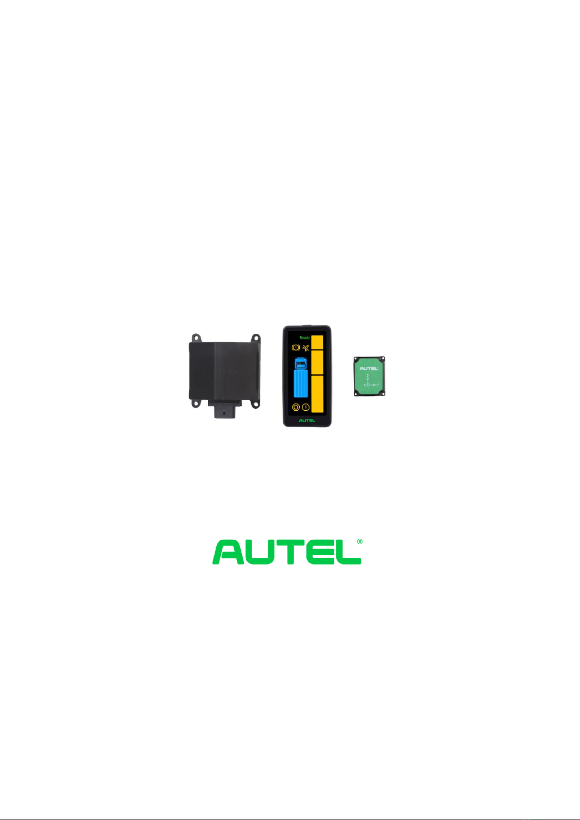
ATS100 is a turn assistant with precise target recognition and vehicle blind spot warn-
ings. The system components are as follows: a millimeter wave radar with an operating
frequency of 76-77 GHz and a maximum RF output power of 12 dBm, a spirit level, a
mounting bracket (optional), a warning screen, a GPS and IMU module, and the cable.
The millimeter wave radar can accurately measure object distance, speed, angle and
other information through the difference in echoes between the transmitting and receiv-
ing electromagnetic waves. It is an all-weather and all-dayturn assistant with a working
temperature of -40℃ - 85℃. The warning screen warns the driver of a dangerous object
in the blind spot and reminds the driver to make timely adjustments on the road to avoid
accidents.
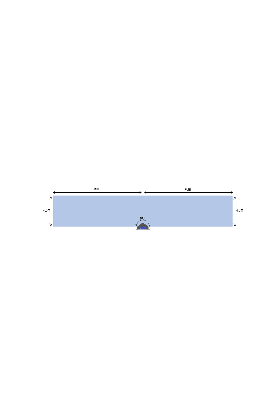
The ATS100 turn assistant covers 180° on one side, no blind spots, with a target detec-
tion range of up to 80 x 4.5m. With a compact structure, it has collision prediction and
graduated alarm function, can be connected with external CAN (Controller Area Net-
work) and CAN FD (Flexible Data) interfaces can be integrated and supports 12 V or
24 V supply voltage.
Figure 1-1ASR100 radar coverage
The warning objects of theATS100 turning assistant include:
Dynamic vulnerable road users moving at speeds equal to or exceeding 5 km/h ,
including pedestrians, bicycles, electric bicycles, etc.
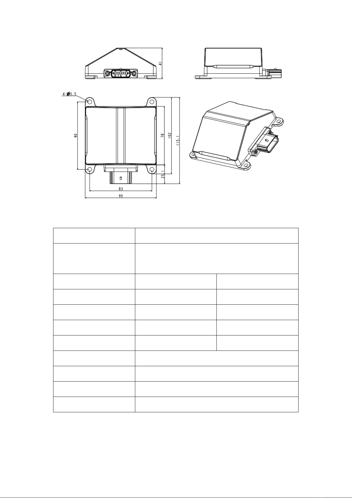
1.1 ASR100 Radar Introduction
The ASR100 77 GHz millimeter wave radar is a compact, rugged radar sensor designed
and manufactured by Autel Intelligence Vehicle® in China to warn heavy duty trucks/
buses etc. of side blind spots with IP69K protection housing, in line with the environ-
ment for commercial vehicle use .